EP0331216B1 - Betriebsverfahren für die Zufuhr von Borsten an eine Bürstenherstellungsmaschine und ein Aufbau für dieses Verfahren - Google Patents
Betriebsverfahren für die Zufuhr von Borsten an eine Bürstenherstellungsmaschine und ein Aufbau für dieses Verfahren Download PDFInfo
- Publication number
- EP0331216B1 EP0331216B1 EP89200053A EP89200053A EP0331216B1 EP 0331216 B1 EP0331216 B1 EP 0331216B1 EP 89200053 A EP89200053 A EP 89200053A EP 89200053 A EP89200053 A EP 89200053A EP 0331216 B1 EP0331216 B1 EP 0331216B1
- Authority
- EP
- European Patent Office
- Prior art keywords
- bundle
- devices
- wrapping
- wreathing
- operating procedure
- Prior art date
- Legal status (The legal status is an assumption and is not a legal conclusion. Google has not performed a legal analysis and makes no representation as to the accuracy of the status listed.)
- Expired
Links
- 238000011017 operating method Methods 0.000 title claims description 21
- 238000004519 manufacturing process Methods 0.000 title claims description 10
- 238000010276 construction Methods 0.000 title claims description 8
- 238000000034 method Methods 0.000 title 1
- 239000000835 fiber Substances 0.000 claims description 28
- 238000005520 cutting process Methods 0.000 claims description 8
- 238000000926 separation method Methods 0.000 claims description 5
- 230000032258 transport Effects 0.000 description 5
- 235000013162 Cocos nucifera Nutrition 0.000 description 1
- 244000060011 Cocos nucifera Species 0.000 description 1
- 230000001788 irregular Effects 0.000 description 1
- 238000012856 packing Methods 0.000 description 1
- 238000005096 rolling process Methods 0.000 description 1
- 239000002699 waste material Substances 0.000 description 1
Images


Classifications
-
- A—HUMAN NECESSITIES
- A46—BRUSHWARE
- A46D—MANUFACTURE OF BRUSHES
- A46D3/00—Preparing, i.e. Manufacturing brush bodies
- A46D3/08—Parts of brush-making machines
- A46D3/082—Magazines for bristles; Feeding bristles to magazines; Knot picking
-
- A—HUMAN NECESSITIES
- A46—BRUSHWARE
- A46D—MANUFACTURE OF BRUSHES
- A46D1/00—Bristles; Selection of materials for bristles
- A46D1/04—Preparing bristles
Definitions
- This invention relates to an operating procedure as well as a construction for the automatic supply of fibres to a brush manufacturing machine.
- This invention especially refers to an operating procedure and construction for the supply of natural fibres, coir in particular, to a machine manufacturing brushes produced from conventionally packed fibres.
- knots formed by the knotted extremities of such strings, ropes or similar are, as known, pushed between the fibres to avoid loosening of the package, during transport among others.
- each fibre bundle is being caught at one extremity after which the tying means which contain the bundle, after the cutting through of the bundle, are pushed off in the longitudinal direction of the fibres.
- this patent application describes means to separate the fibres from each other. These means consist of a moulded channel which is being pushed into the mass of fibres to separate them and along which the fibres drop off.
- the subject of present invention encompasses an operating procedure and a construction for the automatic opening of natural fibre bundles, on the one hand, and the separation into parts of these bundles for the appropriate supply of such to a fibre container, on the other hand, in which way the disadvantages proper to existing systems are systematically being excluded.
- the operating procedure according to the invention mainly consists in catching the wreathing or wrapping means of a fibre bundle ; in separating the fibre bundle in at least two parts ; in cutting the aforementioned wreathing or wrapping means ; in the removal of the wreathing or wrapping means and the subsequent consecutive supply of the separated parts to a fibre container of a brush manufacturing machine.
- Present invention also realtes to a construction which applies aforementioned operating procedure and consists mainly of supporting means for a bundle ; catching means which can be placed behind the wreathing or wrapping of a bundle and retaining such ; means to be inserted into a bundle in order to split it up in at least two parts ; means which catch and retain these separated parts ; and means which cut the wreathing or wrapping loose, after which the catching means remove the wreathing of wrapping at an angle with respect to the longitudinal direction of the bundle and the means to transport the separated parts individually to a fibre container.
- FIG 1 represents schematically the operating procedure according to the invention.
- devices 5 are provided for which intrude between the fibres 6 of the bundle 1 and which then hook up behind the twines 2.
- step bundle 1 is being separated, in this case, in two parts by devices 7.
- the twines 2 are further being cut by means of a knife 8.
- devices 5 are being removed from the bundle 1 which causes the twines 2 to be removed.
- twines 2 are being removed in a direction perpendicular with respect to the fibres 6 in such way that the mixing up of fibres and or pulling of fibres out of the bundle are being avoided while at the same time the fibres are being supplied to the machine in smaller quantities.
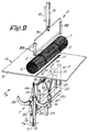
- Figure 2 represents an embodiment which applies aforementioned operating procedure.
- the devices 5 are in this case formed by two hooks, respectively 12, 13 which are for instance each fixed to a bushing 14, 15 which can be slid over a shaft 16 by means of rods 17, 18 which are activated by a pressure cylinder 19 the body of which is being secured by a frame 21.
- the shaft 16 is in this case secured in a frame 21 slidable along guide shafts 22, fixed on aforementioned frame 20, where the frame is being activated by a pressure cylinder 23, the body of which is being secured to frame 20.
- the length of slot 11 is shorter that the length of a bundle 1 but longer than the distance between the twines 2, while the width of the table 10 is also smaller than the length of a bundle so that latter's extremities protrude from the edge of table 10.
- the devices 7 to separate a bundle 1 in two consist in this example of two splitting devices 24, 25 which show a pointed free extremity and which are being placed right next to each other in which the splitting devices 24, 25 can be moved on one hand, in an appropriate manner not shown in the drawings, according to arrows F1 and F2 and, on the other hand, according to arrows F3 and F4.
- Each of the splitting devices 24, 25 is equipped with a hinged jaw, respectively 26, 27, which is being moved by for instance pressure cylinders 28, 29, of which the bodies are secured to the matching splitting devices 24, 25.
- a knife 30 is being represented overhead bundle 1 which is activated for instance by a pressure cylinder 31 which is secured to the frame 20, where this knife can be guided in guide channels 32, 33.
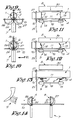
- FIGS 3 through 14 explain further the operating procedure given in accordance with the example in figure 2.
- Bundle 1 consists at this moment of loose fibres 6 which are being separated into parts A and B.
Landscapes
- Engineering & Computer Science (AREA)
- Manufacturing & Machinery (AREA)
- Basic Packing Technique (AREA)
- Treatment Of Fiber Materials (AREA)
- Preliminary Treatment Of Fibers (AREA)
Claims (11)
Applications Claiming Priority (2)
| Application Number | Priority Date | Filing Date | Title |
|---|---|---|---|
| BE8800237A BE1001479A3 (nl) | 1988-03-02 | 1988-03-02 | Werkwijze voor het toevoeren van vezels aan borstelvervaardigingsmachines en inrichting die deze werkwijze toepast. |
| BE8800237 | 1988-03-02 |
Publications (2)
| Publication Number | Publication Date |
|---|---|
| EP0331216A1 EP0331216A1 (de) | 1989-09-06 |
| EP0331216B1 true EP0331216B1 (de) | 1992-02-26 |
Family
ID=3883290
Family Applications (1)
| Application Number | Title | Priority Date | Filing Date |
|---|---|---|---|
| EP89200053A Expired EP0331216B1 (de) | 1988-03-02 | 1989-01-11 | Betriebsverfahren für die Zufuhr von Borsten an eine Bürstenherstellungsmaschine und ein Aufbau für dieses Verfahren |
Country Status (4)
| Country | Link |
|---|---|
| US (1) | US4935640A (de) |
| EP (1) | EP0331216B1 (de) |
| BE (1) | BE1001479A3 (de) |
| DE (1) | DE68900843D1 (de) |
Families Citing this family (8)
| Publication number | Priority date | Publication date | Assignee | Title |
|---|---|---|---|---|
| DE19525808B4 (de) * | 1995-07-15 | 2008-03-20 | Anton Zahoransky Gmbh & Co. | Vorrichtung zum Aufbereiten von Borstenmaterial aus umhüllten Borstensträngen |
| DE10149043C1 (de) * | 2001-10-05 | 2003-03-20 | Rueb F A Holding Gmbh | Verfahren und Vorrichtung zum Herstellen von Bürsten, insbesondere Zahnbürsten |
| DE10356316A1 (de) * | 2003-11-28 | 2005-06-23 | Zahoransky Ag | Einrichtung zum Zuführen von Borstenbunden |
| US10213014B2 (en) * | 2013-07-24 | 2019-02-26 | Zahoransky Ag | Transfer station for transferring bristle filaments |
| US10966527B2 (en) | 2017-06-09 | 2021-04-06 | Steelcase Inc. | Seating arrangement and method of construction |
| US11259637B2 (en) | 2015-04-13 | 2022-03-01 | Steelcase Inc. | Seating arrangement |
| US10021984B2 (en) | 2015-04-13 | 2018-07-17 | Steelcase Inc. | Seating arrangement |
| US10194750B2 (en) | 2015-04-13 | 2019-02-05 | Steelcase Inc. | Seating arrangement |
Family Cites Families (3)
| Publication number | Priority date | Publication date | Assignee | Title |
|---|---|---|---|---|
| DE3411030A1 (de) * | 1984-03-24 | 1985-09-26 | Alfons 8301 Eggmühl Holmer | Ballendrahtschneider |
| BE901006A (nl) * | 1984-11-08 | 1985-05-08 | Boucherie Nv G B | Automatische vulinrichting voor vezelmagazijne en/of kassetten van borstel vervaardigingsmachines. |
| DE3607453A1 (de) * | 1986-03-07 | 1987-09-10 | Zahoransky Anton Fa | Buerstenherstellungsmaschine |
-
1988
- 1988-03-02 BE BE8800237A patent/BE1001479A3/nl not_active IP Right Cessation
-
1989
- 1989-01-11 EP EP89200053A patent/EP0331216B1/de not_active Expired
- 1989-01-11 DE DE8989200053T patent/DE68900843D1/de not_active Expired - Lifetime
- 1989-03-01 US US07/317,592 patent/US4935640A/en not_active Expired - Fee Related
Also Published As
| Publication number | Publication date |
|---|---|
| EP0331216A1 (de) | 1989-09-06 |
| BE1001479A3 (nl) | 1989-11-07 |
| US4935640A (en) | 1990-06-19 |
| DE68900843D1 (de) | 1992-04-02 |
Similar Documents
| Publication | Publication Date | Title |
|---|---|---|
| US4706843A (en) | Dispensing chain of loop lengths of dental floss or the like and method of forming same | |
| EP0331216B1 (de) | Betriebsverfahren für die Zufuhr von Borsten an eine Bürstenherstellungsmaschine und ein Aufbau für dieses Verfahren | |
| US6419283B1 (en) | Automatic knot-tying machine | |
| US4356692A (en) | Method and apparatus for removing an irregularity in a thread | |
| US7257934B2 (en) | Banding machine | |
| CN114852395B (zh) | 绳线打结器以及在绳线中形成两个结的方法 | |
| CN101057012B (zh) | 将由许多平行纱线组成的条带卷绕到绕旋转轴线旋转的滚筒上的方法及装置 | |
| CN112455760B (zh) | 捆绳打结器和用于捆绳打结的方法 | |
| US4561234A (en) | Product tying machine | |
| DE102004056864B3 (de) | Verfahren und Vorrichtung zum Umschnüren einer Ware mit einer Schnur | |
| US4506920A (en) | Knotter for baling machine | |
| US4795201A (en) | Knotting method for baler | |
| DE10111136B4 (de) | Verfahren, Endlos-Rollenware für das Verfahren und Vorrichtung zum Abtrennen von Schlauchabschnitten von einer flachgelegten schlauchförmigen Endlos-Rollenware | |
| RU2779597C1 (ru) | Узловязатель шпагата и способ выполнения двух узлов в шпагате | |
| BE1000367A4 (nl) | Werkwijze voor het toevoeren van vezels aan borstelvervaardigingsmachines en inrichting die deze werkwijze toepast. | |
| JP7224416B2 (ja) | 経糸の整経方法及び部分整経機 | |
| US2603348A (en) | Multiple spool fishing line package | |
| KR102150051B1 (ko) | 원단 포장 장치 | |
| JPS6228823Y2 (de) | ||
| JP3569968B2 (ja) | 花茎結束装置 | |
| US664253A (en) | Knotter for binders. | |
| JPH0379248B2 (de) | ||
| CZ283161B6 (cs) | Zařízení pro ukládání zásoby příze | |
| JP2000053108A (ja) | 糸かけ装置 | |
| JPH04346716A (ja) | 汎用結束機 |
Legal Events
| Date | Code | Title | Description |
|---|---|---|---|
| PUAI | Public reference made under article 153(3) epc to a published international application that has entered the european phase |
Free format text: ORIGINAL CODE: 0009012 |
|
| AK | Designated contracting states |
Kind code of ref document: A1 Designated state(s): DE ES GB IT |
|
| 17P | Request for examination filed |
Effective date: 19890927 |
|
| 17Q | First examination report despatched |
Effective date: 19910529 |
|
| GRAA | (expected) grant |
Free format text: ORIGINAL CODE: 0009210 |
|
| AK | Designated contracting states |
Kind code of ref document: B1 Designated state(s): DE ES GB IT |
|
| PG25 | Lapsed in a contracting state [announced via postgrant information from national office to epo] |
Ref country code: IT Free format text: LAPSE BECAUSE OF FAILURE TO SUBMIT A TRANSLATION OF THE DESCRIPTION OR TO PAY THE FEE WITHIN THE PRE;WARNING: LAPSES OF ITALIAN PATENTS WITH EFFECTIVE DATE BEFORE 2007 MAY HAVE OCCURRED AT ANY TIME BEFORE 2007. THE CORRECT EFFECTIVE DATE MAY BE DIFFERENT FROM THE ONE RECORDED.SCRIBED TIME-LIMIT Effective date: 19920226 Ref country code: ES Free format text: THE PATENT HAS BEEN ANNULLED BY A DECISION OF A NATIONAL AUTHORITY Effective date: 19920226 |
|
| REF | Corresponds to: |
Ref document number: 68900843 Country of ref document: DE Date of ref document: 19920402 |
|
| PLBE | No opposition filed within time limit |
Free format text: ORIGINAL CODE: 0009261 |
|
| STAA | Information on the status of an ep patent application or granted ep patent |
Free format text: STATUS: NO OPPOSITION FILED WITHIN TIME LIMIT |
|
| 26N | No opposition filed | ||
| PGFP | Annual fee paid to national office [announced via postgrant information from national office to epo] |
Ref country code: GB Payment date: 19950110 Year of fee payment: 7 |
|
| PGFP | Annual fee paid to national office [announced via postgrant information from national office to epo] |
Ref country code: DE Payment date: 19950222 Year of fee payment: 7 |
|
| PG25 | Lapsed in a contracting state [announced via postgrant information from national office to epo] |
Ref country code: GB Effective date: 19960111 |
|
| GBPC | Gb: european patent ceased through non-payment of renewal fee |
Effective date: 19960111 |
|
| PG25 | Lapsed in a contracting state [announced via postgrant information from national office to epo] |
Ref country code: DE Effective date: 19961001 |