EP0330455A2 - Dispositif de codage d'images - Google Patents
Dispositif de codage d'images Download PDFInfo
- Publication number
- EP0330455A2 EP0330455A2 EP89301739A EP89301739A EP0330455A2 EP 0330455 A2 EP0330455 A2 EP 0330455A2 EP 89301739 A EP89301739 A EP 89301739A EP 89301739 A EP89301739 A EP 89301739A EP 0330455 A2 EP0330455 A2 EP 0330455A2
- Authority
- EP
- European Patent Office
- Prior art keywords
- data
- image data
- image
- circuit
- background
- Prior art date
- Legal status (The legal status is an assumption and is not a legal conclusion. Google has not performed a legal analysis and makes no representation as to the accuracy of the status listed.)
- Withdrawn
Links
Images


Classifications
-
- H—ELECTRICITY
- H04—ELECTRIC COMMUNICATION TECHNIQUE
- H04N—PICTORIAL COMMUNICATION, e.g. TELEVISION
- H04N19/00—Methods or arrangements for coding, decoding, compressing or decompressing digital video signals
- H04N19/50—Methods or arrangements for coding, decoding, compressing or decompressing digital video signals using predictive coding
- H04N19/503—Methods or arrangements for coding, decoding, compressing or decompressing digital video signals using predictive coding involving temporal prediction
- H04N19/507—Methods or arrangements for coding, decoding, compressing or decompressing digital video signals using predictive coding involving temporal prediction using conditional replenishment
-
- H—ELECTRICITY
- H04—ELECTRIC COMMUNICATION TECHNIQUE
- H04N—PICTORIAL COMMUNICATION, e.g. TELEVISION
- H04N19/00—Methods or arrangements for coding, decoding, compressing or decompressing digital video signals
- H04N19/10—Methods or arrangements for coding, decoding, compressing or decompressing digital video signals using adaptive coding
- H04N19/102—Methods or arrangements for coding, decoding, compressing or decompressing digital video signals using adaptive coding characterised by the element, parameter or selection affected or controlled by the adaptive coding
- H04N19/115—Selection of the code volume for a coding unit prior to coding
-
- H—ELECTRICITY
- H04—ELECTRIC COMMUNICATION TECHNIQUE
- H04N—PICTORIAL COMMUNICATION, e.g. TELEVISION
- H04N19/00—Methods or arrangements for coding, decoding, compressing or decompressing digital video signals
- H04N19/10—Methods or arrangements for coding, decoding, compressing or decompressing digital video signals using adaptive coding
- H04N19/102—Methods or arrangements for coding, decoding, compressing or decompressing digital video signals using adaptive coding characterised by the element, parameter or selection affected or controlled by the adaptive coding
- H04N19/124—Quantisation
- H04N19/126—Details of normalisation or weighting functions, e.g. normalisation matrices or variable uniform quantisers
-
- H—ELECTRICITY
- H04—ELECTRIC COMMUNICATION TECHNIQUE
- H04N—PICTORIAL COMMUNICATION, e.g. TELEVISION
- H04N19/00—Methods or arrangements for coding, decoding, compressing or decompressing digital video signals
- H04N19/10—Methods or arrangements for coding, decoding, compressing or decompressing digital video signals using adaptive coding
- H04N19/102—Methods or arrangements for coding, decoding, compressing or decompressing digital video signals using adaptive coding characterised by the element, parameter or selection affected or controlled by the adaptive coding
- H04N19/132—Sampling, masking or truncation of coding units, e.g. adaptive resampling, frame skipping, frame interpolation or high-frequency transform coefficient masking
-
- H—ELECTRICITY
- H04—ELECTRIC COMMUNICATION TECHNIQUE
- H04N—PICTORIAL COMMUNICATION, e.g. TELEVISION
- H04N19/00—Methods or arrangements for coding, decoding, compressing or decompressing digital video signals
- H04N19/10—Methods or arrangements for coding, decoding, compressing or decompressing digital video signals using adaptive coding
- H04N19/169—Methods or arrangements for coding, decoding, compressing or decompressing digital video signals using adaptive coding characterised by the coding unit, i.e. the structural portion or semantic portion of the video signal being the object or the subject of the adaptive coding
- H04N19/17—Methods or arrangements for coding, decoding, compressing or decompressing digital video signals using adaptive coding characterised by the coding unit, i.e. the structural portion or semantic portion of the video signal being the object or the subject of the adaptive coding the unit being an image region, e.g. an object
-
- H—ELECTRICITY
- H04—ELECTRIC COMMUNICATION TECHNIQUE
- H04N—PICTORIAL COMMUNICATION, e.g. TELEVISION
- H04N19/00—Methods or arrangements for coding, decoding, compressing or decompressing digital video signals
- H04N19/20—Methods or arrangements for coding, decoding, compressing or decompressing digital video signals using video object coding
- H04N19/23—Methods or arrangements for coding, decoding, compressing or decompressing digital video signals using video object coding with coding of regions that are present throughout a whole video segment, e.g. sprites, background or mosaic
-
- H—ELECTRICITY
- H04—ELECTRIC COMMUNICATION TECHNIQUE
- H04N—PICTORIAL COMMUNICATION, e.g. TELEVISION
- H04N19/00—Methods or arrangements for coding, decoding, compressing or decompressing digital video signals
- H04N19/50—Methods or arrangements for coding, decoding, compressing or decompressing digital video signals using predictive coding
- H04N19/503—Methods or arrangements for coding, decoding, compressing or decompressing digital video signals using predictive coding involving temporal prediction
-
- H—ELECTRICITY
- H04—ELECTRIC COMMUNICATION TECHNIQUE
- H04N—PICTORIAL COMMUNICATION, e.g. TELEVISION
- H04N19/00—Methods or arrangements for coding, decoding, compressing or decompressing digital video signals
- H04N19/50—Methods or arrangements for coding, decoding, compressing or decompressing digital video signals using predictive coding
- H04N19/587—Methods or arrangements for coding, decoding, compressing or decompressing digital video signals using predictive coding involving temporal sub-sampling or interpolation, e.g. decimation or subsequent interpolation of pictures in a video sequence
-
- H—ELECTRICITY
- H04—ELECTRIC COMMUNICATION TECHNIQUE
- H04N—PICTORIAL COMMUNICATION, e.g. TELEVISION
- H04N19/00—Methods or arrangements for coding, decoding, compressing or decompressing digital video signals
- H04N19/50—Methods or arrangements for coding, decoding, compressing or decompressing digital video signals using predictive coding
- H04N19/593—Methods or arrangements for coding, decoding, compressing or decompressing digital video signals using predictive coding involving spatial prediction techniques
-
- H—ELECTRICITY
- H04—ELECTRIC COMMUNICATION TECHNIQUE
- H04N—PICTORIAL COMMUNICATION, e.g. TELEVISION
- H04N19/00—Methods or arrangements for coding, decoding, compressing or decompressing digital video signals
- H04N19/60—Methods or arrangements for coding, decoding, compressing or decompressing digital video signals using transform coding
- H04N19/61—Methods or arrangements for coding, decoding, compressing or decompressing digital video signals using transform coding in combination with predictive coding
-
- H—ELECTRICITY
- H04—ELECTRIC COMMUNICATION TECHNIQUE
- H04N—PICTORIAL COMMUNICATION, e.g. TELEVISION
- H04N19/00—Methods or arrangements for coding, decoding, compressing or decompressing digital video signals
- H04N19/10—Methods or arrangements for coding, decoding, compressing or decompressing digital video signals using adaptive coding
- H04N19/102—Methods or arrangements for coding, decoding, compressing or decompressing digital video signals using adaptive coding characterised by the element, parameter or selection affected or controlled by the adaptive coding
- H04N19/103—Selection of coding mode or of prediction mode
- H04N19/107—Selection of coding mode or of prediction mode between spatial and temporal predictive coding, e.g. picture refresh
-
- H—ELECTRICITY
- H04—ELECTRIC COMMUNICATION TECHNIQUE
- H04N—PICTORIAL COMMUNICATION, e.g. TELEVISION
- H04N19/00—Methods or arrangements for coding, decoding, compressing or decompressing digital video signals
- H04N19/10—Methods or arrangements for coding, decoding, compressing or decompressing digital video signals using adaptive coding
- H04N19/102—Methods or arrangements for coding, decoding, compressing or decompressing digital video signals using adaptive coding characterised by the element, parameter or selection affected or controlled by the adaptive coding
- H04N19/124—Quantisation
-
- H—ELECTRICITY
- H04—ELECTRIC COMMUNICATION TECHNIQUE
- H04N—PICTORIAL COMMUNICATION, e.g. TELEVISION
- H04N19/00—Methods or arrangements for coding, decoding, compressing or decompressing digital video signals
- H04N19/10—Methods or arrangements for coding, decoding, compressing or decompressing digital video signals using adaptive coding
- H04N19/134—Methods or arrangements for coding, decoding, compressing or decompressing digital video signals using adaptive coding characterised by the element, parameter or criterion affecting or controlling the adaptive coding
- H04N19/146—Data rate or code amount at the encoder output
- H04N19/152—Data rate or code amount at the encoder output by measuring the fullness of the transmission buffer
-
- H—ELECTRICITY
- H04—ELECTRIC COMMUNICATION TECHNIQUE
- H04N—PICTORIAL COMMUNICATION, e.g. TELEVISION
- H04N19/00—Methods or arrangements for coding, decoding, compressing or decompressing digital video signals
- H04N19/20—Methods or arrangements for coding, decoding, compressing or decompressing digital video signals using video object coding
-
- H—ELECTRICITY
- H04—ELECTRIC COMMUNICATION TECHNIQUE
- H04N—PICTORIAL COMMUNICATION, e.g. TELEVISION
- H04N19/00—Methods or arrangements for coding, decoding, compressing or decompressing digital video signals
- H04N19/30—Methods or arrangements for coding, decoding, compressing or decompressing digital video signals using hierarchical techniques, e.g. scalability
Definitions
- the present invention relates to an image encoding apparatus for encoding a movement image used for a teleconference or video phone.
- a data compression circuit is arranged to compress data in order to transfer a movement image having a very large data amount at a low bit rate.
- the data compression circuit may employ a system of performing different quantization or encoding operations for a still region and a movement region by utilizing the fact that the still portion of an image has a very high inter-frame or inter-field correlation.
- This system is disclosed in, e.g., Japanese Patent Disclosure (Kokai) No. 61-46685.
- input data is divided into a plurality of data blocks by a dividing circuit, and these data blocks are compared with those of an image stored in a frame memory.
- a movement of an image is detected by a motion vector detecting circuit.
- Data blocks of an immediately preceding image are read out from the frame memory, and are input to a variable delay circuit.
- the variable delay circuit selects one data block from the frame memory which corresponds to motion vector data output from the motion vector detecting circuit. Difference between the data blocks output from the variable delay circuit and input data block is calculated.
- a movement region detecting circuit discriminates, based on the differential data and the motion vector data, whether or not the input blocks include a movement region.
- the differential data is quantized by a quantizer, and is input to a selection circuit.
- the selection circuit selects one output of the quantizer in accordance with an output from the motion vector detection circuit.
- the selected quantized output is input to a variable-length encoder and a local decoder.
- the variable-length encoder multiplexes the selected quantized output and the motion vector data from the motion vector detecting circuit and outputs multiplexed data.
- the frame memory is rewritten by the decoded output from the local decoder.
- a movement or transition region is detected based on an inter-frame or inter-field difference, and only the transition region is transferred.
- a region surrounding a face (or eyes or mouth) is limited as a region narrower than the transition region, and bits more than those for regions other than the face region are allocated to the face region.
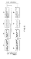
- an image encoding apparatus comprising memory for storing image data corresponding to an object having a specific portion, a specific image extracting circuit for outputting differential data corresponding to a difference between input image data and preceding image data, and extracting specific image data corresponding to the specific portion from the image data on the basis of the differential data, a buffer for matching a generated data amount with an output data amount, an encoding circuit for encoding the differential data and outputting encoded data, a parameter generating circuit for generating a quantization parameter according to at least one of the differential data and a remaining amount of the buffer, a quantizer for quantizing the encoded data output from the encoding circuit in accordance with the quantization parameter so as to allocate more bits to the specific image data than those to the remaining image data, and outputting quantized data, and an output circuit for converting the quantized data to output data and outputting the output data to the buffer.
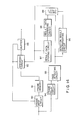
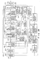
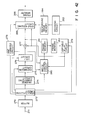
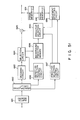
- a frame dropo circuit 11 is arranged to limit image data supplied from, e.g., a TV camera.
- the output terminal of the frame drop circuit 11 is connected to the write terminal of a frame memory 12 for storing image data.
- the readout terminal of the frame memory 12 is connected to a frame memory 14 through a frame delay circuit 13.
- the frame delay circuit 13 delays frame image data read out from the frame memory by a time corresponding to an inter-frame interval, and the frame memory 14 stores the delayed frame image data.
- the readout terminals of the frame memories 12 and 14 are connected to a subtracter 26.
- the output terminal of the subtracter and the readout terminal of the frame memory 12 are connected to a region extracting circuit 15.
- the subtracter 26 calculates a difference between the frame image data stored in the frame memories 12 and 14, and the region extracting circuit 15 extracts a face, eye, or mouth region from the differential data.
- the readout terminal of the frame memory 12 is connected to a dividing circuit 16 for dividing image data stored in the frame memory 12 into a plurality of blocks.
- the output terminal of the dividing circuit 16 is connected, through a subtracter 27, to a movement region selection circuit 17 for discriminating a movement region of an image.
- the output terminal of the movement region selection circuit 17 is connected to an encoding circuit 18 having a plurality of encoders 1 to N.
- the encoding circuit 18 is connected to a multiplexing circuit 20 through a selection circuit 19 for selecting, on the basis of the region extracted by the circuit 15, one output of the encoders 1 to N to which different numbers of bits are allocated.
- the input terminal of the multiplexing circuit 20 is connected to the region extracting circuit 15, the movement region selection circuit 17, and a motion vector detecting circuit 25.
- the multiplexing circuit 20 multiplexes the outputs from these circuits with the output from the encoding circuit 18.
- the output terminal of the multiplexing circuit 20 is connected to a buffer 21 and a local decoder 22.
- the output from the buffer 21 is transferred to an external circuit, and is supplied to the frame drop circuit 11 so as to control a frame drop operation.
- the local decoder 22 is connected to a frame memory 23, and decodes multiplexed data output from the multiplexing circuit 20.
- the decoder 22 writes the decoded data in the frame memory 23.
- the readout terminal of the frame memory 23 is connected to a variable delay circuit 24 and the motion vector detecting circuit 25.
- the motion vector detecting circuit 25 compares the data blocks output from the dividing circuit 16 and the data blocks of the immediately preceding image stored in the frame memory 23 so as to detect a motion vector of an image, and outputs motion vector data.
- the output terminal of the motion vector detecting circuit 25 is connected to the multiplexing circuit 20 and the variable delay circuit 24, and supplies the motion vector data to these circuits.
- the delay amount of the variable delay circuit 24 is changed in accordance with the motion vector data.
- the circuit 24 selects a data block corresponding to the delay amount from the frame memory 23.
- the output terminal of the variable delay circuit 24 is connected to the subtracter 27.
- the region extracting circuit 15 is arranged as shown in Fig. 2.
- Y- and X-axis histogram forming circuits 31 and 35 receive the differential data output from the subtracter 26, and form Y- and X-axis histograms on the basis of the differential data.
- the Y- and X-axis histogram forming circuits 31 and 35 are connected to mean value circuits 32 and 36, respectively.
- the mean value circuits 32 and 36 calculate mean values of the Y- and X-axis histograms, respectively.
- the output terminals of the mean value circuits 32 and 36 are connected to comparators 33 and 37, respectively.
- the comparators 33 and 37 compare the mean values calculated by the mean value circuits 32 and 36 with the histograms output from the histogram forming circuits 31 and 35, respectively.
- the output terminals of the comparators 33 and 37 are connected to transition point detecting circuits 34 and 38 for detecting coordinates of points of transition of the histograms, respectively.
- the output from the transition point detecting circuit 34 corresponding to the Y axis is supplied to the X-axis histogram forming circuit 35 so as to set a forming range of the histogram.
- the frame drop circuit 11 selects frame (or field) image data, and stores the selected data in the frame memory 12.
- the frame image data read out from the frame memory 12 is delayed by the frame delay circuit 13 by a predetermined period of time, e.g., inter-frame interval and the delayed data is stored in the frame memory 14.
- the frame image data input from the frame memory 12 to the dividing circuit 16 is divided into a plurality of data blocks, and each data block is supplied to the motion vector detecting circuit 25.
- the movement detecting circuit 25 compares the data block output from the dividing circuit 16 with the preceding data block read out of the frame memory 23.
- the vector data is input to the variable delay circuit 24, to delay the data block read out of the frame memory 23 by the time corresponding to the vector data.
- the subtracter 27 is supplied with the delayed data block and the input data block output from the dividing circuit 16, to obtain difference data corresponding to the difference therebetween, since the data block delayed according to the vector data is not coincident with the corresponding input data block when the amount of movement exceeds a value determined by the detection accuracy of the movement detecting circuit.
- the difference data is supplied to the movement region selection circuit 17, the data block corresponding to the difference data is selected thereby, and supplied to the encoding circuit 18.
- the encoders 1-N included in the encoding circuit 18 encode the selected data block in accordance with the respective numbers of bits. For example, the encoder 3 encodes the data of an input data block which is constructed by 8 bits to data constructed by 6 bits.
- the subtracter 26 calculates a difference between present frame image data stored in the frame memory 12 and the immediately preceding frame image data stored in the frame memory 14, and outputs data representing the difference (to be referred to as frame-differential data hereinafter) to the region extracting circuit 15.
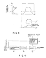
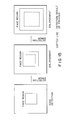
- the region extracting circuit 15 extracts a region including a feature portion such as a face, eyes, mouth, and the like on the basis of the frame-differential data. In this case, as shown in Fig. 3, X- and Y-axis histograms are formed on the basis of an image corresponding to the frame-differential data, and coordinates of points of transition of these histograms are extracted.
- the X-axis histogram When the X-axis histogram is formed, since a large amount of frame-differential data are generated from a region such as a shoulder, as represented by a histogram above a line B - B, a region in the longitudinal direction of an image is limited by points of transition of the Y-axis histogram. In this limited region, the X-axis histogram is formed. Thus, an X-axis histogram above a line A - A can be obtained. A feature region such as a face, eyes, mouth, or the like can be extracted on the basis of the coordinates of the points of transition of the Y- and X-axis histograms.
- the region extracting operation will be described with reference to the region extracting circuit shown in Fig. 2 and the histogram forming circuit shown in Fig. 4.
- Each of the Y- and X-axis histogram forming circuits 31 and 35 is arranged as shown in Fig. 4.
- the Y-axis histogram forming circuit 31 forms the Y-axis histogram.
- 8-bit differential data output from the subtracter 26 is converted to 1-bit data by a thresholding circuit 41.
- the 1-bit data are counted by a counter 42, and the count result is stored in a memory 43.
- the differential data is also supplied to a coordinate address control circuit 44.
- the coordinate address control circuit 44 outputs a coordinate address corresponding to the input differential data to the memory 43. Therefore, the memory 43 stores the count value at the address corresponding to the input differential data. In this manner, the Y-axis histogram shown in Fig. 3 is formed in the memory 43.
- the mean value of the Y-axis histogram read out from the memory 43 is calculated by the mean value circuit 32, thus obtaining a Y-axis mean value.
- the Y-axis mean value is compared with the Y-axis histogram by the comparator 33.
- the transition point detecting circuit 34 detects the coordinates of points of transition of the Y-axis histogram on the basis of the comparison result data.
- the circuit 35 forms the X-axis histogram based on the differential data above the line A - A in the same manner as in the Y-axis histogram forming circuit 31.
- the mean value of the X-axis histogram is calculated by the mean value circuit 36, thus obtaining an X-axis mean value.
- the X-axis mean value is compared with the X-axis histogram by the comparator 37.
- the transition point detecting circuit 38 detects coordinates of points of transition of the X-axis histogram on the basis of the comparison result data.
- the selection circuit 19 selects one encoder corresponding to the coordinate data, and supplies data stored in the selected encoder to the multiplexing circuit 20. More specifically, image data of a region limited by the coordinate data is supplied to the multiplexing circuit 20, and is multiplexed with the motion vector data, the movement region data, and the coordinate data. The multiplexed data is output to an external circuit through the buffer 21, and updates the frame memory 23 through the local decoder 22.
- an image of one person is encoded.
- the present invention can also be applied to a case wherein images of a plurality of persons are encoded, as shown in Fig. 5.
- coordinate data corresponding to a face output from the region extracting circuit 15 is input to a control circuit 45, and frame image data read out from the frame memory 12 is input to and stored in a frame memory 46.
- the control circuit 45 limits a processing range of the frame image data stored in the frame memory 46 in accordance with the input coordinate data.
- the limited image data in the frame memory 46 is input to an edge detecting circuit 47, and an edge of the limited image data is detected.
- the edge data is converted to binary data by a converting circuit 48, and is rewritten in the frame memory 46.
- a labeling circuit 49 selects 8-conectivity data from the image data stored in the frame memory 46, and combines and labels these image data.
- a coordinate detecting circuit 50 detects coordinates of each vertex of a rectangle including a region provided with the same label, and outputs its coordinate data.
- the coordinate data is input to the selection circuit 19, so that image data corresponding to a part of a face, e.g., eyes, a mouth, or the like can be extracted.
- the movement region is detected based on the frame-differential data, an important feature portion, i.e., a face, eyes, or mouth is detected from the movement region, and a larger number of bits are allocated to the feature portion.
- image data can be encoded so that a natural image which is easy to see can be reproduced.
- Frame image data read out from a frame memory 51 is delayed by a predetermined period of time corresponding to a one-frame period by a frame delay circuit 63, and the delayed data is stored in a frame memory 64. More specifically, the frame memory 64 stores a frame image signal of the immediately preceding frame.
- the frame image data stored in the frame memories 51 and 64 are input to a face detecting circuit 65, and difference data therebetween is calculated.
- the differential data is input to a step size-determining circuit 66.
- a subtracter 52 calculates a difference between a data block read out from the frame memory 51 and a data block selected from a frame memory 57 by a variable delay circuit 59, and outputs differential data.
- the variable delay circuit 59 selects the data block from the frame memory 57 in correspondence with the motion vector data from a motion vector detecting circuit 60.
- the differential data is subjected to DCT (Discrete Cosine Transform) processing by a DCT circuit 53, and the DCT data is supplied to a quantizing circuit 54.
- the quantizing circuit 54 quantizes the DCT data in accordance with an output signal from the step size-determining circuit 66 (to be described later).
- the quantized data is input to a multiplexing circuit 67, and is multiplexed with the motion vector data output from the motion vector detecting circuit 60 and the face detection data output from the face detecting circuit 65.
- the multiplexed data is output to an external circuit through a buffer 62.
- the quantized data output from the quantizing circuit 54 is subjected to inverse DCT processing by an inverse DCT circuit 55, and the inverse DCT data is input to an adder 56.
- the adder 56 adds the inverse DCT data to a data block read out from a block memory 58.
- the output data from the adder 56 is written in the frame memory 57 as locally encoded data.
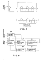
- the step size-determining circuit 66 determines a quantizing step size on the basis of buffer amount data from the buffer 62 and face detection data output from the face detecting circuit 65, and outputs the step size data to the quantizing circuit 54.
- a buffer amount-to-step size converter 71 determines the step size on the basis of a predetermining corresponding relationship between the buffer amount and the step size.
- the step size data thus determined is input to a x1 (one multiplying) circuit 72 which multiplies the step size data with 1, to unchange the size of the step size data, and a xa (a multiplying) circuit 73 which multiplies the size of the step size data with a (a > 1).
- the outputs from these circuits 72 and 73 are switched by a switch 74.
- the face detection result is 1 (face region)
- the output from the x1 circuit is selected.
- the face detection result is 0 (region other than face)
- the output from the xa circuit 73 is selected. That is, in a region other than the face, a parameter is changed to degrade image quality.
- a data amount to be generated is decreased, and a buffer amount of the buffer 62 is decreased accordingly.
- a larger number of bits can be essentially allocated to the face region by data fed back from the buffer 62 in the next encoding step.
- the quantizing circuit 54 quantizes the DCT data on the basis of a new quantizing step size to decrease a data amount.
- a face detection method performed by the face detecting circuit 65 will be described below.
- Fig. 9 shows frame-difference image data formed by the face detecting circuit 65.
- the image data is binarized to data "1" or "0" by a predetermined first threshold value.
- the number of pixels corresponding to a value larger than the first threshold value, i.e., 1 is counted in each of the horizontal and vertical directions, thus forming Y- and X-axis histograms.
- a face region is detected based on the histograms.
- the top of a head is detected first.
- the top of the head can be obtained by detecting a point Ys which is detected by detecting transition points of the Y-axis histogram and exceeds a predetermined second threshold value.
- the left and right ends of the head portion are then detected.
- the width A can be calculated by the following equation: ⁇ ⁇ (Y - Ys) x 0 for p - 1/4 or 1/5
- the lower end of the face region is then detected.
- the lower end of the face region is difficult to obtain based on the histogram.
- a predetermined ratio y is multiplied with the head portion width to calculate a head portion length.
- the value y is preferably 1.3 to 1.6.
- the face region is designated by a rectangle defined by coordinates Xs, Xe, Ys, and Ye.
- a larger number of bits can be distributed to a face region inside the rectangle.
- Fig. 11 shows another method of detecting a face region.
- the coordinates Xs, Xe, Ys, and Ye are calculated in units of pixels.
- the face region is detected in units of blocks.
- frame-difference image data is divided into a plurality of blocks each having a predetermined size.
- the size of the block can be either equal to or smaller than that of an encoding block.
- the number of pixels exceeding the predetermined first threshold value in the block is counted.
- the count value of each block is sequentially compared with a second threshold value from the upper end portion of a frame, and a block exceeding the second threshold value first is detected as a block including the top of a head.
- the Y coordinate Ys of the top of the head is determined by this block.
- the count value of the block is compared with the second threshold value in the range of the width A from the top of the head represented by the coordinate Ys.
- the coordinate of a block having the leftmost coordinate is determined as the left-end coordinate Xs of the face region
- the coordinate of a block having the right-most coordinate is determined as the right-end coordinate Xe.
- the lower-end coordinate Ye of the face region is determined in the same manner as in the method shown in Fig. 9.
- the face region data obtained by the method shown in Fig. 9 or 11 must be sent to a reception side as additional data.
- data to be supplied basically are only three data Xs, Xe, and Ys, even if 8 bits are used per point, 24-bit additional data can be supplied per frame.
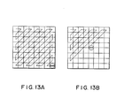
- a conversion coefficient region (8 x 8 blocks) obtained by a DCT shown in Figs. 13A and 13B is sent out while its scan direction is changed from raster-scanning to zigzag scanning by a scanning type converting circuit 81.
- zigzag scanning a higher frequency component is scanned later.
- Data converted to a binary value "0" by quantization before the scanning type conversion tends to be easily generated in a higher frequency region. Therefore, upon sending of data, coefficients are monitored in the scan order, and a code EOB (End Of Block) is added after the last non-0 coefficient. Thus, a series of the following 0 coefficients are replaced with the codes EOB.
- the code EOB is inserted after the normal sending operation, i.e., the last non-0 coefficient (Fig. 13A).
- the code EOB is forcibly inserted at a fixed position, and the following coefficients are omitted (Fig. 13B).
- the number of coefficients of the region other than the face is decreased, and the number of bits to be allocated can be decreased.
- address data indicating a face region may be transmitted, and a quantizing step size may be changed in accordance with the inside/outside of the face region.
- an identification code indicating whether or not a bit distribution is changed may be transmitted.
- the identification code may transferred through a transmission line different from that for the movement image signal.
- frame image data is stored in a frame memory 91 through a frame drop circuit 90.
- the frame drop circuit 90 drop input frame image data when a buffer amount of a buffer 93 exceeds a predetermined threshold value.
- the input frame image data is delayed by a predetermined period of time corresponding to one frame by a frame delay circuit 94.
- a face detecting circuit 95 detects a face region on the basis of a difference between two frame image data, and outputs face region data.
- the face region data is constituted by map data representing a face region as "1" and representing a region other than the face region as "0" or coordinate data of a face region surrounded by a rectangle or circle.
- the face region data output from the face detecting circuit 95 is input to a detection result discriminating circuit 96 for discriminating validity of the data.
- the area of the face region is calculated on the basis of the face region data, i.e., the map data or coordinate data. The calculated area is compared with a predetermined threshold value. When the area is smaller than the threshold value, it is determined that the face region data is not valid. If the face region is represented by a rectangle, the length and width of the rectangular face region are compared with corresponding threshold values. If one of the length and width is smaller than the corresponding threshold value, it is determined that the face region data output from the face detecting circuit 95 is not valid.
- the previously detected face region data is compared with the present face region data, and if the comparison result is largely changed with respect to an area or position, it is determined that the present face region data is not valid.
- a switching circuit 99 is controlled in accordance with the determination result from the discriminating circuit 96. If it is determined that the face region data is valid, the immediately preceding face region data output from a result data storing circuit 97 and a result data expanding circuit 98 or face region data obtained by correcting the immediately preceding face region data is supplied to an encoding circuit 92 and the result data storing circuit 97 as new face region data.
- the face region data is used for changing the numbers of bits to be allocated to the face region and a region other than the face in the encoding circuit 92.
- the face region data is stored in the result data storing circuit 97 as backup data when face region data obtained in the next face region detection is not valid.
- the result data expanding circuit 98 expands the face region data stored in the result data storing circuit 97 according to a predetermined rule (e.g., by ten pixels in each of the four directions).
- a predetermined rule e.g., by ten pixels in each of the four directions.
- control method of the frame drop circuit 90 and the encoding circuit 92 using data which is output from the buffer 93 and represents a buffer amount, and the face region detection method of the face detecting circuit 95 are the same as those in the above embodiment.
- Fig. 16 shows an embodiment wherein an amount of encoded data included in a human face region is discriminated from that in the other region.
- frame image data is stored in a frame memory 102 through an input terminal 101.
- the stored frame image data is read out from the memory 102 while being divided into a plurality of blocks under the control of a controller 106, and is encoded to a plurality of encoding blocks, as shown in Fig. 17.
- each block size is set to be 2 x 2, and pixels of a block to be presently encoded are given by Xo to X 3 .
- the lower right pixel Xo in the block is predicted on the basis of already encoded pixels (e.g., C in a block 7, D and E in a block 8, and A and B in a block 12).
- a predictor X can be calculated by the following equation:
- the values A, B, C, D, and E are stored in a memory 108, and a predictor circuit 107 calculates equation (1). If
- the predictor Xo and the quantized value are added by an adder 105, and a local decoded signal Xo can be obtained as follows:
- the local decoded signal X ⁇ 0 is stored in the memory 108.
- X 0 - X ⁇ 0 I is smaller than the predetermined threshold value THo, the data (Xo -Xo) is neither quantized nor encoded.
- the predictor X ⁇ o having the relationship given by the following equation is stored in the memory 108:
- predictors X 1 , X 2 , and x 3 are calculated by the following equations:
- X i - X i than TH i is neither quantized nor encoded, and a predictor X ⁇ o having the relationship given by the following equation is used as the local decoded signal Xo:
- the significant block is determined based on whether or not Xo is decoded. If Xo is not encoded, X 1 to X 3 are not encoded.
- Fig. 18 shows the quantizing circuit.
- data (X i - X to be quantized is input to an absolute value circuit 122 and a sign circuit 128 through an input terminal 121.
- the absolute value circuit 122 converts the data (Xi - X;) into an absolute value
- the other input terminal of the subtracter 123 receives one of threshold values THo to TH 3 preset for each pixel through the input terminal 121.
- the subtracter 123 outputs a signal H; given by the following equation:
- the determination circuit 124 determines the sign of the signal Hi. If it is determined that the sign of the signal is negative, a switch 125 is released, and the signal Hi is not quantized. If it is determined that the sign is positive, the switch 125 is closed, and the signal Hi is supplied to a quantizing circuit 126 to be quantized.
- the quantizing circuit 126 may have either nonlinear quantizing characteristics (Fig. 19) or linear quantizing characteristics.
- the quantized signal output from the quantizing circuit 126 is input to an adder 127, and is added to the threshold value THi input to the adder 127 through the terminal 121.
- the sum signal is supplied to the sign circuit 128, and is encoded in association with the input signal (Xi - Xi).
- the encoding circuit 128 outputs the encoded quantized signal Q(X i - X i ) to an external circuit, e.g., a decoder through an output terminal 129.
- the decoder must know the threshold values THo to TH 3 in order to decode the signal Q(X i - Xi). Therefore, the threshold values THo to TH 3 are also encoded and supplied. If a threshold value is fixed regardless of an input image, data corresponding to input/output characteristics (Fig. 20) of the quantizing circuit 126 can be written in a ROM, and can be constituted by a single ROM.
- a block size is 2 x 2.
- a block is constituted by 8 x 8 pixels.
- a predictor error of a lower right pixel (indicated by hatching) of 8 x 8 pixels is encoded.
- Fig. 21 B predictor errors of lower right pixels in 4 x 4 pixels other than a block including the previously supplied pixel (indicated by a black dot) are compared with a threshold value TH 1 , and the predictor errors exceeding a threshold value TH 2 are encoded.
- predictor errors of pixels other than the previously supplied pixels (indicated by black dots) and exceeding a threshold value TH 3 are encoded, as shown in Fig. 21 C.
- the processing described above is performed separately for inter-frame prediction and intra-frame prediction, and significant pixels exceeding threshold values are supplied.
- a corresponding motion-vector-detected pixel in the immediately preceding frame is used as a predictor, while in the intra-frame prediction, the predictor of the pattern shown in Fig. 21A can be calculated by the following equations:
- the predictors of the patterns shown in Figs. 21 C and 21 D can be obtained by the above equations.
- a significant pixel pattern formed based on the predictors obtained as described above can be compressed by three pixels for each of patterns shown in Figs. 21A to 21D, i.e., variable-length encoded and can be transmitted.
- Xo can be calculated in the same manner as in the above embodiment.
- a method of calculating Xi and X 4 is different from the above embodiment, and X 1 and X 4 are calculated as follows:
- X 2 and X 8 can also be calculated by the above equations.
- An image signal input through an input terminal 131 is stored in a memory 132 in units of frames or blocks. Each block is constituted by 8 x pixels.
- the circuit 133 detects a significant block from the input block.
- a difference between the present block and the immediately preceding corresponding block is calculated, and an accumulated sum of the squared values of differences is compared to a predetermined threshold value TH B . If the accumulated sum is larger than THe, the corresponding block is determined as a significant block. If the input block is not a significant block, a frame memory 142 is not rewritten.
- a movement vector indicating a parallel movement amount of an image is detected by a motion vector detecting circuit 134.
- the address is shifted by a value corresponding to the motion vector, and the memory 142 is addressed by the updated addresses, thus obtaining a motion-vector-compensated inter-frame predictor signal Xv.
- the block is divided into 2 x 2 subblocks, as shown in Fig. 17, and image signal processing is performed for each subblock. If the pixels of the present subblock are represented by Xo to Xs, the intra-frame predictor Xlo of the lower right pixel Xo can be calculated as follows:
- the inter-frame predictor XvO is a corresponding motion-vector-compensated pixel value in the immediately preceding frame.
- a predictor selector 138 determines which one of XI and Xv is selected. In this determination, if the absolute value of a difference between a pixel A or B closest to Xo and a corresponding pixel of a preceding frame is larger than a predetermined threshold value TH s , the inter-frame predictor is selected by a switch 136; otherwise, the intra-frame predictor is selected by the switch 136.
- a difference between Xo and the selected predictor P 0 is calculated by a subtracter 135, and is quantized by a quantizing circuit 137.
- the quantizing circuit 137 is arranged as shown in Fig. 18. Only when the absolute value of the difference is larger than a threshold value, the difference is quantized. Note that the threshold value can be changed according to a stored amount of a buffer 144. If the output from the quantizing circuit 137 is Q(Xo - X Po), a local decoded signal is obtained as follows:
- 3 of the pixels Xi to X 3 are obtained by equations (4) to (6), and inter-frame predictors Xvi to X ⁇ vs are read out from the frame memory 142.
- the predictor selector 138 determines based on a pixel closest to the already encoded pixel which one of the intra- and inter-frame predictors is selected. For X 1 to X 3 , since the intre-frame predictors have considerably smaller predictor errors, the intra-frame predictors can always be selected.
- of a difference between the selected predictors Xp; and X ⁇ i is compared with a threshold value TH i .
- Significant block data, significant subblock data, significant pixel data, and the like are also encoded by the run-length encoding method, Huffman encoding method, or the like.
- the threshold values THo to TH 4 are changed in accordance with a buffer amount in units of frames, and are encoded at the beginning of a frame. If the threshold values TH o to TH 4 are fixed, they need not be encoded.
- the buffer 144 has a function of smoothing a speed of encoded data and outputting the encoded data.
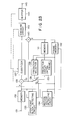
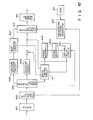
- an image signal input to an input terminal 201 is stored in a frame memory 202 frame by frame.
- the image signal read out from the memory 202 is supplied to a movement region data encoding circuit 203.
- an image signal corresponding to a movement region is encoded.
- the input image is divided into a plurality of image data blocks by a dividing circuit 204.
- the blocks are supplied to a significant block determining circuit 205 and a differential circuit (or subtracter) 206.
- the significant block detecting circuit 205 determines whether or not an input image data block is significant.
- the differential circuit 206 calculates a difference between the input image data block and a data block stored in a frame memory 211 and corresponding to the input data block. If the difference is small and when a map forming circuit 223 (to be described later) determines that the entire block corresponds to a background, the significant block detecting circuit 205 determines the input data block as an insignificant block, and does not send the input data block to the next stage. Otherwise, the input data block is determined as a significant block, Thus, a block address of the input data block is supplied to a multiplexing circuit 228, and image data in the data block is supplied to a differential circuit 207 and a motion vector detecting circuit 208.
- Image data stored in the frame memory 201 is also supplied to the map forming circuit 223 and a background image processing section (or background memory) 224.
- the background image processing section 224 calculates a difference between images of two adjacent frames of input images, e.g., a frame difference between two successive frames, and detects a contour of a movement region in the difference image.
- the section 224 determines input image data outside the contour as a background image, and stores it as background image data.
- the map forming circuit 223 compares the background image data stored in the background image processing section 224 with image data of a new input frame so as to separate the image data of the new input frame into a background region and a movement region and to form a map indicating a boundary (contour of the movement region) therebetween.
- the formed map is used for encoding on the transmission side in the significant block detecting circuit 205, the motion vector detecting circuit 208, a conditional pixel replenishment determining circuit 213, a background change circuit 214, and is encoded by an contour encoding circuit 227 to determine whether reception data (movement region data) is output or the content of the background image processing section 224 is output upon decoding on the reception side.
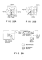
- a variable-length chain encoding method shown in Fig. 25 can be used as an example of an encoding method of contour data in the outline encoding circuit 227.
- a variable-length chain encoding method shown in Fig. 25 can be used. In this method, two bits are allocated to each image in a total of three directions (indicated by solid arrows in Fig. 25) and four bits are allocated to each in other directions (indicated by broken arrows in Fig. 25) to have a moving direction (indicated by a bold arrow in Fig. 25) from a preceding pixel as the center.
- a sample dot string of an contour is represented by relative coordinates to be encoded, and on the reception side, points between the adjacent decoded sample dot strings are spline-interpolated.
- the motion vector detecting circuit 208 receives image data of a block which is determined as a significant block by the significant block detecting circuit 205 and map data which is output from the map forming circuit 223 as boundary data between the background and movement regions, and retrieves the content of the frame memory 211 storing the input image of the immediately preceding frame so as to detect an optimal motion vector. In this case. in an input block and a retrieved block, pixel values of pixels corresponding to the background portion of the input block are cleared to zero, errors are evaluated, and matching is then performed (see Fig. 26). Thus, the motion vector detected by the motion vector detecting circuit 208 can be prevented from being influenced by a background.
- the movement vector detected by the motion vector detecting circuit 208 is supplied to the multiplexing circuit 228 and is also input to a variable delay circuit 209.
- the variable delay circuit 209 supplies image data of a block having an offset corresponding to the motion vector to the differential circuit 207 and a block memory 210.
- a predictor error between the input block and a motion-vector detected predictor block is calculated.
- an error at a position corresponding to a movement region of the input block is evaluated by the conditional pixel replenishment determining circuit 213.
- conditional pixel replenishment determining circuit 213 determines to replenish conditional pixels for the block, and supplies a determination signal to the multiplexing circuit 228 and the block memory 210. In addition, the circuit 213 stops supply of the predictor error to the next stage (background change circuit 214). Upon reception of the determination signal, the block memory 210 transfers the stored image data, i.e, image data selected by the variable delay circuit 209 to the frame memory 212.
- the conditional pixel replenishment determining circuit 213 determines that an error at a position corresponding to the movement region of the input block of the predictor error calculated by the differential circuit 207 is large
- the predictor error is input the background change circuit 214.
- the background change circuit 214 replaces pixels at positions corresponding to the background of the input block with a calculated predetermined value.
- a luminance of the most contour of the movement region, or an average luminance of pixels in the movement region can be used.
- Figs. 27(a) and 27(b) show a case wherein background pixels are changed with the most contour luminance.
- Fig. 27(a) shows a state before the pixels are changed and
- Fig. 27(b) shows a state after the pixels are changed.
- Image data of a block in which luminance values of the background portion are changed is cosine-converted by a DCT circuit 216, and a conversion surface is divided into a plurality of regions.
- a significant region detecting circuit 217 determines based on a threshold value whether or not these regions are significant regions.
- the significant region detecting circuit 217 supplies an address of a region determined as a significant movement region to the multiplexing circuit 228, and image data of the significant movement region is input to a normalizer/ quantizer circuit 218 to be normalized and quantized.
- the normalizer/quantizer circuit 218 supplies a normalization coefficient and quantized data to the multiplexing circuit 228 and an expansion circuit 220.
- the quantized data is locally decoded by a local decoder including a inverse quantizing circuit 219, an expansion circuit 220, an IDC circuit 221, and an adder 222, and is stored in a frame memory 212.
- the image data stored in the frame memory 212 is transferred to the frame memory 211 at a frame timing, and is evaluated by the motion vector detecting circuit 208 and the significant block detecting circuit 205.
- Background image data stored in the background memory 224 is input to a background transmission control circuit 225.
- the background transmission control circuit 225 always monitors the amount of a content of a buffer 229 connected to the output of the multiplexing circuit 228. When the amount of the content of the buffer 229 is decreased, the control circuit 225 causes the background memory 224 to supply many image data to a background encoding circuit 226.
- the background transmission control circuit 225 also monitors addresses of already transmitted pixels in the background memory 224. Data read out from the background memory 224 is encoded by the background encoding circuit 226.
- the background encoding circuit 226 generates a header in synchronism with a frame, and the encoding result (background data) of background image data is supplied to the multiplexing circuit 228.
- the header includes a frame header, and data (background header) obtained by variable-length encoding data associated with the number of bits of the subsequent background data.
- background header data obtained by variable-length encoding data associated with the number of bits of the subsequent background data.
- the background data and the movement region data are distinguished from each other.
- DPCM in units of pixels
- transform coding in units of blocks, or vector quantization
- the background data (frame header, background header, and background data) obtained from the background encoding circuit 226 is time-divisionally multiplexed with contour data (contour header and contour data) from the contour encoding circuit 227, movement region data (significant address from the significant block detecting circuit 205, conditional pixel replenishment data from the conditional pixel replenishment determining circuit 213, significant movement region data from the significant region determining circuit 217, the normalization coefficient and quantized data from the normalizer/quantizer circuit 218.
- contour data contour data
- movement region data significant address from the significant block detecting circuit 205
- conditional pixel replenishment data from the conditional pixel replenishment determining circuit 213
- significant movement region data from the significant region determining circuit 217 the normalization coefficient and quantized data from the normalizer/quantizer circuit 218.
- the multiplexed data having a frame arrangement shown in Fig. 28 is transmitted to the reception side through the buffer 229.
- the number of updated pixels of the entire frame is counted after scene change, and when the ratio of the updated pixels exceeds a predetermined value, the entire data is transmitted.
- the background memory 224 is divided into a plurality of blocks, and when all the pixels in a block are updated at least once after scene change, data is transmitted together with a block address.
- the size of block and an encoding method may be or may not be the same as those used when movement region data is transmitted.
- a control device is necessary for performing the following operations: managing an updating condition of the background memory 224 after scene change using a map, and for, when pixels the number of which exceeds a predetermined ratio of the frame are simultaneously changed, determining a scene change, and clearing of the map indicating the updating condition in response to the determination of the scene change.
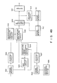
- Fig. 29 shows an embodiment using the method (3).
- the arrangement shown in Fig. 29 is substantially the same as that in the embodiment shown in Fig. 24, except that an update map checking circuit 230 is added.
- the updating condition is observed in units of blocks, and when all the pixels in a block are updated, a corresponding block address is output to the background transmission control circuit 225 and the background encoding circuit 226.
- the background encoding circuit 226 encodes the background data of a block corresponding to the input block address in units of blocks, and outputs the encoded data to the buffer 229.
- a background buffer (not shown) is connected to the output of the background encoding circuit 226, and background data can be transmitted in accordance with the content of the buffer 229, as in the embodiment shown in Fig. 24.
- a predetermined amount of background data can be transmitted in synchronism with a frame like in the method (1), or a predetermined amount of background data can be transmitted regardless of the frame like in the method (2).
- the content of the background memory is formed by data of those sent as movement region data.
- the significant block detecting circuit 205 receives the frame difference image, a difference image between the input image data from a differential circuit 232 and background image data stored in the background memory 224, and data indicating an updating condition of the background memory on the reception side and supplied from an update map checking circuit 231.
- a transmission mode is controlled by the following rules:
- the significant block detecting circuit 5 outputs data for selecting 2 bits per block in accordance with the conditions I) to IV). Only when the condition II) is selected, the significant block detecting circuit 205 outputs an update signal to the update map checking circuit 231, stops the operation of the motion vector detecting circuit 208, and outputs a signal for fixing the motion vector to 0.
- a small threshold value is preferably used.
- Fig. 31 shows the arrangement of the background image processing section 224 shown in Fig. 24 in detail.
- a frame drop circuit 241 performs control for supplying input images of two adjacent frames to frame memories 242 and 243 in order to obtain a difference image between the two adjacent frames, and frame-drop control using a processing end signal from an update control circuit 249 in order to form an appropriate interval between the two frames.
- a frame difference image of the input images of the two frames in the frame memories 242 and 243 is converted to absolute-value image data by an absolute value circuit 245, and the image data is stored in a frame memory 246.
- the absolute-value image data in the frame memory 246 is input to a contour detecting circuit 247.
- the contour detecting circuit 247 detects a rough contour enclosing a true contour by using the absolute value.
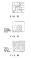
- a map forming circuit 248 forms a map indicating an update position shown in Fig. 32 on the basis of the output from the contour detecting circuit 247.
- the update control circuit 249 updates the content of a background image memory 250 with the content of the frame memory 242 with reference to this map or stores the content of the background image memory 250.
- a delay circuit 251 delays the output from the frame memory 243 by a time corresponding to a processing time of a differential circuit 244, the absolute value circuit 245, the frame memory 246, the contour detecting circuit 247, the map forming circuit 248, and update control circuit 249.
- the delayed frame image data is written in the background frame memory in units of pixels only when updating is permitted by a signal from the update control circuit 249.
- Fig. 33 shows an outline of a movement region (in this case, a person) obtained based on a frame difference image. Since a portion inside the contour includes the movement region of the presently input frame (indicated by hatching) and a new background portion upon comparison with the previously input frame, a concealed background cannot be updated by a single updating operation. However, when a person moves, a portion which cannot be updated in a first updating operation may be updated in a second or subsequent updating operation. As shown in Fig. 34, a portion newly included in a portion outside the contour of the frame difference image is updated, so that only a background can be stored in the background memory 224.
- Fig. 35 images of two adjacent frames along the time base must be employed so as to reduce an area of a background region inside the outline.
- an interval between the two frames can be arbitrarily set in accordance with an updating interval and a processing time.
- frames between t1 + ⁇ 1 and t2, t1 and t1 + ⁇ 1, and t2 and t2+A2 are dropped by the frame drop circuit 241.
- ⁇ 1 and A2 can be frame intervals.
- a frame difference image 1 is obtained by a difference between the frames t1 and t1 + ⁇ 1
- a frame difference image 2 is obtained by a difference between the frames t2 and t2+A2.
- FIG. 35 Portions outside the contours are updated as shown in Fig. 35.
- Fig. 34 a portion of hatched lines inclined upward to the right is updated during a time interval (t1, t1+ ⁇ 1), and a portion of hatched lines inclined downward to the right is updated during a time interval (t2, t2+A2).
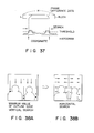
- Fig. 36 shows an arrangement of the contour detecting circuit 247 shown in Fig. 30.
- a histogram forming circuit 262 forms a histogram in the short-side direction of the strip.
- An edge detecting circuit 263 searches the histogram from the two edges of the strip while comparing it with a given threshold value. The circuit 263 outputs coordinates of points where searched values exceed the threshold value as contact points of an outline for the first time.
- Fig. 38 shows an improved operation principle of contour detection method.
- a contour edge is searched in the vertical direction, and edge positions of outlines in strips at both the edges of a frame, and a position of a strip in which an edge position has a minimum value are obtained.
- horizontal search starts from a portion above the detected contour edges at both the edges of a frame and from a portion above the detected contour edge at a position where the strip having a minimum value is present.
- contour detection can be performed even when there are two persons or when a movement region starts from the edge of the frame.
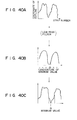
- a method of searching the minimum value will be explained below. Assume that a contour position shown in Fig. 39 is obtained. When a strip having a minimum value is searched from this coordinate series, a very local minimum value point may often be obtained, as indicated by an arrow in Fig. 39. In order to exclude such a minimum value point and to select a significant minimum value point, the coordinate series data is sampled through a low-pass filter, so that a minimum value point is roughly searched. The original series data is searched in detail around the found minimum value position. Such a hierarchical search can be performed.
- Fig. 40A shows a profile of contour position coordinates.
- the coordinate series data is passed through a low-pass filter so as to obtain a profile from which local changes are removed, as shown in Fig. 40B.
- This profile is subsampled to search candidates of a minimum value at positions indicated by marks "0".
- a mark "@ " indicates a candidate of a found minimum value.
- a zone surrounded by dotted lines in profile of Fig. 40C, surrounding the candidate of the minimum value, and obtained in profile (Fig. 40B) is searched, and a minimum value obtained from the zone is employed as a true minimum va!ue. In this manner, the minimum value can be searched.
- the map forming circuit 223 receives the input image data from the frame memory 202 and image data read out from the background memory 224. When a difference image between these data is obtained and its contour is detected, a region including an contour of an actual movement region may often be obtained. Thus, an imaginary band of a constant width is formed inside the outline, and pixel data in a portion inside the band is multiplied with an edge detection operator (e.g., Sobel operator). Pixels having large products are searched in the widthwise direction of the band, thus forming a new contour.
- an edge detection operator e.g., Sobel operator
- Fig. 42 is a block diagram showing a reception-side arrangement corresponding to the transmission-side arrangement shown in Fig. 24.
- the quantized data is inverse-quantized by an inverse quantizing circuit 274, and is denormalized by a denormalizer 275 with reference to the normalization coefficient.
- the denormalized data is arranged in units of regions, and is subjected to inverse cosine transform by an IDCT circuit 276.
- the transformed data is output to an adder 277.
- the motion vector is input to a variable delay circuit 279, and a block corresponding to the motion vector is selected from a frame memory 282.
- the selected block is input to the adder 277.
- the output from the adder 277 is written at a position corresponding to the block address in a frame memory 281 by a write control circuit 280.
- the output from the variable delay circuit 279 is directly written in the frame memory 281 by the write control circuit 280.
- the content of the frame memory 281 is transferred to the frame memory 282 in synchronism with a frame.
- the background data separated in the demultiplexing circuit 273 is decoded by a decoding circuit 283, and the decoded data is written in a background image memory 284.
- the contour data is decoded by a map forming circuit 278 to be converted to a map.
- the movement region image data from the adder 277 and the variable delay circuit 279 and the background image data from the background image memory 284 are synthesized by a synthesizing circuit 285 in accordance with the map from the map forming circuit 278, and the synthesized data is stored in a frame memory 286. Thereafter, the synthesized data is output to a monitor (not shown) and is displayed thereon. In this case, for a background, the content of the background image memory 284 is successively displayed unless a scene change occurs. Thus, an image which is free from flickering and is easy to see can be obtained.
- a contour of a movement region in a difference image between images of two adjacent frames of input images is detected, and input image data outside the outline of the movement region is stored as background data while being updated every time a new input image is input, and is transmitted together with movement region data.
- the movement region image data is decoded based on the movement region data, and received background image data is stored until new background image data is received.
- the background image data and the decoded movement region image data are synthesized and output. Once background image data is output, the same background data is not repetitively output regardless of a change in luminance.
- a compression ratio of a data amount to be transmitted can be increased, and the background portion of an output image at the reception side can be prevented from flickering due to a change in luminance and block distortion. As a result, a high-quality image can be obtained.
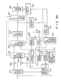
- An image signal is stored in a frame memory 301 in units of frames.
- the frame image data read out from the frame memory 301 is divided into a plurality of blocks by a dividing circuit 302, and the blocks are input to a significant block determining circuit 303.
- the image signal stored in the frame memory 301 is also input to a map forming circuit 313 and a background image processing section 314.
- the background image processing section 314 including a background memory detects an outline of a movement region, and determines a portion outside the contour as a background, so that its storage content of the memory 314 can be rewritten by the input frame image data.
- the map forming circuit 313 compares already stored background image data and a new input image signal, and separates the input frame image into a background image and a movement region, thus forming a map indicating a separating region.
- the formed map is used for the following movement detection, determination of a significant block, and conditional pixel replenishment.
- the map data is encoded by a contour encoding circuit 315, and is used for determining whether reception data is output or the content of the background memory is output when it is decoded by at the reception side.
- An encoding method using the map data can be used in an encoding circuit 306.
- the significant block detecting circuit 303 which receives the map data determines whether an input block is present outside or inside the contour, or extends across the contour. When the block is present outside the contour, the circuit 303 determines the block as an insignificant block, and inhibits transfer of the block to the next stage. Otherwise, the input block is determined as a significant block, and is transferred to a following differential circuit 304 and a motion vector detecting circuit 307.
- the motion vector detecting circuit 307 receive the significant block and the map data, and determines an optimal motion vector on the basis of immediately preceding frame image data stored in a first frame memory 311 in association with the significant block and the map data. The motion vector is obtained by the method described with reference to Fig. 26.
- the motion vector is supplied to a variable delay circuit 308 and a multiplexing circuit 319.
- the variable delay circuit 308 reads out a block having an offset corresponding to the vector from the first frame memory 311, and supplies the readout block to the differential circuit 304 and a block memory 322.
- the differential circuit 304 calculates a predictor error between the input block and a motion-vector-detected predictor block. A difference of a position corresponding to the movement region of the input block in the predictor error is evaluated by a conditional pixel replenishment determining circuit 305.
- the conditional pixel replenishment determining circuit 305 determines that the input block requires conditional pixel replenishment, and outputs a replenishment determination signal to the multiplexing circuit 319 and the block memory 322. In response to this signal, the storage content of the block memory 322 is transferred to a second frame memory 312, thus interrupting transfer of the predictor error to the next stage. If the error is larger than the predetermined value, the predictor error is supplied to the encoding circuit 306 and is encoded. The encoded predictor error data is supplied to the multiplexing circuit 319. The data is locally decoded by a decoding circuit 309, and is stored in the second frame memory 312. The frame image data stored in the second frame memory 312 is transferred to the first frame memory 311, and is referred to during movement detection.
- the background data is transmitted at the beginning of communication or only when a background transmission request is sent from the transmission side.
- the background image processing section 314 selects only a background portion from the input frame, and is always updated.
- An external recording device 316 comprises a rewritable recording device such as a floppy disk, cassette tape, IC card, VTR, DAT, or the like or a compact and easily replaceable memory such as a non-rewritable recording device, e.g., an optical card. CD-ROM, or the like, and its handler, and stores another background used as a substitute of a true background.
- the content of the background can be easily formed by a user using a floppy disk or video equipment.
- a selection circuit 317 determines based on setting at the transmission side whether the content of the background memory 314 or the external recording device 316 is transmitted as a background.
- the selected background data is encoded by a background encoding circuit 318. In this case, if the background data is encoded in advance, the background encoding circuit 318 can be omitted.
- the movement region data from the multiplexing circuit 319 and the background data output from the background encoding circuit 318 are supplied to an output switching circuit 320.
- the output switching circuit 320 is switched to a background output side at the beginning of communication and when the background transmission request is sent from the transmission side; otherwise, the output switching circuit 320 is switched to a movement region output side.
- the following method is known.
- a kind of security function can be proposed. That is, when a receiving station receives an incoming call, it selects a background output from the external recording device 316. After a calling party is confirmed, the receiving station selects the background data stored in the background image memory of section 314, and then outputs a background transmission request to perform normal speech communication. In this case, movement region data can be inhibited from being transmitted from call incoming to the second background transmission request.
- Whether a signal is a movement region or background signal can be determined by a method of wiring data representing a movement region or background in a frame header added to each frame at the transmission side.
- the output switching circuit 320 starts reading of a movement region signal, and when the next frame header arrives, it switches a movement region transmission selection bit to a background transmission selection bit. Thereafter, the circuit 320 sends background data, and supplies write inhibition data to the second frame memory 312.
- transmission of movement region data is restarted. In this case, movement region data 2 and 3 are not transmitted.
- the background image processing section 314 shown in Fig. 43 is the same as that shown in Fig. 31, and the operation principle of this section is the same as that described with reference to Fig. 35.
- the operation of the contour detecting circuit 247 has already been described with reference to Figs. 36 and 37.
- Data transmitted from a transmitting unit is temporarily stored in a buffer 401, and is then input to a selection circuit 402.
- the selection circuit 402 selects a destination of received data in accordance with whether the received data is movement region data or background data.
- the background data is sent to a background decoding circuit 412 and is decoded.
- the decoded data is stored in a background image memory 413, and thereafter, the content of the background image memory 413 is always output to a synthesizing circuit 414.
- the movement region data is separated into outline data, encoded data in units of Nocks, motion vector data, and conditional pixel replenishment data by a demultiplexing circuit 403.
- the demultiplexed data are respectively input to a contour decoding circuit 406, a decoding circuit 404, a variable delay circuit 410, and a write control circuit 411.
- the encoded data is decoded by the decoding circuit 404 in units of blocks, and the decoded data-is output to an adder 405.
- the motion vector data is input to the variable delay circuit 410, and a frame memory 409 then selects a block corresponding to the motion vector and inputs it to the adder 405.
- the adder 405 adds the block data and the decoded block data, and outputs sum data to the write control circuit 411 and the synthesizing circuit 414.
- the contour data is decoded by the contour decoding circuit 406, and is input to a map forming circuit 407 for forming a map.
- the map data is supplied to the write control circuit 411, and is used for calculating an address of a significant block.
- the map data is also supplied to the synthesizing circuit 414.
- the synthesizing circuit 414 assigns the movement region data output from the adder 405 and the background data output from the background memory 413 to a movement region portion and a background region portion, respectively, thus synthesizing one frame image.
- the write control circuit 411 calculates an address of a significant block in accordance with the map data input from the map forming circuit 407, and controls write access to a frame memory 408 with reference to the conditional pixel replenishment pixel supplement data. More specifically, when an input block is subjected to pixel supplement, the data output from the variable delay circuit 410 is written in the frame memory 408. When the input block is not subjected to conditional pixel replenishment, the data output from the adder 405 is written in the frame memory 408. The data in the frame memory 408 is transferred to the frame memory 409 in synchronism with a frame.
- TV cameras 300 and 350 are arranged to have the same horizontal coordinate system and parallel optical axes.
- Image signals output from the TV cameras 300 and 350 are input to a distance measuring circuit 352 through frame memories 301 and 351.
- the distance measuring circuit 352 matches corresponding points of the two images. In this matching, distances between corresponding points, in both the images are measured by, e.g., a three-dimensional measuring method described in "Image Processing Handbook (Morio Onoe)", Chapter 17.
- a map forming circuit 353 forms a map representing movement and background region data. In this embodiment, no background data is sent at all, and a fixed pattern designated by a background code generator 354 is displayed as, a background of a receiving section.
- FIG. 47 A receiving section corresponding to the transmitting section shown in Fig. 46 will be described below with reference to Fig. 47.
- the same reference numerals in Fig. 47 denote the same parts as in the embodiment shown in Fig. 45, and a detailed description thereof will be omitted.
- a background code. sent from the transmitting section is supplied to a background pattern generator 420 through a buffer 401 and a selection circuit 402.
- the background pattern generator 420 selects background data corresponding to the background code from a ROM 421, and supplies the selected background pattern to a synthesizing circuit 414.
- the background codes and background images have a correspondence shown in Fig. 48. Background codes "00", “01”, “10”, and “11” respectively correspond to a gray background, blue background, black & white stripe background, and predetermined landscape background, and a background image is selected in accordance with a code.
- an input frame fetched by a frame memory 501 is divided into a plurality of blocks by a dividing circuit 502, and the blocks update a content of a background memory 504.
- a map representing movement and background regions is formed by a map forming circuit 503.
- a frame memory 506 stores movement image data read out from an .external recording device 505 for storing image data including background data.
- the external recording device 505 comprises a recording device, e.g., a VTR (Video Tape Recorder), for outputting image data having the same format as that of frame image data input to the frame memory 501.
- Frame image data read out from the frame memory 506 is divided into a plurality of blocks by a dividing circuit 507.
- the block image data output from the dividing circuits 502 and 507 and map data output from the map forming circuit 503 are input to a background change circuit 508.
- a background change control circuit 514 determines whether the transmitting section receives background data from a camera or the external recording device 505 or the entire-image is received from the external recordtng device 505, and outputs control data to the background change circuit 508.
- the background change circuit 508 is designated to obtain background data from the external recording device 505 by the control data
- pixels, which are designated as a background by the map, of the block input from the dividing circuit 502 are substituted with pixels at the same positions of the input block output from the dividing circuit 507, and the changed pixels are output to an encoding circuit 509.
- An encoding operation in the encoding circuit 509 is performed in the same manner as in the above embodiment.
- An input image signal is divided into a plurality of blocks and the blocks are supplied to differential circuits 602 and 603 and a motion vector detecting circuit 614.
- the differential circuit 602 calculates a difference between a block signal and a motion-compensated inter-frame predictor signal output from the motion vector detecting circuit 614, and outputs predictor error data.
- the differential circuit 603 calculates a difference between an input block signal and a background predictor signal read out from a background predictor memory 615, and outputs predictor error data. These error data are input to a predictor selection circuit 604, and an RMS (root mean square) valve or absolute mean value is calculated therefrom. Thus, one of the two predictor errors is selected.
- RMS root mean square
- the selected predictor error data is supplied to a multiplexing circuit 607 and a selection circuit 608.
- the predictor selection circuit 604 selects the moiton-compensated inter-frame prediction signal
- the motion vector data output from the motion vector detecting circuit 614 is input to the multiplexing circuit 607.
- a transmission selection circuit 605 determines in accordance with a control signal output from a control signal generator 619 whether the predictor error signal or the content of a background memory 617 is sent to an encoding circuit 606. At the same time, a signal indicating a selected signal is supplied to the multiplexing circuit 607.
- an input signal is encoded, and the encoded signal is input to the multiplexing circuit 607 and a decoding circuit 610.
- the multiplexing circuit 607 adds, to the encoded signal in units of frames, header data which is output from the transmission selection circuit 605 and indicates that the predictor error is transmitted or the content of the background memory is transmitted. Furthermore, the multiplexing circuit 607 adds, to the encoded signal, movement vector data, which is output from the predictor selection circuit 604 and indicates that a motion-compensated predictor or a background predictor is selected in units of blocks.
- An output from the multiplexing circuit 607 is temporarily stored in a buffer memory for synchronizing an output timing, and is then transmitted to a receiving section.
- the prediction signal selected by the selection circuit 608 is selected by a selection signal output from the predictor selection circuit 604, and a signal output from a selected one of the motion vector detecting circuit 614 or the background predictor memory 615 is stored in a block memory 609 in units of blocks.
- a signal decoded by the decoding circuit 610 and a signal read out from the block memory 609 are added to each other by an adder 611, and the sum signal is output as a signal having the same format as that of a decoded signal in the receiving section.
- the decoded signal is written in a frame memory 612 through a gate circuit 620 which is opened/closed under the control of the control signal generator 619.
- a signal output from the adder 611 is the same present frame signal as that in the receiving section, and is stored in the frame memory 612. In synchronism with this frame signal, the content of the frame memory 612 is transferred to a frame memory 613, and the content of the memory 613 is referred to by the motion vector detecting circuit 614 for storing the content of the immediately preceding frame.
- the motion vector detecting circuit 614 detects a movement region on the basis of a block input from the dividing circuit 601 and a frame signal read out from the frame memory 613, and outputs a motion-compensated predictor block to the differential circuit 602 and the selection circuit 608 and outputs a movement vector to the predictor selection circuit 604.
- the signal output from the decoding circuit 610 is stored in the background predictor memory 615 through the other gate circuit 616.
- the content of the background predictor memory 615 is the same as that of a background memory arranged in the receiving section. More specifically, only when the content of the background predictor memory 615 is rewritten by the content of the background memory 617, the gate circuit 616 is opened in response to the control signal from the control signal generator 619, and a background image is sequentially stored. More specifically, the control signal generator 619 detects the amount of the content of a buffer memory 618. When the amount of the content is small, the control signal generator 619 outputs a first control signal indicating that the content of the background memory 617 is transmitted.
- the control signal generator 619 detects a header indicating transmission of data from the background memory on the basis of the content of the buffer memory 618, opens the gate circuit 616 in response to this detection, and outputs a second control signal indicating that the content of the background predictor memory 615 is rewritten with the content of the background memory 617.
- the background memory 617 is the same as that in the embodiment shown in Fig. 45, and. a detailed description thereof will be omitted.
- a receiving section will be deserilbed below with reference to Fig. 51.
- a signal transmitted from the, transmitting section is temporarily stored in a buffer mermory 681, and is separated into an image signal, a reception selection signal, and a predictor selection aignal by a separating circuit 682.
- the image signal is decoded by a decoding circuit 683, and the decoded signal is input to a selection circuit 684.
- the reception selection signal is input to a reception selection control circuit 686 the recpetion selection control circuit 686 detects whether or not the presently receiving signal is data for updating a background memory.
- the predictor selection signal is separated into a motion vector signal used for motion vector detection, and a predictor selection signal by a predictor selection control circuit 687, and these signals are respectively input to a motion vector detecting circuit 689 and a predictor selection circuit 690.
- the motion vector is not included in a transmission signal.
- the reception selection control circuit 686 determines that the presently receiving data is data for updating the background memory, it outputs a control signal to the selection circuit 684.
- the selection circuit 684 writes an image signal in a background predictor memory 688.
- the content of a background predictor memory 688 is the same as that of the background predictor memory 615 shown in Fig. 50.
- a background image is sequentially completed in the background predictor memory 688.
- the predictor selection circuit 690 selects the content of the background predictor memory 688 or the motion-compensated-detected predictor signal obtained by the motion vector detecting circuit 689 on the basis of the immediately preceding frame signal read out from a frame memory 692 in accordance with a selection signal output from the predictor selection control circuit 687.
- the selected signal is input to an adder 685, and is added to the output signal from the selection circuit 684.
- the sum signal from the adder 685 is input to a monitor, and is displayed thereon.
- the sum signal is stored in a frame memory 691 in units of blocks.
- the image signal stored in the frame memory 691 is stored in a frame memory 692 in units of frames.
Applications Claiming Priority (8)
| Application Number | Priority Date | Filing Date | Title |
|---|---|---|---|
| JP63037434A JPH01213086A (ja) | 1988-02-22 | 1988-02-22 | 画像符号化方式 |
| JP37434/88 | 1988-02-22 | ||
| JP63132301A JPH01198884A (ja) | 1987-10-14 | 1988-05-30 | 画像伝送装置 |
| JP132301/88 | 1988-05-30 | ||
| JP63194520A JPH0244881A (ja) | 1988-08-05 | 1988-08-05 | 動画像符号化方式 |
| JP194520/88 | 1988-08-05 | ||
| JP232216/88 | 1988-09-19 | ||
| JP63232216A JPH0281590A (ja) | 1988-09-19 | 1988-09-19 | 動画像符号化方式 |
Publications (2)
| Publication Number | Publication Date |
|---|---|
| EP0330455A2 true EP0330455A2 (fr) | 1989-08-30 |
| EP0330455A3 EP0330455A3 (fr) | 1990-07-04 |
Family
ID=27460415
Family Applications (1)
| Application Number | Title | Priority Date | Filing Date |
|---|---|---|---|
| EP89301739A Withdrawn EP0330455A3 (fr) | 1988-02-22 | 1989-02-22 | Dispositif de codage d'images |
Country Status (2)
| Country | Link |
|---|---|
| US (1) | US4951140A (fr) |
| EP (1) | EP0330455A3 (fr) |
Cited By (36)
| Publication number | Priority date | Publication date | Assignee | Title |
|---|---|---|---|---|
| EP0411076A1 (fr) * | 1989-01-16 | 1991-02-06 | iSight, Inc. | Systeme d'imagerie video |
| EP0449555A2 (fr) * | 1990-03-26 | 1991-10-02 | Kabushiki Kaisha Toshiba | Dispositif de codage d'images |
| EP0452627A1 (fr) * | 1990-03-19 | 1991-10-23 | Mitsubishi Denki Kabushiki Kaisha | Procédé d'analyse et appareil pour filmer des phénomènes rapides |
| DE4015390A1 (de) * | 1990-05-14 | 1991-11-21 | Nokia Unterhaltungselektronik | Verfahren zum berechnen des inhalts eines zwischenbildes zu jeweils zwei aufeinanderfolgenden monitorbildern |
| EP0473384A2 (fr) * | 1990-08-31 | 1992-03-04 | Sony Corporation | Dispositif de codage de signaux d'image digitaux |
| EP0476603A2 (fr) * | 1990-09-20 | 1992-03-25 | Nec Corporation | Méthode et dispositif pour le codage d'un signal d'image mobile |
| FR2672407A1 (fr) * | 1991-01-31 | 1992-08-07 | Graphics Communication Tech | Dispositif de codage pour des images en mouvement. |
| FR2673014A1 (fr) * | 1991-02-15 | 1992-08-21 | Graphics Communication Tech | Dispositif de codage de signal d'image. |
| EP0514053A2 (fr) * | 1991-05-08 | 1992-11-19 | Nec Corporation | Codage de signal d'image animée |
| EP0534504A2 (fr) * | 1989-02-14 | 1993-03-31 | Mitsubishi Denki Kabushiki Kaisha | Dispositif pour coder et décoder des signaux d'image |
| EP0574244A2 (fr) * | 1992-06-10 | 1993-12-15 | Canon Kabushiki Kaisha | Procédé et appareil de codage |
| EP0577377A2 (fr) * | 1992-06-29 | 1994-01-05 | Canon Kabushiki Kaisha | Appareil, méthode et système de traitement d'image |
| EP0579319A2 (fr) * | 1992-07-16 | 1994-01-19 | Philips Electronics Uk Limited | Poursuite d'un objet en mouvement |
| EP0581593A1 (fr) * | 1992-07-31 | 1994-02-02 | Canon Kabushiki Kaisha | Appareil et procédé de communication d'images |
| EP0593275A1 (fr) * | 1992-10-15 | 1994-04-20 | Sharp Kabushiki Kaisha | Dispositif de codage de signal d'image pour réduire la quantité d'information dans l'image transmise |
| EP0635983A2 (fr) * | 1993-07-19 | 1995-01-25 | AT&T Corp. | Méthode et moyen pour détecter des personnes dans des séquences d'images |
| EP0674448A2 (fr) * | 1994-03-25 | 1995-09-27 | Nec Corporation | Reproduction d'images vidéo à haute vitesse |
| EP0695096A1 (fr) * | 1994-07-27 | 1996-01-31 | Sony Corporation | Dispositif pour détecter des vecteurs de mouvement et à coder des signals d'image |
| EP0696144A3 (fr) * | 1994-08-02 | 1996-04-24 | Canon Kk | Appareil de prise de vues multi-lentilles comprenant une unité d'extraction des points correspondants |
| EP0708563A2 (fr) * | 1994-10-19 | 1996-04-24 | Matsushita Electric Industrial Co., Ltd. | Dispositif pour le codage/décodage d'image |
| EP0731608A2 (fr) * | 1995-03-10 | 1996-09-11 | Sharp Kabushiki Kaisha | Codeur et décodeur d'image avec sélection d'une région |
| EP0739142A2 (fr) * | 1990-02-26 | 1996-10-23 | Sony Corporation | Méthode et dispositif pour coder un signal vidéo |
| US5570434A (en) * | 1990-09-05 | 1996-10-29 | U.S. Philips Corporation | Circuit arrangement for recognizing a human face |
| EP0684736A3 (fr) * | 1994-05-27 | 1998-02-11 | AT&T Corp. | Codage de séquences vidéo à faibles débits de bits assisté par un modèle |
| EP0824824A1 (fr) * | 1995-05-08 | 1998-02-25 | Kabushiki Kaisha Toshiba | Systeme de modification de trames video codees |
| EP0891075A2 (fr) * | 1997-06-09 | 1999-01-13 | Seiko Epson Corporation | Appareil et procédé de traitement d'images, et dispositif et procédé d'évaluation d'images |
| EP0734166A3 (fr) * | 1995-03-20 | 1999-03-24 | Daewoo Electronics Co., Ltd | Appareil de codage d'un signal d'image ayant un objet fixe |
| EP1051038A2 (fr) * | 1993-07-12 | 2000-11-08 | Sony Corporation | Traitement de données vidéo numériques |
| EP1162848A2 (fr) * | 2000-06-09 | 2001-12-12 | Mitsubishi Denki Kabushiki Kaisha | Dispositif de codage d'images |
| EP1170956A2 (fr) * | 2000-06-06 | 2002-01-09 | Kabushiki Kaisha Office Noa | Procédé et système pour la compression de l'information des images animées |
| EP1259081A2 (fr) * | 1992-09-16 | 2002-11-20 | Fujitsu Limited | Codage de données continues d'image |
| WO2003107677A1 (fr) * | 2002-06-12 | 2003-12-24 | British Telecommunications Public Limited Company | Pretraitement video |
| WO2004051981A3 (fr) * | 2002-11-29 | 2005-07-07 | Sony Uk Ltd | Camera video |
| KR100525678B1 (en) * | 2000-06-06 | 2005-11-03 | Method and system for compressing motion image information | |
| US7085424B2 (en) | 2000-06-06 | 2006-08-01 | Kobushiki Kaisha Office Noa | Method and system for compressing motion image information |
| WO2012072727A1 (fr) | 2010-12-03 | 2012-06-07 | Biotie Therapies Gmbh | Modification cristalline du n(3,5-dichloropyridin-4-yl)-[1-(4-fluorobenzyl)-7-azaindol-3-yl)]glyoxylamide servant d'inhibiteur de la pde4 |
Families Citing this family (94)
| Publication number | Priority date | Publication date | Assignee | Title |
|---|---|---|---|---|
| US5481737A (en) * | 1989-05-30 | 1996-01-02 | Fujitsu Limited | Image data quantizing circuit with a memory for storing unquantized and quantized image data |
| IT1232109B (it) * | 1989-06-21 | 1992-01-23 | Cselt Centro Studi Lab Telecom | Procedimento e dispositivo di riconoscimento del contorno di immagini in movimento |
| JP2633694B2 (ja) * | 1989-08-25 | 1997-07-23 | フジテック 株式会社 | 人数検出装置 |
| JP3159309B2 (ja) * | 1989-09-27 | 2001-04-23 | ソニー株式会社 | 映像信号符号化方法及び映像信号符号化装置 |
| JP2953712B2 (ja) * | 1989-09-27 | 1999-09-27 | 株式会社東芝 | 移動物体検知装置 |
| JPH082107B2 (ja) * | 1990-03-02 | 1996-01-10 | 国際電信電話株式会社 | 動画像のハイブリッド符号化方法及びその装置 |
| US5148477A (en) * | 1990-08-24 | 1992-09-15 | Board Of Regents Of The University Of Oklahoma | Method and apparatus for detecting and quantifying motion of a body part |
| JPH0771288B2 (ja) * | 1990-08-24 | 1995-07-31 | 神田通信工業株式会社 | 自動視野調整方法及び装置 |
| US5115309A (en) * | 1990-09-10 | 1992-05-19 | At&T Bell Laboratories | Method and apparatus for dynamic channel bandwidth allocation among multiple parallel video coders |
| JPH04256298A (ja) * | 1991-02-08 | 1992-09-10 | Toshiba Corp | 動画像符号化装置 |
| US6005627A (en) * | 1991-05-31 | 1999-12-21 | Kabushiki Kaisha Toshiba | Video coding apparatus |
| US5986713A (en) * | 1991-05-31 | 1999-11-16 | Kabushiki Kaisha Toshiba | Video coding apparatus using inter-field prediction |
| US5317397A (en) * | 1991-05-31 | 1994-05-31 | Kabushiki Kaisha Toshiba | Predictive coding using spatial-temporal filtering and plural motion vectors |
| JP2868045B2 (ja) * | 1991-10-25 | 1999-03-10 | 日本電気株式会社 | 動画像信号符号化装置 |
| KR940010241B1 (ko) * | 1991-12-14 | 1994-10-22 | 산성전자 주식회사 | 이동 벡터 검출 방법 |
| US5806072A (en) * | 1991-12-20 | 1998-09-08 | Olympus Optical Co., Ltd. | Electronic imaging apparatus having hierarchical image data storage structure for computer-compatible image data management |
| US6965644B2 (en) * | 1992-02-19 | 2005-11-15 | 8×8, Inc. | Programmable architecture and methods for motion estimation |
| US5293229A (en) * | 1992-03-27 | 1994-03-08 | Matsushita Electric Corporation Of America | Apparatus and method for processing groups of fields in a video data compression system |
| US5337085A (en) * | 1992-04-10 | 1994-08-09 | Comsat Corporation | Coding technique for high definition television signals |
| JPH05308630A (ja) * | 1992-04-28 | 1993-11-19 | Victor Co Of Japan Ltd | 動きベクトル検出方法 |
| US5664029A (en) * | 1992-05-13 | 1997-09-02 | Apple Computer, Inc. | Method of disregarding changes in data in a location of a data structure based upon changes in data in nearby locations |
| US5444489A (en) * | 1993-02-11 | 1995-08-22 | Georgia Tech Research Corporation | Vector quantization video encoder using hierarchical cache memory scheme |
| EP1052589A3 (fr) * | 1993-02-17 | 2000-12-13 | Canon Kabushiki Kaisha | Méthode et dispositif d'impression de données codées |
| US5592228A (en) * | 1993-03-04 | 1997-01-07 | Kabushiki Kaisha Toshiba | Video encoder using global motion estimation and polygonal patch motion estimation |
| USRE43462E1 (en) | 1993-04-21 | 2012-06-12 | Kinya (Ken) Washino | Video monitoring and conferencing system |
| DE4405803C2 (de) * | 1994-02-23 | 1997-04-30 | Bosch Gmbh Robert | Verfahren zur Quellcodierung |
| JP3102260B2 (ja) * | 1994-03-31 | 2000-10-23 | 日本ビクター株式会社 | 動画像符号化装置 |
| US5512939A (en) * | 1994-04-06 | 1996-04-30 | At&T Corp. | Low bit rate audio-visual communication system having integrated perceptual speech and video coding |
| US5521634A (en) | 1994-06-17 | 1996-05-28 | Harris Corporation | Automatic detection and prioritized image transmission system and method |
| US5751377A (en) | 1994-11-04 | 1998-05-12 | Matsushita Electric Industrial Co., Ltd. | Picture coding apparatus and decoding apparatus |
| US5978514A (en) | 1994-11-10 | 1999-11-02 | Kabushiki Kaisha Toshiba | Image data coding and decoding system for efficiently compressing information using the shape and position of the image content |
| JP3258840B2 (ja) * | 1994-12-27 | 2002-02-18 | シャープ株式会社 | 動画像符号化装置および領域抽出装置 |
| US5802211A (en) * | 1994-12-30 | 1998-09-01 | Harris Corporation | Method and apparatus for transmitting and utilizing analog encoded information |
| US6020925A (en) * | 1994-12-30 | 2000-02-01 | Daewoo Electronics Co., Ltd. | Method and apparatus for encoding a video signal using pixel-by-pixel motion prediction |
| KR100209409B1 (ko) * | 1995-03-20 | 1999-07-15 | 전주범 | 물체 왜곡을 이용한 물체 기반 부호화 방법 및 장치 |
| JPH08256266A (ja) * | 1995-03-17 | 1996-10-01 | Mitsubishi Electric Corp | 画像符号化方式 |
| US5923786A (en) * | 1995-07-17 | 1999-07-13 | Sony Corporation | Method and device for encoding and decoding moving images |
| DE69618759T2 (de) * | 1995-09-06 | 2002-09-12 | Koninkl Philips Electronics Nv | Verfahren und system zur kodierung einer sequenz von segmentierten bildern , kodiertes signal und speichermedium, verfahren und system zur dekodierung des kodierten signals |
| US6307967B1 (en) | 1995-09-29 | 2001-10-23 | Kabushiki Kaisha Toshiba | Video coding and video decoding apparatus |
| US5883678A (en) * | 1995-09-29 | 1999-03-16 | Kabushiki Kaisha Toshiba | Video coding and video decoding apparatus for reducing an alpha-map signal at a controlled reduction ratio |
| US6754268B1 (en) | 1995-09-29 | 2004-06-22 | Kabushiki Kaisha Toshiba | Video coding and video decoding apparatus |
| US5745178A (en) * | 1996-01-22 | 1998-04-28 | Lucent Technologies Inc. | Global rate control for model-assisted coding of low bit rate video |
| US6415056B1 (en) * | 1996-01-22 | 2002-07-02 | Matsushita Electric Industrial, Co., Ltd. | Digital image encoding and decoding method and digital image encoding and decoding device using the same |
| US6577771B1 (en) | 1996-01-29 | 2003-06-10 | Matsushita Electric Industrial Co., Ltd. | Method for supplementing digital image with picture element, and digital image encoder and decoder using the same |
| US5778100A (en) * | 1996-03-08 | 1998-07-07 | Lucent Technologies Inc. | Method and apparatus for reducing the bit rate in a video object planes sequence coder |
| KR100209132B1 (ko) * | 1996-07-11 | 1999-07-15 | 전주범 | 블럭-기반 물체 윤곽 부호화 방법 |
| US6205253B1 (en) * | 1996-08-19 | 2001-03-20 | Harris Corporation | Method and apparatus for transmitting and utilizing analog encoded information |
| DE69713779T2 (de) * | 1996-09-12 | 2002-10-17 | Univ Bath | Objektorientiertes videosystem |
| US6654414B1 (en) * | 1996-11-12 | 2003-11-25 | Ibm Corporation | Video conferencing using camera environment panoramas |
| US5903673A (en) * | 1997-03-14 | 1999-05-11 | Microsoft Corporation | Digital video signal encoder and encoding method |
| US6584226B1 (en) * | 1997-03-14 | 2003-06-24 | Microsoft Corporation | Method and apparatus for implementing motion estimation in video compression |
| US5764306A (en) * | 1997-03-18 | 1998-06-09 | The Metaphor Group | Real-time method of digitally altering a video data stream to remove portions of the original image and substitute elements to create a new image |
| US6173069B1 (en) | 1998-01-09 | 2001-01-09 | Sharp Laboratories Of America, Inc. | Method for adapting quantization in video coding using face detection and visual eccentricity weighting |
| US6184858B1 (en) * | 1998-02-06 | 2001-02-06 | Compaq Computer Corporation | Technique for updating a background image |
| JP3560217B2 (ja) * | 1998-04-30 | 2004-09-02 | ソニー株式会社 | データ符号化装置、データ符号化方法及びデータ伝送方法 |
| US6546052B1 (en) * | 1998-05-29 | 2003-04-08 | Canon Kabushiki Kaisha | Image processing apparatus and method, and computer-readable memory |
| JP4142180B2 (ja) | 1998-10-29 | 2008-08-27 | 富士通株式会社 | 動きベクトル符号化装置および復号装置 |
| US20020051491A1 (en) * | 1998-11-20 | 2002-05-02 | Kiran Challapali | Extraction of foreground information for video conference |
| US6850565B2 (en) * | 1998-12-18 | 2005-02-01 | Intel Corporation | Real time bit rate control system |
| JP4208315B2 (ja) * | 1998-12-25 | 2009-01-14 | キヤノン株式会社 | データ通信制御装置及びその制御方法、データ通信システム、記録媒体 |
| GB2357650A (en) * | 1999-12-23 | 2001-06-27 | Mitsubishi Electric Inf Tech | Method for tracking an area of interest in a video image, and for transmitting said area |
| US20010017650A1 (en) * | 1999-12-23 | 2001-08-30 | Mitsubishi Denki Kabushiki Kaisha | Method and apparatus for transmitting a video image |
| JP2001266158A (ja) * | 2000-01-11 | 2001-09-28 | Canon Inc | 画像処理装置、画像処理システム、画像処理方法、及び記憶媒体 |
| AUPQ887100A0 (en) * | 2000-07-19 | 2000-08-10 | Dynamic Digital Depth Research Pty Ltd | Image processing and encoding techniques |
| JP4271378B2 (ja) * | 2001-01-30 | 2009-06-03 | 富士通株式会社 | 撮像装置 |
| US7321624B1 (en) * | 2001-03-16 | 2008-01-22 | Objectvideo, Inc. | Bit-rate allocation system for object-based video encoding |
| EP2302929B1 (fr) * | 2001-11-27 | 2015-03-25 | Samsung Electronics Co., Ltd. | Codage et décodage d'un flux de bits vidéo avec une interpolateur de coordonnées |
| US7130446B2 (en) * | 2001-12-03 | 2006-10-31 | Microsoft Corporation | Automatic detection and tracking of multiple individuals using multiple cues |
| US8780970B2 (en) * | 2001-12-21 | 2014-07-15 | Polycom, Inc. | Motion wake identification and control mechanism |
| KR100508119B1 (ko) * | 2003-03-14 | 2005-08-10 | 엘지전자 주식회사 | 영상데이터를 처리하는 장치 및 그 방법 |
| US8638846B1 (en) * | 2003-06-23 | 2014-01-28 | At&T Intellectual Property Ii, L.P. | Systems and methods for encoding and decoding video streams |
| KR100517906B1 (ko) * | 2003-11-27 | 2005-09-30 | (주) 멀티비아 | 모바일 디바이스용 동영상 압축 방법 |
| US20050128054A1 (en) | 2003-12-16 | 2005-06-16 | Jeff Glickman | Method, system, and apparatus to identify and transmit data to an image display |
| US7623728B2 (en) * | 2004-03-24 | 2009-11-24 | General Electric Company | Method and product for processing digital images |
| JP2006106897A (ja) * | 2004-09-30 | 2006-04-20 | Fujitsu Ltd | リーダライタおよびrfidシステム |
| JP2006109119A (ja) * | 2004-10-06 | 2006-04-20 | Omron Corp | 動画記録装置および動画再生装置 |
| JP2006338226A (ja) * | 2005-06-01 | 2006-12-14 | Hitachi Ltd | リモート操作システム |
| JP2007157063A (ja) * | 2005-12-08 | 2007-06-21 | Sony Corp | 画像処理装置及び画像処理方法、並びにコンピュータ・プログラム |
| US8265349B2 (en) * | 2006-02-07 | 2012-09-11 | Qualcomm Incorporated | Intra-mode region-of-interest video object segmentation |
| US8265392B2 (en) * | 2006-02-07 | 2012-09-11 | Qualcomm Incorporated | Inter-mode region-of-interest video object segmentation |
| US8150155B2 (en) | 2006-02-07 | 2012-04-03 | Qualcomm Incorporated | Multi-mode region-of-interest video object segmentation |
| FR2917210B1 (fr) * | 2007-06-08 | 2011-07-22 | Sagem Comm | Systeme et procede de codage video |
| JP4471039B2 (ja) * | 2008-02-14 | 2010-06-02 | 日本電気株式会社 | 移動ベクトル検出装置 |
| JP4539729B2 (ja) * | 2008-02-15 | 2010-09-08 | ソニー株式会社 | 画像処理装置、カメラ装置、画像処理方法、およびプログラム |
| CN101953165A (zh) * | 2008-04-18 | 2011-01-19 | 电子地图有限公司 | 使用激光扫描的点云来形成选择性压缩遮掩的方法 |
| WO2011024602A1 (fr) * | 2009-08-26 | 2011-03-03 | シャープ株式会社 | Dispositif de codage d'image et dispositif de décodage d'image |
| US8515124B2 (en) * | 2010-02-04 | 2013-08-20 | Electronics And Telecommunications Research Institute | Method and apparatus for determining fake image |
| US8842723B2 (en) * | 2011-01-03 | 2014-09-23 | Apple Inc. | Video coding system using implied reference frames |
| JP5801614B2 (ja) * | 2011-06-09 | 2015-10-28 | キヤノン株式会社 | 画像処理装置、画像処理方法 |
| JP5839848B2 (ja) | 2011-06-13 | 2016-01-06 | キヤノン株式会社 | 画像処理装置、画像処理方法 |
| CN109089120A (zh) | 2011-09-06 | 2018-12-25 | 英特尔公司 | 分析辅助编码 |
| US9571723B2 (en) * | 2011-11-18 | 2017-02-14 | National Science Foundation | Automatic detection by a wearable camera |
| US9538081B1 (en) * | 2013-03-14 | 2017-01-03 | Amazon Technologies, Inc. | Depth-based image stabilization |
| JP6457248B2 (ja) * | 2014-11-17 | 2019-01-23 | 株式会社東芝 | 画像復号装置、画像符号化装置および画像復号方法 |
Citations (4)
| Publication number | Priority date | Publication date | Assignee | Title |
|---|---|---|---|---|
| EP0022713A1 (fr) * | 1979-07-09 | 1981-01-21 | Jean Pierre Temime | Installation de codage et de décodage d'un signal visiophonique numérique |
| WO1987003768A1 (fr) * | 1984-06-08 | 1987-06-18 | Valtion Teknillinen Tutkimuskeskus | Procede et appareil permettant de detecter les zones d'images les plus intensement modifiees dans un signal video en direct |
| US4683494A (en) * | 1984-08-13 | 1987-07-28 | Nec Corporation | Inter-frame predictive coding apparatus for video signal |
| WO1988009101A1 (fr) * | 1987-05-06 | 1988-11-17 | British Telecommunications Public Limited Company | Traitement d'images video |
Family Cites Families (1)
| Publication number | Priority date | Publication date | Assignee | Title |
|---|---|---|---|---|
| US4494144A (en) * | 1982-06-28 | 1985-01-15 | At&T Bell Laboratories | Reduced bandwidth video transmission |
-
1989
- 1989-02-22 EP EP89301739A patent/EP0330455A3/fr not_active Withdrawn
- 1989-02-22 US US07/313,941 patent/US4951140A/en not_active Expired - Lifetime
Patent Citations (4)
| Publication number | Priority date | Publication date | Assignee | Title |
|---|---|---|---|---|
| EP0022713A1 (fr) * | 1979-07-09 | 1981-01-21 | Jean Pierre Temime | Installation de codage et de décodage d'un signal visiophonique numérique |
| WO1987003768A1 (fr) * | 1984-06-08 | 1987-06-18 | Valtion Teknillinen Tutkimuskeskus | Procede et appareil permettant de detecter les zones d'images les plus intensement modifiees dans un signal video en direct |
| US4683494A (en) * | 1984-08-13 | 1987-07-28 | Nec Corporation | Inter-frame predictive coding apparatus for video signal |
| WO1988009101A1 (fr) * | 1987-05-06 | 1988-11-17 | British Telecommunications Public Limited Company | Traitement d'images video |
Cited By (89)
| Publication number | Priority date | Publication date | Assignee | Title |
|---|---|---|---|---|
| EP0411076A1 (fr) * | 1989-01-16 | 1991-02-06 | iSight, Inc. | Systeme d'imagerie video |
| EP0411076A4 (en) * | 1989-01-16 | 1993-05-05 | Zeevi, Yehoshua Y | Video imaging system |
| EP0534504A3 (en) * | 1989-02-14 | 1993-06-09 | Mitsubishi Denki Kabushiki Kaisha | Picture signal encoding and decoding apparatus |
| EP0534504A2 (fr) * | 1989-02-14 | 1993-03-31 | Mitsubishi Denki Kabushiki Kaisha | Dispositif pour coder et décoder des signaux d'image |
| EP0739143A2 (fr) * | 1990-02-26 | 1996-10-23 | Sony Corporation | Méthode et dispositif pour coder un signal vidéo |
| EP0739142A3 (fr) * | 1990-02-26 | 1996-12-18 | Sony Corp | Méthode et dispositif pour coder un signal vidéo |
| EP0739142A2 (fr) * | 1990-02-26 | 1996-10-23 | Sony Corporation | Méthode et dispositif pour coder un signal vidéo |
| EP0739143A3 (fr) * | 1990-02-26 | 1996-12-18 | Sony Corp | Méthode et dispositif pour coder un signal vidéo |
| EP0452627A1 (fr) * | 1990-03-19 | 1991-10-23 | Mitsubishi Denki Kabushiki Kaisha | Procédé d'analyse et appareil pour filmer des phénomènes rapides |
| EP0449555A3 (en) * | 1990-03-26 | 1992-11-25 | Kabushiki Kaisha Toshiba | Image encoding apparatus |
| EP0449555A2 (fr) * | 1990-03-26 | 1991-10-02 | Kabushiki Kaisha Toshiba | Dispositif de codage d'images |
| DE4015390A1 (de) * | 1990-05-14 | 1991-11-21 | Nokia Unterhaltungselektronik | Verfahren zum berechnen des inhalts eines zwischenbildes zu jeweils zwei aufeinanderfolgenden monitorbildern |
| EP0473384A2 (fr) * | 1990-08-31 | 1992-03-04 | Sony Corporation | Dispositif de codage de signaux d'image digitaux |
| US5241381A (en) * | 1990-08-31 | 1993-08-31 | Sony Corporation | Video signal compression using 2-d adrc of successive non-stationary frames and stationary frame dropping |
| EP0473384A3 (en) * | 1990-08-31 | 1993-03-03 | Sony Corporation | Coding apparatus for digital image signals |
| US5570434A (en) * | 1990-09-05 | 1996-10-29 | U.S. Philips Corporation | Circuit arrangement for recognizing a human face |
| EP0476603A2 (fr) * | 1990-09-20 | 1992-03-25 | Nec Corporation | Méthode et dispositif pour le codage d'un signal d'image mobile |
| EP0476603A3 (en) * | 1990-09-20 | 1993-06-02 | Nec Corporation | Method and apparatus for coding moving image signal |
| US5253054A (en) * | 1991-01-31 | 1993-10-12 | Graphics Communication Technologies Ltd. | Frame skip encoding apparatus for moving images |
| FR2672407A1 (fr) * | 1991-01-31 | 1992-08-07 | Graphics Communication Tech | Dispositif de codage pour des images en mouvement. |
| FR2673014A1 (fr) * | 1991-02-15 | 1992-08-21 | Graphics Communication Tech | Dispositif de codage de signal d'image. |
| EP0514053A3 (en) * | 1991-05-08 | 1993-06-09 | Nec Corporation | Encoding of motion picture signal |
| EP0514053A2 (fr) * | 1991-05-08 | 1992-11-19 | Nec Corporation | Codage de signal d'image animée |
| EP0574244A2 (fr) * | 1992-06-10 | 1993-12-15 | Canon Kabushiki Kaisha | Procédé et appareil de codage |
| US5956153A (en) * | 1992-06-10 | 1999-09-21 | Canon Kabushiki Kaisha | Coding method and apparatus |
| EP0574244A3 (en) * | 1992-06-10 | 1994-08-10 | Canon Kk | Coding method and apparatus |
| EP0577377A3 (en) * | 1992-06-29 | 1994-08-31 | Canon Kk | Image processing apparatus and method, and system thereof |
| EP0577377A2 (fr) * | 1992-06-29 | 1994-01-05 | Canon Kabushiki Kaisha | Appareil, méthode et système de traitement d'image |
| US5517246A (en) * | 1992-06-29 | 1996-05-14 | Canon Kabushiki Kaisha | Image processing apparatus and method, and system thereof |
| EP0579319A3 (fr) * | 1992-07-16 | 1994-08-31 | Philips Electronics Uk Ltd | |
| EP0579319A2 (fr) * | 1992-07-16 | 1994-01-19 | Philips Electronics Uk Limited | Poursuite d'un objet en mouvement |
| EP0581593A1 (fr) * | 1992-07-31 | 1994-02-02 | Canon Kabushiki Kaisha | Appareil et procédé de communication d'images |
| US5666154A (en) * | 1992-07-31 | 1997-09-09 | Canon Kabushiki Kaisha | Image communication apparatus and method therefor |
| EP1271962A1 (fr) * | 1992-09-16 | 2003-01-02 | Fujitsu Limited | Méthode et dispositif de codage de données d'image |
| EP1259081A3 (fr) * | 1992-09-16 | 2002-12-04 | Fujitsu Limited | Codage de données continues d'image |
| EP1259081A2 (fr) * | 1992-09-16 | 2002-11-20 | Fujitsu Limited | Codage de données continues d'image |
| EP0593275A1 (fr) * | 1992-10-15 | 1994-04-20 | Sharp Kabushiki Kaisha | Dispositif de codage de signal d'image pour réduire la quantité d'information dans l'image transmise |
| EP1051038A3 (fr) * | 1993-07-12 | 2005-05-11 | Sony Corporation | Traitement de données vidéo numériques |
| EP1130922A2 (fr) * | 1993-07-12 | 2001-09-05 | Sony Corporation | Traitement de données video numériques |
| EP1051038A2 (fr) * | 1993-07-12 | 2000-11-08 | Sony Corporation | Traitement de données vidéo numériques |
| EP1130922A3 (fr) * | 1993-07-12 | 2005-05-11 | Sony Corporation | Traitement de données video numériques |
| EP0635983A2 (fr) * | 1993-07-19 | 1995-01-25 | AT&T Corp. | Méthode et moyen pour détecter des personnes dans des séquences d'images |
| EP0635983A3 (fr) * | 1993-07-19 | 1995-04-26 | At & T Corp | Méthode et moyen pour détecter des personnes dans des séquences d'images. |
| US5987154A (en) * | 1993-07-19 | 1999-11-16 | Lucent Technologies Inc. | Method and means for detecting people in image sequences |
| EP0674448A2 (fr) * | 1994-03-25 | 1995-09-27 | Nec Corporation | Reproduction d'images vidéo à haute vitesse |
| EP1139671A3 (fr) * | 1994-03-25 | 2004-12-15 | Nec Corporation | Système de transmission d'images et appareil de reproduction d'images |
| EP1139671A2 (fr) * | 1994-03-25 | 2001-10-04 | Nec Corporation | Système de transmission d'images et appareil de reproduction d'images |
| US5847767A (en) * | 1994-03-25 | 1998-12-08 | Nec Corporation | Compact image transmission system and image reproducing device capable of reproducing a DCT-based code at a high speed without deterioration of picture quality |
| EP1139672A3 (fr) * | 1994-03-25 | 2004-12-15 | Nec Corporation | Sytème de transmission d'images et appareil de reproduction d'images |
| EP0674448A3 (fr) * | 1994-03-25 | 1997-03-05 | Nec Corp | Reproduction d'images vidéo à haute vitesse. |
| EP0684736A3 (fr) * | 1994-05-27 | 1998-02-11 | AT&T Corp. | Codage de séquences vidéo à faibles débits de bits assisté par un modèle |
| EP0695096A1 (fr) * | 1994-07-27 | 1996-01-31 | Sony Corporation | Dispositif pour détecter des vecteurs de mouvement et à coder des signals d'image |
| US5691774A (en) * | 1994-07-27 | 1997-11-25 | Sony Corporation | Apparatus for detecting motion vector and encoding picture signals |
| US6236748B1 (en) | 1994-08-02 | 2001-05-22 | Canon Kabushiki Kaisha | Compound eye image pickup device utilizing plural image sensors and plural lenses |
| EP0696144A3 (fr) * | 1994-08-02 | 1996-04-24 | Canon Kk | Appareil de prise de vues multi-lentilles comprenant une unité d'extraction des points correspondants |
| EP0708563A3 (fr) * | 1994-10-19 | 1999-05-06 | Matsushita Electric Industrial Co., Ltd. | Dispositif pour le codage/décodage d'image |
| EP0708563A2 (fr) * | 1994-10-19 | 1996-04-24 | Matsushita Electric Industrial Co., Ltd. | Dispositif pour le codage/décodage d'image |
| USRE37668E1 (en) | 1994-10-19 | 2002-04-23 | Matsushita Electric Industrial Co., Ltd. | Image encoding/decoding device |
| US5978515A (en) * | 1995-03-10 | 1999-11-02 | Sharp Kabushiki Kaisha | Image encoder and image decoder |
| EP0731608A2 (fr) * | 1995-03-10 | 1996-09-11 | Sharp Kabushiki Kaisha | Codeur et décodeur d'image avec sélection d'une région |
| EP0731608A3 (fr) * | 1995-03-10 | 1998-09-16 | Sharp Kabushiki Kaisha | Codeur et décodeur d'image avec sélection d'une région |
| EP1318682A3 (fr) * | 1995-03-10 | 2004-12-08 | Sharp Kabushiki Kaisha | Codeur d'images et décodeur d'images |
| EP0734166A3 (fr) * | 1995-03-20 | 1999-03-24 | Daewoo Electronics Co., Ltd | Appareil de codage d'un signal d'image ayant un objet fixe |
| EP0824824A1 (fr) * | 1995-05-08 | 1998-02-25 | Kabushiki Kaisha Toshiba | Systeme de modification de trames video codees |
| US5819004A (en) * | 1995-05-08 | 1998-10-06 | Kabushiki Kaisha Toshiba | Method and system for a user to manually alter the quality of previously encoded video frames |
| EP0824824A4 (fr) * | 1995-05-08 | 1998-09-09 | Toshiba Kk | Systeme de modification de trames video codees |
| US8681380B2 (en) | 1997-06-09 | 2014-03-25 | Seiko Epson Corporation | Image processing apparatus, an image processing method, a medium on which an image processing control program is recorded, an image evaluation device, an image evaluation method and a medium on which an image evaluation program is recorded |
| US7259894B2 (en) | 1997-06-09 | 2007-08-21 | Seiko Epson Corporation | Image processing apparatus, an image processing method, a medium on which an image processing control program is recorded, an image evaluation device, an image evaluation method and a medium on which an image evaluation program is recorded |
| US8553285B2 (en) | 1997-06-09 | 2013-10-08 | Seiko Epson Corporation | Image processing apparatus, an image processing method, a medium on which an image processing control program is recorded, an image evaluation device, an image evaluation method and a medium on which an image evaluation program is recorded |
| US7940426B2 (en) | 1997-06-09 | 2011-05-10 | Seiko Epson Corporation | Image processing apparatus, an image processing method, a medium on which an image processing control program is recorded, an image evaluation device, an image evaluation method and a medium on which an image evaluation program is recorded |
| EP2199973A3 (fr) * | 1997-06-09 | 2010-09-08 | Seiko Epson Corporation | Appareil et procédé de traitement d'images, et dispositif et procédé d'évaluation d'images |
| EP0891075A2 (fr) * | 1997-06-09 | 1999-01-13 | Seiko Epson Corporation | Appareil et procédé de traitement d'images, et dispositif et procédé d'évaluation d'images |
| US6738527B2 (en) | 1997-06-09 | 2004-05-18 | Seiko Epson Corporation | Image processing apparatus, an image processing method, a medium on which an image processing control program is recorded, an image evaluation device, and image evaluation method and a medium on which an image evaluation program is recorded |
| US8867099B2 (en) | 1997-06-09 | 2014-10-21 | Seiko Epson Corporation | Image processing apparatus, an image processing method, a medium on which an image processing control program is recorded, an image evaluation device, an image evaluation method and a medium on which an image evaluation program is recorded |
| US7755801B2 (en) | 1997-06-09 | 2010-07-13 | Seiko Epson Corporation | Image processing apparatus, an image processing method, a medium on which an image processing control program is recorded, an image evaluation device, an image evaluation method and a medium on which an image evaluation program is recorded |
| US7508548B2 (en) | 1997-06-09 | 2009-03-24 | Seiko Epson Corporation | Image processing method and image processing apparatus |
| EP0891075A3 (fr) * | 1997-06-09 | 2002-03-06 | Seiko Epson Corporation | Appareil et procédé de traitement d'images, et dispositif et procédé d'évaluation d'images |
| KR100525678B1 (en) * | 2000-06-06 | 2005-11-03 | Method and system for compressing motion image information | |
| US7085424B2 (en) | 2000-06-06 | 2006-08-01 | Kobushiki Kaisha Office Noa | Method and system for compressing motion image information |
| EP1170956A2 (fr) * | 2000-06-06 | 2002-01-09 | Kabushiki Kaisha Office Noa | Procédé et système pour la compression de l'information des images animées |
| EP1170956A3 (fr) * | 2000-06-06 | 2004-08-04 | Kabushiki Kaisha Office Noa | Procédé et système pour la compression de l'information des images animées |
| US6922490B2 (en) | 2000-06-09 | 2005-07-26 | Mitsubishi Denki Kabushiki Kaisha | Image compression of selected regions based on transmission bit rate, motion, and/or region information, and bit selection before compression based on transmission bit rate |
| EP1162848A2 (fr) * | 2000-06-09 | 2001-12-12 | Mitsubishi Denki Kabushiki Kaisha | Dispositif de codage d'images |
| EP1162848A3 (fr) * | 2000-06-09 | 2004-08-18 | Mitsubishi Denki Kabushiki Kaisha | Dispositif de codage d'images |
| US7425981B2 (en) | 2002-06-12 | 2008-09-16 | British Telecommunications Plc | Video pre-processing |
| WO2003107677A1 (fr) * | 2002-06-12 | 2003-12-24 | British Telecommunications Public Limited Company | Pretraitement video |
| WO2004051981A3 (fr) * | 2002-11-29 | 2005-07-07 | Sony Uk Ltd | Camera video |
| US8384791B2 (en) | 2002-11-29 | 2013-02-26 | Sony United Kingdom Limited | Video camera for face detection |
| WO2012072727A1 (fr) | 2010-12-03 | 2012-06-07 | Biotie Therapies Gmbh | Modification cristalline du n(3,5-dichloropyridin-4-yl)-[1-(4-fluorobenzyl)-7-azaindol-3-yl)]glyoxylamide servant d'inhibiteur de la pde4 |
Also Published As
| Publication number | Publication date |
|---|---|
| US4951140A (en) | 1990-08-21 |
| EP0330455A3 (fr) | 1990-07-04 |
Similar Documents
| Publication | Publication Date | Title |
|---|---|---|
| US4951140A (en) | Image encoding apparatus | |
| US6163574A (en) | Motion picture encoding system for either intra-frame encoding or inter-frame encoding | |
| US6055330A (en) | Methods and apparatus for performing digital image and video segmentation and compression using 3-D depth information | |
| US8295350B2 (en) | Image coding apparatus with segment classification and segmentation-type motion prediction circuit | |
| EP0899959B1 (fr) | Méthode et dispositif de codage et de restauration de données d'image | |
| KR100714355B1 (ko) | 이미지 부호화 방법 및 이미지 부호기 | |
| WO1998015915A9 (fr) | Procedes et appareil destines a realiser une segmentation et une compression d'images et de video numeriques au moyen d'informations de profondeur 3-d | |
| US6816550B2 (en) | Image signal coding apparatus with bit stream buffer of reduced storage capacity | |
| EP0528293A2 (fr) | Dispositif pour réduire les artefacts de quantification dans un système de codage hybride interframe avec compensation du mouvement | |
| EP0593275A1 (fr) | Dispositif de codage de signal d'image pour réduire la quantité d'information dans l'image transmise | |
| US6489996B1 (en) | Moving-picture decoding method and apparatus calculating motion vectors to reduce distortion caused by error propagation | |
| US8098729B2 (en) | Implementing B-picture scene changes | |
| US20030147462A1 (en) | Image data encoding and decoding using plural different encoding circuits | |
| US5537147A (en) | Apparatus and method for intraframe and interframe coding a digital video signal | |
| US6987808B2 (en) | Transcoding method and transcoding apparatus | |
| US5526295A (en) | Efficient block comparisons for motion estimation | |
| US5691774A (en) | Apparatus for detecting motion vector and encoding picture signals | |
| EP0592128A2 (fr) | Détection et prédiction de vecteurs de mouvement | |
| JPH0918884A (ja) | 動画像圧縮再生システム及び方法並びに動画像無線信号送受信システム |
Legal Events
| Date | Code | Title | Description |
|---|---|---|---|
| PUAI | Public reference made under article 153(3) epc to a published international application that has entered the european phase |
Free format text: ORIGINAL CODE: 0009012 |
|
| 17P | Request for examination filed |
Effective date: 19890301 |
|
| AK | Designated contracting states |
Kind code of ref document: A2 Designated state(s): DE FR GB |
|
| PUAL | Search report despatched |
Free format text: ORIGINAL CODE: 0009013 |
|
| AK | Designated contracting states |
Kind code of ref document: A3 Designated state(s): DE FR GB |
|
| 17Q | First examination report despatched |
Effective date: 19921119 |
|
| STAA | Information on the status of an ep patent application or granted ep patent |
Free format text: STATUS: THE APPLICATION IS DEEMED TO BE WITHDRAWN |
|
| 18D | Application deemed to be withdrawn |
Effective date: 19940301 |