EP0592128A2 - Détection et prédiction de vecteurs de mouvement - Google Patents
Détection et prédiction de vecteurs de mouvement Download PDFInfo
- Publication number
- EP0592128A2 EP0592128A2 EP19930307572 EP93307572A EP0592128A2 EP 0592128 A2 EP0592128 A2 EP 0592128A2 EP 19930307572 EP19930307572 EP 19930307572 EP 93307572 A EP93307572 A EP 93307572A EP 0592128 A2 EP0592128 A2 EP 0592128A2
- Authority
- EP
- European Patent Office
- Prior art keywords
- vector
- motion vector
- block
- value
- subject block
- Prior art date
- Legal status (The legal status is an assumption and is not a legal conclusion. Google has not performed a legal analysis and makes no representation as to the accuracy of the status listed.)
- Granted
Links
Images


Classifications
-
- H—ELECTRICITY
- H04—ELECTRIC COMMUNICATION TECHNIQUE
- H04N—PICTORIAL COMMUNICATION, e.g. TELEVISION
- H04N19/00—Methods or arrangements for coding, decoding, compressing or decompressing digital video signals
- H04N19/50—Methods or arrangements for coding, decoding, compressing or decompressing digital video signals using predictive coding
- H04N19/503—Methods or arrangements for coding, decoding, compressing or decompressing digital video signals using predictive coding involving temporal prediction
- H04N19/51—Motion estimation or motion compensation
- H04N19/56—Motion estimation with initialisation of the vector search, e.g. estimating a good candidate to initiate a search
Definitions
- This invention relates to a motion vector detecting device and, in detail, to a device which detects most similar block in a previous field or frame to a subject block in the present field or frame.
- So-called block-matching is known as one method for detecting a motion vector.
- the "block-matching" type of motion vector detecting method is recognised as a method for searching for the block in the preceding frame which is similar to each block in the present frame and providing a motion vector for each block in the present frame.
- the block in the present frame which has 'm' number of pixels in a horizontal direction and 'n' number of pixels in a vertical direction and has the upper left-hand corner pixel positioned (i,j) is expressed B ij (m,n).
- the block in the preceding frame positioned at the same position as B ij (m,n) is expressed P ij (m,n).
- the evaluating function (F) of differences between B ij (m,n) and P ij (m,n) is defined by the following formula:
- B ij expresses a level of a pixel positioned (i,j) in the present frame
- P i+x,j+y expresses a level of a pixel positioned (i+x,j+y) in the preceding frame.
- the motion vector of the block B ij is decided by values of (x,y) which produce the smallest value of F(i,j) when each of values of (x,y) varies between -S and +S.
- S is a parameter which indicates a limit of searching.
- a colour motion image signal is generally divided into luminance data (Y) and colour different data (e.g Cr, Cb), it is usual to use luminance data (Y) which includes much spatial information, for searching for the motion vector.
- luminance data e.g Cr, Cb
- the method for searching another motion vector in a range a centre of which corresponds to a vector produced for the preceding block or a neighbouring block, and the method for presuming a movement of whole frame by computing a correlation between positions of the blocks and motion vectors of the blocks for each block are known.
- motion images used for a tele-conference, a videophone, etc have an area corresponding to a background and an area corresponding to a person.
- the background area there is little movement of image between adjacent frames, while there is a movement of image corresponding to a movement of the person in the area of the person.
- One of the objects with which the invention is concerned is to provide a motion vector detecting device by which dependable motion vectors are detected.
- a further object with which the invention is concerned is to provide a motion vector detecting device which can predict a motion vector dependably.
- a motion vector is detected, according to one aspect of the invention, by searching for a block in a previous image similar to a subject block in both a first area based upon a corresponding position to the subject block and a second area based upon a position indicated by a predictive vector and detecting a motion vector according to a result of the searching.
- a motion vector is predicted, according to another aspect of the invention, by producing a predictive vector according to a previous motion vector and ignoring a previous motion vector which has a value within a predetermined range, or by replacing an invalid value of the predictive vector for the subject block with a value of the predictive vector which is previously produced.
- Figure 1 shows a block diagram of a motion image compressing and encoding apparatus.
- a vector detecting circuit 1 detects motion vectors on the basis of an image signal of the present frame and an image signal of the previous frame. The details of the vector detecting circuit 1 are described afterwards.
- a frame memory 2 stores the image signal of the previous frame.
- a subtracting circuit 3 subtracts the image signal of the present frame from the image signal of the previous frame which has been compensated for a motion of the image in the vector detection circuit.
- a buffer memory 4 delays the image signal of the present frame.
- a quantizing circuit 5 quantizes the data of each pixel output from the subtracting circuit 3.
- a reversible encoding circuit 6 encodes quantized code produced by the quantizing circuit to compress the amount of data thereof.
- a reverse-quantizing circuit 7 outputs one of representative values of quantizing steps according to the quantized code.
- An adding circuit 8 adds the image signal of the previous frame to the representative value to produce a local decoded value of the image signal of the present frame.
- the image data of the present frame are supplied to the vector detection circuit 1 via lines 101,102 by a block as a unit.
- Each of the blocks of the image data is composed of the data corresponding to a plurality of pixels.
- a block address signal indicating each of the blocks is input to the frame memory via a line 103.
- the image data of the previous frame positioned in a vector searching area, decided on the basis of the block address signal and surrounding a subject block, are read from the frame memory 2 and are supplied to the vector detection circuit 1 via a line 104.
- the vector detection circuit 1 outputs the image data of the block which are evaluated as the most suitable block in the vector searching area to a line 105, and outputs the detected motion vector to a line 106.
- the blocks of the present frame delayed by a predetermined period of time which is necessary to detect the most suitable block, are supplied to the subtracting circuit 3, and the most suitable blocks which are similar to the blocks output from the buffer memory 4 are simultaneously supplied to the subtracting circuit 3.
- the subtracting circuit 3 calculates differential data by subtracting the most suitable blocks from the blocks of the present frame and the differential data are supplied to the quantizing circuit 5.
- the quantizing circuit 5 quantizes the differential data to produce quantized codes to be supplied to the reversible encoding circuit 6 and reverse-quantizing circuit 7.
- the reversible encoding circuit 6 allots reversible codes to the quantized codes.
- the reversible codes encoded by the circuit 6 are output from a line 108.
- the encoding circuit 6 processes by the block to compress the amount of data.
- the encoding circuit can use a circuit which includes the Discrete Cosine Transformation (DCT) circuit and an adaptive quantizer and constructs a reversible encoding.
- DCT Discrete Cosine Transformation
- a reverse-quantizing circuit 7 receives the quantized codes and outputs representative values thereof to reproduce the differential data.
- the reproduced differential data are added to the image data of the most suitable block in the previous frame supplied via a line 109 by the adding circuit 8.
- the data added in the adding circuit 8 are supplied to the frame memory 2, and are stored therein.
- the encoding apparatus shown in Figure 1 is able to compress an amount of image data and to output compressed image codes from the line 108.
- Figure 2 shows a block a diagram of the vector detection circuit 1 shown in Figure 1, and the details of the circuit 1 are described in the followings.
- the vector searching area comprises a fixed (still) area and a variable (motion) area, as mentioned above.
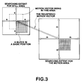
- Figure 3 shows a model by which the still and motion areas are described.
- a block in a basic position in the still search area and one in the motion search area are shown in Figure 3.
- the extents that the block can be shifted for searching in the horizontal and vertical directions in the still area are "S" as shown in Figure 3
- both of the extents that the block can be shifted for searching in the horizontal and vertical directions in the motion area are "m” as shown in Figure 3.
- two squared regions indicate positions of the upper left-hand corner pixels in the still and motion areas.
- the still area is spread around the position in which the subject block of the present frame is located, and the motion area is spread around the position shifted from the position of the subject block according to a registered motion vector.
- a memory 20 is arranged to receive the image data of a previous last frame output from the frame memory shown in Figure 1 via the line 104.
- a computing circuit 22 is arranged to receive the image data of the present frame via the line 102.
- the computing circuit 22 outputs a vector which indicates a position of an object block relative to the subject block via a line 201.
- the vector is supplied to a multiplexer (MPX) 23, and the MPX 23 produces address data in response to the vector.
- the address data are input to the memory 20 via a line 202, and the memory 20 reads the image data of the object block.
- the image data of the object block are supplied to the MPX 23 via a line 203, and the MPX supplies them to the computing circuit 22 via a line 204.
- the computing circuit 22 computes differences between the subject block and the object block by using a predetermined evaluating function. It is possible to use the function described in the prior art as the predetermined evaluating function.
- the computing circuit 22 updates the vector indicating the object block such that all blocks in the still search area are designated as the object block in turn.
- the blocks can be overlapped with each other and can be shifted by one pixel as a unit.
- the value of the differences and the vector indicating the object block are supplied to a comparison circuit 24 via a line 205, and the comparison circuit 24 updates a stored vector by the vector when the value of the differences is smaller than a stored value. Accordingly, the smallest value of the differences and the corresponding vector remain in the comparison circuit 24.
- a vector storing memory 21 registers motion vectors of the previous frame for all blocks.
- the computing circuit 22 reads a registered motion vector corresponding to the subject block, and updates the vector indicating the object block such that all blocks in the motion area are designated as the object block in turn.
- the computing circuit 22 supplies an ending signal which indicates an end of evaluating all blocks to a vector output circuit 25 via a line 206.
- the vector output circuit 25 reads out the vector remaining in the comparison circuit 24 as a motion vector of the subject block, and supplies an instruction signal to the MPX 23 via a line 207 for reading out the image signal of the block corresponding to the vector.
- the MPX 23 reads out the image signal of the most similar block to the subject block from the memory 20 via the line 203 and outputs it to the external line 105 via a line 208.
- the vector output circuit 25 outputs the motion vector on the external line 106 via a line 209. As described above, the motion vector on the line 106 is utilised for encoding the image signal.
- the motion vector is also supplied to an updating circuit 26 via a line 210.
- the updating circuit 26 discriminates whether the motion vector is raised in a motion region of the image or a still region of the image.
- the circuit 26 registers the motion vector in the vector storing memory 21 instead of the old motion vector of the block positioned at the same position in the previous frame if the motion vector is discriminated to be raised in the motion region.
- the motion vector is discriminated as an invalid vector for predicting if both ( ⁇ vx ⁇ ⁇ S/2 ) and ( ⁇ vy ⁇ ⁇ S/2 ) are true and is discriminated as a valid vector for predicting in other cases.
- a motion vector having a value within a predetermined range shown by a dotted line in Figure 3 is ignored by the predicting circuit.
- the previous motion vector is automatically kept in the memory 21 as the predictive vector. In other words, the predictive vector is interpolated by the previous predictive vector positioned at the same position in the previous frame.
- the apparatus shown in Figure 1 can detect dependable motion vectors, because the similar block in the previous frame to the subject block is searched in both the still search area and the motion search area in both of which there is a fair possibility of occurring the similar block to tee subject block. And, the apparatus shown in Figure 1 can make a dependable prediction of the motion vector, because the unreliable motion vectors are ignored for predicting the motion vectors.
- the present and previous images may be chosen to be fields or frames, according to the needs of the system designer.
- the previous image (field or frame) selected for use in the block matching search need not be the one immediately preceding the present image in the motion image sequence.
Applications Claiming Priority (2)
| Application Number | Priority Date | Filing Date | Title |
|---|---|---|---|
| JP26870992A JPH06209466A (ja) | 1992-10-07 | 1992-10-07 | 動ベクトル検出装置 |
| JP268709/92 | 1992-10-07 |
Publications (3)
| Publication Number | Publication Date |
|---|---|
| EP0592128A2 true EP0592128A2 (fr) | 1994-04-13 |
| EP0592128A3 EP0592128A3 (fr) | 1994-11-30 |
| EP0592128B1 EP0592128B1 (fr) | 1998-01-28 |
Family
ID=17462277
Family Applications (1)
| Application Number | Title | Priority Date | Filing Date |
|---|---|---|---|
| EP19930307572 Expired - Lifetime EP0592128B1 (fr) | 1992-10-07 | 1993-09-24 | Détection et prédiction de vecteurs de mouvement |
Country Status (4)
| Country | Link |
|---|---|
| US (1) | US5787205A (fr) |
| EP (1) | EP0592128B1 (fr) |
| JP (1) | JPH06209466A (fr) |
| DE (1) | DE69316696T2 (fr) |
Cited By (6)
| Publication number | Priority date | Publication date | Assignee | Title |
|---|---|---|---|---|
| WO1998014010A1 (fr) * | 1996-09-27 | 1998-04-02 | Nds Limited | Procede et appareil d'estimation du mouvement |
| US5790208A (en) * | 1995-12-12 | 1998-08-04 | Electronics And Telecommunications Research Intstitute | Apparatus for estimating frame-to-frame and field-to-field motions |
| US5946405A (en) * | 1995-12-23 | 1999-08-31 | Korea Telecommunication Authority | Block-matching motion estimation apparatus under use of linear systolic array architecture |
| WO2001045420A1 (fr) * | 1999-12-17 | 2001-06-21 | Koninklijke Philips Electronics N.V. | Estimation de transmission d'images video |
| WO2001099437A2 (fr) * | 2000-06-16 | 2001-12-27 | Intel Corporation | Procede permettant de realiser une estimation de mouvement |
| US7266151B2 (en) | 2002-09-04 | 2007-09-04 | Intel Corporation | Method and system for performing motion estimation using logarithmic search |
Families Citing this family (3)
| Publication number | Priority date | Publication date | Assignee | Title |
|---|---|---|---|---|
| JPH10336668A (ja) * | 1997-06-02 | 1998-12-18 | Sharp Corp | 動きベクトル検出装置 |
| US6643387B1 (en) * | 1999-01-28 | 2003-11-04 | Sarnoff Corporation | Apparatus and method for context-based indexing and retrieval of image sequences |
| JP4709794B2 (ja) * | 2007-03-15 | 2011-06-22 | 株式会社東芝 | 動き推定装置及びその方法 |
Citations (5)
| Publication number | Priority date | Publication date | Assignee | Title |
|---|---|---|---|---|
| EP0360698A1 (fr) * | 1988-09-23 | 1990-03-28 | THOMSON multimedia | Procédé et dispositif d'estimation de mouvement dans une séquence d'images animées |
| JPH02294180A (ja) * | 1989-05-08 | 1990-12-05 | Matsushita Electric Ind Co Ltd | 動き内挿装置 |
| JPH04127690A (ja) * | 1990-09-19 | 1992-04-28 | Hitachi Ltd | 動画像動きベクトル推定方式 |
| WO1992019068A1 (fr) * | 1991-04-12 | 1992-10-29 | Dv Sweden Ab | Procede d'estimation des parties a mouvement contenus dans des signaux video |
| EP0518314A2 (fr) * | 1991-06-12 | 1992-12-16 | Mitsubishi Denki Kabushiki Kaisha | Dispositif de prédiction compensée en mouvement |
Family Cites Families (9)
| Publication number | Priority date | Publication date | Assignee | Title |
|---|---|---|---|---|
| JPS58197984A (ja) * | 1982-05-14 | 1983-11-17 | Nec Corp | テレビジヨン信号の適応予測符号化装置 |
| US5162923A (en) * | 1988-02-22 | 1992-11-10 | Canon Kabushiki Kaisha | Method and apparatus for encoding frequency components of image information |
| FR2633137B1 (fr) * | 1988-06-21 | 1990-11-09 | Labo Electronique Physique | Systeme d'emission et reception de television a haute definition a estimateur de vitesses ameliore et a debit de donnees reduit |
| US5086487A (en) * | 1988-11-24 | 1992-02-04 | Canon Kabushiki Kaisha | Method and apparatus for image encoding in which reference pixels for predictive encoding can be selected based on image size |
| US5043808A (en) * | 1990-03-19 | 1991-08-27 | At&T Bell Laboratories | High definition television arrangement employing motion compensated prediction error signals |
| US5150209A (en) * | 1990-05-11 | 1992-09-22 | Picturetel Corporation | Hierarchical entropy coded lattice threshold quantization encoding method and apparatus for image and video compression |
| JP2892783B2 (ja) * | 1990-07-09 | 1999-05-17 | 松下電器産業株式会社 | 動画像信号の符号化装置 |
| JPH04334188A (ja) * | 1991-05-08 | 1992-11-20 | Nec Corp | 動画像信号の符号化方式 |
| US5210605A (en) * | 1991-06-11 | 1993-05-11 | Trustees Of Princeton University | Method and apparatus for determining motion vectors for image sequences |
-
1992
- 1992-10-07 JP JP26870992A patent/JPH06209466A/ja active Pending
-
1993
- 1993-09-24 DE DE1993616696 patent/DE69316696T2/de not_active Expired - Lifetime
- 1993-09-24 EP EP19930307572 patent/EP0592128B1/fr not_active Expired - Lifetime
-
1997
- 1997-09-18 US US08/933,501 patent/US5787205A/en not_active Expired - Lifetime
Patent Citations (5)
| Publication number | Priority date | Publication date | Assignee | Title |
|---|---|---|---|---|
| EP0360698A1 (fr) * | 1988-09-23 | 1990-03-28 | THOMSON multimedia | Procédé et dispositif d'estimation de mouvement dans une séquence d'images animées |
| JPH02294180A (ja) * | 1989-05-08 | 1990-12-05 | Matsushita Electric Ind Co Ltd | 動き内挿装置 |
| JPH04127690A (ja) * | 1990-09-19 | 1992-04-28 | Hitachi Ltd | 動画像動きベクトル推定方式 |
| WO1992019068A1 (fr) * | 1991-04-12 | 1992-10-29 | Dv Sweden Ab | Procede d'estimation des parties a mouvement contenus dans des signaux video |
| EP0518314A2 (fr) * | 1991-06-12 | 1992-12-16 | Mitsubishi Denki Kabushiki Kaisha | Dispositif de prédiction compensée en mouvement |
Non-Patent Citations (2)
| Title |
|---|
| PATENT ABSTRACTS OF JAPAN vol. 15, no. 74 (E-1036) 21 February 1991 & JP-A-02 294 180 (MATSUSHITA ELECTRIC IND. CO. LTD.) 5 December 1990 * |
| PATENT ABSTRACTS OF JAPAN vol. 16, no. 392 (E-1251) 20 August 1992 & JP-A-04 127 690 (HITACHI LTD.) 28 April 1992 * |
Cited By (7)
| Publication number | Priority date | Publication date | Assignee | Title |
|---|---|---|---|---|
| US5790208A (en) * | 1995-12-12 | 1998-08-04 | Electronics And Telecommunications Research Intstitute | Apparatus for estimating frame-to-frame and field-to-field motions |
| US5946405A (en) * | 1995-12-23 | 1999-08-31 | Korea Telecommunication Authority | Block-matching motion estimation apparatus under use of linear systolic array architecture |
| WO1998014010A1 (fr) * | 1996-09-27 | 1998-04-02 | Nds Limited | Procede et appareil d'estimation du mouvement |
| WO2001045420A1 (fr) * | 1999-12-17 | 2001-06-21 | Koninklijke Philips Electronics N.V. | Estimation de transmission d'images video |
| WO2001099437A2 (fr) * | 2000-06-16 | 2001-12-27 | Intel Corporation | Procede permettant de realiser une estimation de mouvement |
| WO2001099437A3 (fr) * | 2000-06-16 | 2002-08-08 | Intel Corp | Procede permettant de realiser une estimation de mouvement |
| US7266151B2 (en) | 2002-09-04 | 2007-09-04 | Intel Corporation | Method and system for performing motion estimation using logarithmic search |
Also Published As
| Publication number | Publication date |
|---|---|
| EP0592128A3 (fr) | 1994-11-30 |
| JPH06209466A (ja) | 1994-07-26 |
| EP0592128B1 (fr) | 1998-01-28 |
| US5787205A (en) | 1998-07-28 |
| DE69316696T2 (de) | 1998-06-18 |
| DE69316696D1 (de) | 1998-03-05 |
Similar Documents
| Publication | Publication Date | Title |
|---|---|---|
| CA1267721A (fr) | Appareil de codage efficace des signaux de television | |
| KR0148154B1 (ko) | 움직임크기에 따른 동영상데이타의 부호화방법 및 장치 | |
| EP0889651B1 (fr) | Codeur d'image et decodeur d'image | |
| US4951140A (en) | Image encoding apparatus | |
| EP0877530B1 (fr) | Procede de codage et de decodage d'images numeriques | |
| KR100803611B1 (ko) | 영상의 부호화, 복호화 방법 및 장치 | |
| US5592228A (en) | Video encoder using global motion estimation and polygonal patch motion estimation | |
| US5598215A (en) | Moving image encoder and decoder using contour extraction | |
| EP0679033A2 (fr) | Appareils de codage et de décodage avec quantification vectorielle | |
| US6418168B1 (en) | Motion vector detection apparatus, method of the same, and image processing apparatus | |
| EP0869682A1 (fr) | Méthodes de codage et décodage d'images animées, et les appareils de décodage et de codage respectifs | |
| WO2005088981A1 (fr) | Appareil de codage, procede de codage, appareil de decodage, procede de decodage | |
| KR19990015907A (ko) | 움직임 벡터 부호화 방법 및 그 장치 | |
| EP0592128B1 (fr) | Détection et prédiction de vecteurs de mouvement | |
| KR100646302B1 (ko) | 움직임 벡터 검출 장치 및 움직임 벡터 검출 방법 | |
| US6819715B2 (en) | Image decoding method, image decoding apparatus, and data storage medium | |
| EP0665692A2 (fr) | Méthode et appareil de collation d'images | |
| US7916788B2 (en) | Motion picture encoding method and device | |
| US8059719B2 (en) | Adaptive area of influence filter | |
| KR100238893B1 (ko) | 참조 움직임 벡터수에 기초한 움직임 벡터 부호화 방법 및 그 장치 | |
| US6611559B1 (en) | Apparatus and method of detecting motion vectors by calculating a correlation degree between each candidate block | |
| US7224842B2 (en) | Object recognition apparatus and object recognition method | |
| JPH08265764A (ja) | 映像信号符号化装置 | |
| EP0695096A1 (fr) | Dispositif pour détecter des vecteurs de mouvement et à coder des signals d'image | |
| JPH08294129A (ja) | 動きベクトル検出装置および検出方法 |
Legal Events
| Date | Code | Title | Description |
|---|---|---|---|
| PUAI | Public reference made under article 153(3) epc to a published international application that has entered the european phase |
Free format text: ORIGINAL CODE: 0009012 |
|
| AK | Designated contracting states |
Kind code of ref document: A2 Designated state(s): DE FR GB |
|
| PUAL | Search report despatched |
Free format text: ORIGINAL CODE: 0009013 |
|
| AK | Designated contracting states |
Kind code of ref document: A3 Designated state(s): DE FR GB |
|
| 17P | Request for examination filed |
Effective date: 19950421 |
|
| 17Q | First examination report despatched |
Effective date: 19960723 |
|
| GRAG | Despatch of communication of intention to grant |
Free format text: ORIGINAL CODE: EPIDOS AGRA |
|
| GRAG | Despatch of communication of intention to grant |
Free format text: ORIGINAL CODE: EPIDOS AGRA |
|
| GRAH | Despatch of communication of intention to grant a patent |
Free format text: ORIGINAL CODE: EPIDOS IGRA |
|
| GRAH | Despatch of communication of intention to grant a patent |
Free format text: ORIGINAL CODE: EPIDOS IGRA |
|
| GRAA | (expected) grant |
Free format text: ORIGINAL CODE: 0009210 |
|
| AK | Designated contracting states |
Kind code of ref document: B1 Designated state(s): DE FR GB |
|
| REF | Corresponds to: |
Ref document number: 69316696 Country of ref document: DE Date of ref document: 19980305 |
|
| ET | Fr: translation filed | ||
| PLBE | No opposition filed within time limit |
Free format text: ORIGINAL CODE: 0009261 |
|
| STAA | Information on the status of an ep patent application or granted ep patent |
Free format text: STATUS: NO OPPOSITION FILED WITHIN TIME LIMIT |
|
| 26N | No opposition filed | ||
| REG | Reference to a national code |
Ref country code: GB Ref legal event code: IF02 |
|
| PGFP | Annual fee paid to national office [announced via postgrant information from national office to epo] |
Ref country code: GB Payment date: 20110922 Year of fee payment: 19 Ref country code: DE Payment date: 20110930 Year of fee payment: 19 Ref country code: FR Payment date: 20111005 Year of fee payment: 19 |
|
| GBPC | Gb: european patent ceased through non-payment of renewal fee |
Effective date: 20120924 |
|
| REG | Reference to a national code |
Ref country code: FR Ref legal event code: ST Effective date: 20130531 |
|
| REG | Reference to a national code |
Ref country code: DE Ref legal event code: R119 Ref document number: 69316696 Country of ref document: DE Effective date: 20130403 |
|
| PG25 | Lapsed in a contracting state [announced via postgrant information from national office to epo] |
Ref country code: DE Free format text: LAPSE BECAUSE OF NON-PAYMENT OF DUE FEES Effective date: 20130403 Ref country code: GB Free format text: LAPSE BECAUSE OF NON-PAYMENT OF DUE FEES Effective date: 20120924 |
|
| PG25 | Lapsed in a contracting state [announced via postgrant information from national office to epo] |
Ref country code: FR Free format text: LAPSE BECAUSE OF NON-PAYMENT OF DUE FEES Effective date: 20121001 |