EP0330258B1 - Dispositif pour cambrer un outil d'une presse à plier - Google Patents
Dispositif pour cambrer un outil d'une presse à plier Download PDFInfo
- Publication number
- EP0330258B1 EP0330258B1 EP89200337A EP89200337A EP0330258B1 EP 0330258 B1 EP0330258 B1 EP 0330258B1 EP 89200337 A EP89200337 A EP 89200337A EP 89200337 A EP89200337 A EP 89200337A EP 0330258 B1 EP0330258 B1 EP 0330258B1
- Authority
- EP
- European Patent Office
- Prior art keywords
- adjusting
- tool
- wedges
- adjusting wedges
- lower beam
- Prior art date
- Legal status (The legal status is an assumption and is not a legal conclusion. Google has not performed a legal analysis and makes no representation as to the accuracy of the status listed.)
- Expired - Lifetime
Links
- 238000005452 bending Methods 0.000 title claims abstract description 22
- 230000007935 neutral effect Effects 0.000 claims abstract description 11
- 230000000295 complement effect Effects 0.000 claims abstract description 8
- 229910000906 Bronze Inorganic materials 0.000 claims description 3
- 229910000831 Steel Inorganic materials 0.000 claims description 3
- 239000010974 bronze Substances 0.000 claims description 3
- KUNSUQLRTQLHQQ-UHFFFAOYSA-N copper tin Chemical compound [Cu].[Sn] KUNSUQLRTQLHQQ-UHFFFAOYSA-N 0.000 claims description 3
- 239000010959 steel Substances 0.000 claims description 3
- 238000004519 manufacturing process Methods 0.000 description 5
- 239000000463 material Substances 0.000 description 3
- 230000000712 assembly Effects 0.000 description 2
- 238000000429 assembly Methods 0.000 description 2
- 230000005540 biological transmission Effects 0.000 description 2
- 230000003247 decreasing effect Effects 0.000 description 1
- 230000002349 favourable effect Effects 0.000 description 1
- 238000003754 machining Methods 0.000 description 1
Images


Classifications
-
- B—PERFORMING OPERATIONS; TRANSPORTING
- B21—MECHANICAL METAL-WORKING WITHOUT ESSENTIALLY REMOVING MATERIAL; PUNCHING METAL
- B21D—WORKING OR PROCESSING OF SHEET METAL OR METAL TUBES, RODS OR PROFILES WITHOUT ESSENTIALLY REMOVING MATERIAL; PUNCHING METAL
- B21D5/00—Bending sheet metal along straight lines, e.g. to form simple curves
- B21D5/02—Bending sheet metal along straight lines, e.g. to form simple curves on press brakes without making use of clamping means
- B21D5/0272—Deflection compensating means
Definitions
- the invention relates to apparatuses for cambering a tool of a bending apparatus according to the preamble of claim 1 and claim 2.
- Such apparatuses serve for adjusting a compensation for the deflection of the upper beam at high loads occurring in a bending apparatus.
- a known apparatus usually a high number of adjusting elements along the length of the tool are provided which only provide a local support of the tool (see DE-A-17 52 346). Further for adjusting a desired camber all adjusting elements have to be adjusted accurately. As moreover all adjusting elements have a different shape or design and must be made with a relatively high accuracy, the manufacturing costs of the known apparatus are high.
- EP-0 067 766 discloses an apparatus according to the preamble of claim 1 and claim 2.
- one of the adjusting wedges is moveable in a direction transverse to their longitudinal direction.
- actuating means for moving the movable adjusting wedges are required along the length of this wedge.
- the joining complementary surfaces of the wedges are shaped in a complicated manner.
- the invention aims to provide apparatuses of this type which are simple and can be made at relatively low cost.
- one adjusting wedge is mounted stationary and the other adjusting wedge is slidable.
- both adjusting wedges each consist of two or more adjusting wedge parts connected to each other, wherein the curved complementary surfaces of the subsequent adjusting wedge parts are staggered in vertical direction.
- the mechanical manufacturing of the adjusting wedges becomes simple if the adjusting wedges are made of a relatively soft steel, wherein the movable surfaces of the adjusting wedge(s) are provided with a bronze layer.
- the adjusting wedges are mounted on the lower beam and are received in a recess in the lower side of the tool table.
- Fig. 1 shows a bending apparatus 1 comprising a stationary lower beam 2, on which a tool table 3 is mounted. A die 4 is fixed on the tool table 3.
- the bending apparatus 1 further comprises an upper beam 5 movable up and down and driven by two cylinder piston assemblies 6.
- sensors 7 are mounted near the cylinder piston assemblies 6, only one of the sensors being shown in fig. 1.
- Said sensors 7 are supported by substantially C-shaped supports 8 fully free of the frame of the bending apparatus 1, so that a deformation of the web plates 9 (only one of which is shown in fig. 1) during exertion of high forces does not affect the sensors 7.
- the upper beam 5 carries a stamp 10 which cooperates with the die 4 for bending a material plate.
- the stamp 10 or the die 4 With an opposite bending-through is generally indicated as camber. With a correct adjustment of the camber, a straight bending line is obtained during the bending operation.
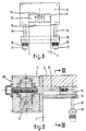
- the bending apparatus 1 For adjusting the camber the bending apparatus 1 is provided with a camber apparatus 11 comprising two adjusting wedges 12, 13 disposed upon eachother and further shown in figs. 2-5.
- the adjusting wedges 12, 13 are mounted on the lower beam 2, wherein a recess 14 is provided in the lower side of the tool table 3, in which recess the adjusting wedges 12, 13 are received.
- the tool table 3 is connected to the lower beam 2 under spring pressure, for which purpose in the shown embodiment three lateral rods 15 are mounted near the ends of the tool table 3 and in the centre of the lower beam 2, respectively, which lateral rods protrude outwardly of the lower beam 2 on both sides.
- Draw bolts 16 protrude through each lateral rod 15 on both sides of the lower beam 2, by means of which draw bolts 16 the tool table 3 is fixed, wherein Belleville- washers or cupped spring washers 18 are provided between each bolt head 17 and the lateral rods 15.
- the adjusting wedges 12, 13 are slidable with respect to eachother in longitudinal direction, in that at the embodiment shown the upper wedge 12 is slidable backward and forward, while the lower adjusting wedge 13 is attached to the lower beam 2.
- the actuation of the adjusting wedge 12 is provided through a draw/push bolt 19 which is movable backward and forward through a 90° transmission 20 by rotating a shaft 21 of the transmission 20.
- the shaft 21 can be rotated with a manually operable adjusting wheel or alteratively by means of an electromotor.
- the adjusting wedges 12, 13 are shown in a neutral position, wherein the upper surface 22 of the adjusting wedge 12 extends parallel to the lower surface of the adjusting wedge 13 and therefore no correction of the bending-through of the upper beam or the stamp 10, respectively, takes place.
- the upper surface 22 should be provided with a bending-through opposite to the bending-through of the upper beam 5, which opposite bending-through can be indicated as camber curve.
- the adjusting wedge has been moved maximum to the left, whereby the upper surface 22 has the maximum opposite bending-through, which is indicated strongly exaggerated in fig. 5 by a dashed line 24 with respect to a straight line 25.
- the maximum bending-through for a length of the adjusting wedges of 3 m is approximately 1 mm.
- the desired bending-through of the upper surface 22 of the adjusting wedge 12 for compensating the bending-through of the upper beam 5 is obtained in that the joining complementary surfaces 26, 27 in the side view of figs. 4 and 5 has a somewhat S-shaped curved trend, wherein the highest point 28 and the lowest point 29 of the curved surfaces 26, 27 in the neutral position of fig. 4 lies substantially at the location of the respective sensors 7.
- the trend of the curved surfaces 26, 27 substantially corresponds with the integral of the camber curve 24 shown in fig. 5.
- both adjusting wedges 12, 13 can for example consist of two interconnected adjusting wedge parts 30, 31 and 32, 33, respectively, wherein the curved complementary surfaces 26, 27 of the subsequent adjusting wedge parts 30, 31 and 32, 33, respectively, are staggered in vertical direction as shown in figs. 6, 7.
- the described camber apparatus 11 shows the advantage that the adjusting wedges 12, 13 extend along the whole length of the die 4 to be cambered, so that the support of the tool table 3 and thereby of the die 4 is provided along substantially the whole length.
- the operation of the camber apparatus 11 is very simple. Further the manufacturing of the adjusting wedges 12, 13 is not very complicated so that the manufacturing costs are relatively low.
- camber apparatus is mounted on the lower beam, it is of course also possible to incorporate the camber apparatus in the upper beam. Further only the lower adjusting wedge 13 or both adjusting wedges 12, 13 could be movable instead of the upper adjusting wedge 12.
- the adjusting wedges 12, 13 are made of relatively soft steel, whereby the mechanical machining of the curved surfaces 26, 27 is relatively simple.
- the surfaces 22 and 26 of the movable adjusting wedge 12 are provided with a layer of bronze.
Landscapes
- Engineering & Computer Science (AREA)
- Mechanical Engineering (AREA)
- Bending Of Plates, Rods, And Pipes (AREA)
- Shaping Of Tube Ends By Bending Or Straightening (AREA)
Claims (9)
Priority Applications (1)
| Application Number | Priority Date | Filing Date | Title |
|---|---|---|---|
| AT89200337T ATE63070T1 (de) | 1988-02-24 | 1989-02-10 | Vorrichtung zum woelben eines biegepresswerkzeuges. |
Applications Claiming Priority (2)
| Application Number | Priority Date | Filing Date | Title |
|---|---|---|---|
| NL8800462A NL8800462A (nl) | 1988-02-24 | 1988-02-24 | Inrichting voor het bomberen van een werktuig van een buiginrichting. |
| NL8800462 | 1988-02-24 |
Publications (2)
| Publication Number | Publication Date |
|---|---|
| EP0330258A1 EP0330258A1 (fr) | 1989-08-30 |
| EP0330258B1 true EP0330258B1 (fr) | 1991-05-02 |
Family
ID=19851842
Family Applications (1)
| Application Number | Title | Priority Date | Filing Date |
|---|---|---|---|
| EP89200337A Expired - Lifetime EP0330258B1 (fr) | 1988-02-24 | 1989-02-10 | Dispositif pour cambrer un outil d'une presse à plier |
Country Status (6)
| Country | Link |
|---|---|
| EP (1) | EP0330258B1 (fr) |
| AT (1) | ATE63070T1 (fr) |
| DE (1) | DE68900067D1 (fr) |
| ES (1) | ES2022745B3 (fr) |
| GR (1) | GR3001930T3 (fr) |
| NL (1) | NL8800462A (fr) |
Families Citing this family (6)
| Publication number | Priority date | Publication date | Assignee | Title |
|---|---|---|---|---|
| NL8901560A (nl) * | 1989-06-21 | 1991-01-16 | Wila Maschf Bv | Kantpers en een automatische bombeerinrichting daarvoor. |
| CH680772A5 (fr) * | 1989-09-11 | 1992-11-13 | Beyeler Machines Sa | |
| US6290401B1 (en) * | 1999-04-26 | 2001-09-18 | Corning Incorporated | Automated chip/phaser holder |
| FR2804048B1 (fr) * | 2000-01-21 | 2002-05-03 | Amada Europ Sa | Dispositif de reglage en hauteur d'une pluralite de porte-outils pour presse plieuse |
| US6725702B2 (en) | 2001-10-26 | 2004-04-27 | Ariel Financing Ltd. | Apparatus and method for overcoming angular deviations in a workpiece |
| WO2003039777A1 (fr) * | 2001-11-09 | 2003-05-15 | Ariel Financing Ltd. | Appareil et procede permettant de vaincre des deviations angulaires dans une piece a travailler |
Family Cites Families (6)
| Publication number | Priority date | Publication date | Assignee | Title |
|---|---|---|---|---|
| FR783147A (fr) * | 1934-03-05 | 1935-07-08 | Weingarten Vorm Hch Schatz Ag | Plieuse-cintreuse |
| DE1452677A1 (de) * | 1964-01-16 | 1969-04-24 | Robert Heitmann | Vorrichtung zum Ausgleich der Durchbiegung bei Pressen,insbesondere Abkantpressen |
| DE1752346C3 (de) * | 1968-05-11 | 1974-09-12 | Scharringhausen Maschinenbau Gmbh, 7526 Rheinsheim | Bombiervorrichtung für eine Abkantpresse |
| DE2534664A1 (de) * | 1975-08-02 | 1977-02-10 | Fastenrath Fasti Werk | Vorrichtung zum konvexen durchbiegen von werkzeugschienen an abkantpressen oder schwenkbiegemaschinen |
| DE2914744A1 (de) * | 1979-04-11 | 1980-10-30 | Weinbrenner Paul Maschbau | Bombiereinrichtung fuer eine abkantpresse o.dgl. |
| FR2507507B1 (fr) * | 1981-06-16 | 1986-07-04 | Promecan Sisson Lehmann | Dispositif de bombage d'un porte-outil d'une presse plieuse ou analogue |
-
1988
- 1988-02-24 NL NL8800462A patent/NL8800462A/nl not_active Application Discontinuation
-
1989
- 1989-02-10 EP EP89200337A patent/EP0330258B1/fr not_active Expired - Lifetime
- 1989-02-10 AT AT89200337T patent/ATE63070T1/de not_active IP Right Cessation
- 1989-02-10 ES ES89200337T patent/ES2022745B3/es not_active Expired - Lifetime
- 1989-02-10 DE DE8989200337T patent/DE68900067D1/de not_active Expired - Lifetime
-
1991
- 1991-05-10 GR GR91400594T patent/GR3001930T3/el unknown
Also Published As
| Publication number | Publication date |
|---|---|
| GR3001930T3 (en) | 1992-11-23 |
| ES2022745B3 (es) | 1991-12-01 |
| DE68900067D1 (de) | 1991-06-06 |
| EP0330258A1 (fr) | 1989-08-30 |
| NL8800462A (nl) | 1989-09-18 |
| ATE63070T1 (de) | 1991-05-15 |
Similar Documents
| Publication | Publication Date | Title |
|---|---|---|
| EP0387884B1 (fr) | Machine d'estampage et de formage pourvue de genouillères pour le mouvement alternatif des outils | |
| EP0404269B1 (fr) | Presse et dispositif de formage automatique de courbes | |
| JPH0688079B2 (ja) | プレスブレーキにおけるクラウニング装置 | |
| US4586361A (en) | Press brake deflection compensation structure | |
| US4783984A (en) | Apparatus for folding a sheet metal element | |
| EP0330258B1 (fr) | Dispositif pour cambrer un outil d'une presse à plier | |
| CN109906123A (zh) | 一种用于在金属板中形成波纹的折弯机以及使用这种折弯机的方法 | |
| EP0629496B1 (fr) | Presse à jeu d'outils pour le compactage de poudre | |
| US5622075A (en) | Bending machine | |
| CN115355814B (zh) | 一种钢板弹簧平面度检测设备 | |
| EP0116046B1 (fr) | Presse hydraulique | |
| KR890003805B1 (ko) | 프레스 브레이크 | |
| CA2014368C (fr) | Injecteur coulissant de pieces sur matrice d'estampage | |
| US5086639A (en) | Arrangement for carrying out pressing in eccentric presses | |
| US4977770A (en) | Automatable bending machine having crenelated rolls | |
| US3380284A (en) | Deforming device for elongated elements | |
| EP1074319B1 (fr) | Dispositif pour le pressage d'une plaque dans une forme désiré | |
| US3406549A (en) | Straightening machine | |
| US5060566A (en) | Press apparatus | |
| US6401513B1 (en) | Press brake with control wear linkages | |
| RU211134U1 (ru) | Устройство для гибки стержневых заготовок | |
| CN220611965U (zh) | 一种深度可调的冲孔模具 | |
| JPS59101236A (ja) | 薄板の縁部分を曲げる方法およびそのための工具 | |
| KR820000133Y1 (ko) | 프레스 브레이크의 소재 휨의 교정 장치 | |
| JP4601841B2 (ja) | プレスブレーキ |
Legal Events
| Date | Code | Title | Description |
|---|---|---|---|
| PUAI | Public reference made under article 153(3) epc to a published international application that has entered the european phase |
Free format text: ORIGINAL CODE: 0009012 |
|
| AK | Designated contracting states |
Kind code of ref document: A1 Designated state(s): AT BE CH DE ES FR GB GR IT LI NL SE |
|
| 17P | Request for examination filed |
Effective date: 19891129 |
|
| 17Q | First examination report despatched |
Effective date: 19900105 |
|
| GRAA | (expected) grant |
Free format text: ORIGINAL CODE: 0009210 |
|
| AK | Designated contracting states |
Kind code of ref document: B1 Designated state(s): AT BE CH DE ES FR GB GR IT LI NL SE |
|
| REF | Corresponds to: |
Ref document number: 63070 Country of ref document: AT Date of ref document: 19910515 Kind code of ref document: T |
|
| ITF | It: translation for a ep patent filed | ||
| REF | Corresponds to: |
Ref document number: 68900067 Country of ref document: DE Date of ref document: 19910606 |
|
| ET | Fr: translation filed | ||
| PLBE | No opposition filed within time limit |
Free format text: ORIGINAL CODE: 0009261 |
|
| STAA | Information on the status of an ep patent application or granted ep patent |
Free format text: STATUS: NO OPPOSITION FILED WITHIN TIME LIMIT |
|
| 26N | No opposition filed | ||
| REG | Reference to a national code |
Ref country code: GR Ref legal event code: FG4A Free format text: 3001930 |
|
| PGFP | Annual fee paid to national office [announced via postgrant information from national office to epo] |
Ref country code: GR Payment date: 19930225 Year of fee payment: 5 |
|
| PG25 | Lapsed in a contracting state [announced via postgrant information from national office to epo] |
Ref country code: GR Free format text: THE PATENT HAS BEEN ANNULLED BY A DECISION OF A NATIONAL AUTHORITY Effective date: 19940831 |
|
| REG | Reference to a national code |
Ref country code: GR Ref legal event code: MM2A Free format text: 3001930 |
|
| EAL | Se: european patent in force in sweden |
Ref document number: 89200337.7 |
|
| PGFP | Annual fee paid to national office [announced via postgrant information from national office to epo] |
Ref country code: CH Payment date: 20010302 Year of fee payment: 13 |
|
| REG | Reference to a national code |
Ref country code: GB Ref legal event code: IF02 |
|
| PG25 | Lapsed in a contracting state [announced via postgrant information from national office to epo] |
Ref country code: LI Free format text: LAPSE BECAUSE OF NON-PAYMENT OF DUE FEES Effective date: 20020228 Ref country code: CH Free format text: LAPSE BECAUSE OF NON-PAYMENT OF DUE FEES Effective date: 20020228 |
|
| REG | Reference to a national code |
Ref country code: CH Ref legal event code: PL |
|
| PGFP | Annual fee paid to national office [announced via postgrant information from national office to epo] |
Ref country code: FR Payment date: 20030123 Year of fee payment: 15 |
|
| PGFP | Annual fee paid to national office [announced via postgrant information from national office to epo] |
Ref country code: DE Payment date: 20030124 Year of fee payment: 15 |
|
| PGFP | Annual fee paid to national office [announced via postgrant information from national office to epo] |
Ref country code: ES Payment date: 20030127 Year of fee payment: 15 |
|
| PGFP | Annual fee paid to national office [announced via postgrant information from national office to epo] |
Ref country code: BE Payment date: 20030204 Year of fee payment: 15 |
|
| PGFP | Annual fee paid to national office [announced via postgrant information from national office to epo] |
Ref country code: GB Payment date: 20030205 Year of fee payment: 15 |
|
| PGFP | Annual fee paid to national office [announced via postgrant information from national office to epo] |
Ref country code: SE Payment date: 20030217 Year of fee payment: 15 |
|
| PGFP | Annual fee paid to national office [announced via postgrant information from national office to epo] |
Ref country code: AT Payment date: 20030227 Year of fee payment: 15 |
|
| PGFP | Annual fee paid to national office [announced via postgrant information from national office to epo] |
Ref country code: NL Payment date: 20030228 Year of fee payment: 15 |
|
| PG25 | Lapsed in a contracting state [announced via postgrant information from national office to epo] |
Ref country code: GB Free format text: LAPSE BECAUSE OF NON-PAYMENT OF DUE FEES Effective date: 20040210 Ref country code: AT Free format text: LAPSE BECAUSE OF NON-PAYMENT OF DUE FEES Effective date: 20040210 |
|
| PG25 | Lapsed in a contracting state [announced via postgrant information from national office to epo] |
Ref country code: SE Free format text: LAPSE BECAUSE OF NON-PAYMENT OF DUE FEES Effective date: 20040211 Ref country code: ES Free format text: LAPSE BECAUSE OF NON-PAYMENT OF DUE FEES Effective date: 20040211 |
|
| PG25 | Lapsed in a contracting state [announced via postgrant information from national office to epo] |
Ref country code: BE Free format text: LAPSE BECAUSE OF NON-PAYMENT OF DUE FEES Effective date: 20040228 |
|
| BERE | Be: lapsed |
Owner name: *LIET CORNELIS HENDRICUS Effective date: 20040228 |
|
| PG25 | Lapsed in a contracting state [announced via postgrant information from national office to epo] |
Ref country code: NL Free format text: LAPSE BECAUSE OF NON-PAYMENT OF DUE FEES Effective date: 20040901 Ref country code: DE Free format text: LAPSE BECAUSE OF NON-PAYMENT OF DUE FEES Effective date: 20040901 |
|
| EUG | Se: european patent has lapsed | ||
| GBPC | Gb: european patent ceased through non-payment of renewal fee |
Effective date: 20040210 |
|
| PG25 | Lapsed in a contracting state [announced via postgrant information from national office to epo] |
Ref country code: FR Free format text: LAPSE BECAUSE OF NON-PAYMENT OF DUE FEES Effective date: 20041029 |
|
| NLV4 | Nl: lapsed or anulled due to non-payment of the annual fee |
Effective date: 20040901 |
|
| REG | Reference to a national code |
Ref country code: FR Ref legal event code: ST |
|
| PG25 | Lapsed in a contracting state [announced via postgrant information from national office to epo] |
Ref country code: IT Free format text: LAPSE BECAUSE OF NON-PAYMENT OF DUE FEES;WARNING: LAPSES OF ITALIAN PATENTS WITH EFFECTIVE DATE BEFORE 2007 MAY HAVE OCCURRED AT ANY TIME BEFORE 2007. THE CORRECT EFFECTIVE DATE MAY BE DIFFERENT FROM THE ONE RECORDED. Effective date: 20050210 |
|
| REG | Reference to a national code |
Ref country code: ES Ref legal event code: FD2A Effective date: 20040211 |