EP0330042B1 - Support d'enregistrement - Google Patents
Support d'enregistrement Download PDFInfo
- Publication number
- EP0330042B1 EP0330042B1 EP89102432A EP89102432A EP0330042B1 EP 0330042 B1 EP0330042 B1 EP 0330042B1 EP 89102432 A EP89102432 A EP 89102432A EP 89102432 A EP89102432 A EP 89102432A EP 0330042 B1 EP0330042 B1 EP 0330042B1
- Authority
- EP
- European Patent Office
- Prior art keywords
- intermediate sheet
- sheets
- sheet arrangement
- arrangement
- carrier according
- Prior art date
- Legal status (The legal status is an assumption and is not a legal conclusion. Google has not performed a legal analysis and makes no representation as to the accuracy of the status listed.)
- Expired - Lifetime
Links
- 239000000853 adhesive Substances 0.000 claims abstract description 38
- 230000001070 adhesive effect Effects 0.000 claims abstract description 38
- 239000012790 adhesive layer Substances 0.000 claims description 18
- OKTJSMMVPCPJKN-UHFFFAOYSA-N Carbon Chemical compound [C] OKTJSMMVPCPJKN-UHFFFAOYSA-N 0.000 claims description 6
- 229910052799 carbon Inorganic materials 0.000 claims description 6
- 239000010410 layer Substances 0.000 claims description 5
- 238000000605 extraction Methods 0.000 claims description 4
- 229920001296 polysiloxane Polymers 0.000 claims 1
- 238000009877 rendering Methods 0.000 claims 1
- 238000011144 upstream manufacturing Methods 0.000 claims 1
- 230000000694 effects Effects 0.000 abstract description 4
- 150000001875 compounds Chemical class 0.000 abstract description 2
- 230000002411 adverse Effects 0.000 abstract 1
- 238000003763 carbonization Methods 0.000 description 5
- 238000000926 separation method Methods 0.000 description 5
- 230000006870 function Effects 0.000 description 4
- 238000004519 manufacturing process Methods 0.000 description 4
- 230000008859 change Effects 0.000 description 3
- 238000002372 labelling Methods 0.000 description 3
- 230000004913 activation Effects 0.000 description 2
- 239000000969 carrier Substances 0.000 description 2
- 230000009471 action Effects 0.000 description 1
- 230000003213 activating effect Effects 0.000 description 1
- 238000004026 adhesive bonding Methods 0.000 description 1
- 238000013459 approach Methods 0.000 description 1
- 230000000903 blocking effect Effects 0.000 description 1
- 239000011248 coating agent Substances 0.000 description 1
- 238000000576 coating method Methods 0.000 description 1
- 238000012937 correction Methods 0.000 description 1
- 238000013461 design Methods 0.000 description 1
- 230000001066 destructive effect Effects 0.000 description 1
- 238000004090 dissolution Methods 0.000 description 1
- 239000003292 glue Substances 0.000 description 1
- 230000001771 impaired effect Effects 0.000 description 1
- 239000000463 material Substances 0.000 description 1
- 238000000034 method Methods 0.000 description 1
- 210000001747 pupil Anatomy 0.000 description 1
- 230000002787 reinforcement Effects 0.000 description 1
- 230000003014 reinforcing effect Effects 0.000 description 1
- 239000012488 sample solution Substances 0.000 description 1
- 230000008719 thickening Effects 0.000 description 1
- 238000012549 training Methods 0.000 description 1
- 238000012546 transfer Methods 0.000 description 1
Images



Classifications
-
- G—PHYSICS
- G11—INFORMATION STORAGE
- G11B—INFORMATION STORAGE BASED ON RELATIVE MOVEMENT BETWEEN RECORD CARRIER AND TRANSDUCER
- G11B5/00—Recording by magnetisation or demagnetisation of a record carrier; Reproducing by magnetic means; Record carriers therefor
- G11B5/74—Record carriers characterised by the form, e.g. sheet shaped to wrap around a drum
-
- B—PERFORMING OPERATIONS; TRANSPORTING
- B41—PRINTING; LINING MACHINES; TYPEWRITERS; STAMPS
- B41L—APPARATUS OR DEVICES FOR MANIFOLDING, DUPLICATING OR PRINTING FOR OFFICE OR OTHER COMMERCIAL PURPOSES; ADDRESSING MACHINES OR LIKE SERIES-PRINTING MACHINES
- B41L1/00—Devices for performing operations in connection with manifolding by means of pressure-sensitive layers or intermediaries, e.g. carbons; Accessories for manifolding purposes
- B41L1/20—Manifolding assemblies, e.g. book-like assemblies
- B41L1/22—Manifolding assemblies, e.g. book-like assemblies made up of single sheets or forms
-
- B—PERFORMING OPERATIONS; TRANSPORTING
- B41—PRINTING; LINING MACHINES; TYPEWRITERS; STAMPS
- B41M—PRINTING, DUPLICATING, MARKING, OR COPYING PROCESSES; COLOUR PRINTING
- B41M5/00—Duplicating or marking methods; Sheet materials for use therein
- B41M5/10—Duplicating or marking methods; Sheet materials for use therein by using carbon paper or the like
-
- G—PHYSICS
- G09—EDUCATION; CRYPTOGRAPHY; DISPLAY; ADVERTISING; SEALS
- G09B—EDUCATIONAL OR DEMONSTRATION APPLIANCES; APPLIANCES FOR TEACHING, OR COMMUNICATING WITH, THE BLIND, DEAF OR MUTE; MODELS; PLANETARIA; GLOBES; MAPS; DIAGRAMS
- G09B3/00—Manually or mechanically operated teaching appliances working with questions and answers
- G09B3/02—Manually or mechanically operated teaching appliances working with questions and answers of the type wherein the student is expected to construct an answer to the question which is presented or wherein the machine gives an answer to the question presented by a student
- G09B3/04—Manually or mechanically operated teaching appliances working with questions and answers of the type wherein the student is expected to construct an answer to the question which is presented or wherein the machine gives an answer to the question presented by a student of chart form
-
- Y—GENERAL TAGGING OF NEW TECHNOLOGICAL DEVELOPMENTS; GENERAL TAGGING OF CROSS-SECTIONAL TECHNOLOGIES SPANNING OVER SEVERAL SECTIONS OF THE IPC; TECHNICAL SUBJECTS COVERED BY FORMER USPC CROSS-REFERENCE ART COLLECTIONS [XRACs] AND DIGESTS
- Y10—TECHNICAL SUBJECTS COVERED BY FORMER USPC
- Y10S—TECHNICAL SUBJECTS COVERED BY FORMER USPC CROSS-REFERENCE ART COLLECTIONS [XRACs] AND DIGESTS
- Y10S428/00—Stock material or miscellaneous articles
- Y10S428/916—Fraud or tamper detecting
-
- Y—GENERAL TAGGING OF NEW TECHNOLOGICAL DEVELOPMENTS; GENERAL TAGGING OF CROSS-SECTIONAL TECHNOLOGIES SPANNING OVER SEVERAL SECTIONS OF THE IPC; TECHNICAL SUBJECTS COVERED BY FORMER USPC CROSS-REFERENCE ART COLLECTIONS [XRACs] AND DIGESTS
- Y10—TECHNICAL SUBJECTS COVERED BY FORMER USPC
- Y10S—TECHNICAL SUBJECTS COVERED BY FORMER USPC CROSS-REFERENCE ART COLLECTIONS [XRACs] AND DIGESTS
- Y10S462/00—Books, strips, and leaves for manifolding
- Y10S462/90—Adhesive
- Y10S462/901—Pressure sensitive
-
- Y—GENERAL TAGGING OF NEW TECHNOLOGICAL DEVELOPMENTS; GENERAL TAGGING OF CROSS-SECTIONAL TECHNOLOGIES SPANNING OVER SEVERAL SECTIONS OF THE IPC; TECHNICAL SUBJECTS COVERED BY FORMER USPC CROSS-REFERENCE ART COLLECTIONS [XRACs] AND DIGESTS
- Y10—TECHNICAL SUBJECTS COVERED BY FORMER USPC
- Y10T—TECHNICAL SUBJECTS COVERED BY FORMER US CLASSIFICATION
- Y10T428/00—Stock material or miscellaneous articles
- Y10T428/14—Layer or component removable to expose adhesive
Definitions
- the present invention relates to a record carrier according to the preamble of claim 1.
- CH-PS-611 061 (DE-A-25 31 331) has disclosed task sheets with two sheets joined together along three edge edges. In between there is an intermediate sheet, a carbon paper, which can be pulled out in the fourth edge region of the connected sheets.
- the correct solution of a given task is printed on one of the sheet sides opposite one another on the intermediate sheet, not recognizable from the outside when the intermediate sheet is inserted.
- a pupil solves the given task in a specially designed solution field, whereby his recording is copied onto the page of the sheet printed with the correct solution. Then the student removes the interleaf, which on the one hand shows the correct solution through the clear, clearly designed sheet, but on the other hand makes it impossible to correct his already entered solution as follows:
- a reinsertion of the intermediate sheet causing the recording contrast, here the carbon paper, is made impossible by the fact that the latter is folded around the edge of one of the sheets at the pull-out opening and is held in this position by a deflecting fold. It can only be pulled out around the edge of one of these sheets. A It is impossible to reinsert the intermediate sheet under the deflection fold and around the edge of the one sheet.
- This deflection fold is relatively complex to manufacture.
- precautions must be taken at the edge of one of the sheets around which the intermediate sheet is pulled out, which prevent this edge from being torn out when the intermediate sheet is pulled out.
- the provision of the deflection folds, together with a reinforcement of the edge mentioned, results in an undesirable local thickening of the record carrier, which is disadvantageous in particular when binding a multiplicity of such carriers to form a book.
- the adhesive area is provided on at least one of the two opposite sides of the sheets connected one above the other in such a way that, after removal of the intermediate sheet arrangement, the difficult-to-detachable connection of these two sheets is created, making it impossible to reinsert the intermediate sheet arrangement necessary for generating the recording contrast. This ensures that a previously made recording cannot be supplemented, corrected etc. after removing the interleaving arrangement.
- the recording contrast is pressed through the recording pressure, such as by means of a ballpoint pen, onto one of the sheets from the intermediate sheet arrangement which here brings about the recording contrast onto the other of the sheets.
- the present invention based on a record carrier of the latter type, aims to remedy its disadvantages.
- the record carrier of the above-mentioned type is distinguished by the characterizing part of claim 1.
- the active connection which brings about the recording contrast in an area of the other intermediate chamber, which area at least partially overlaps the adhesive layer area, means that the recording contrast is generated by the intended one Detention area can no longer be impaired by separating the intermediate chamber essential for the recording contrast from that with the adhesive layer. In this way, the adhesive area can be produced in the production regardless of the recordings to be made later.
- the above-mentioned problem is therefore solved by preventing a relevant recording contrast from being applied to the above-mentioned sheet of the other intermediate chamber from the outside. After removal of the interleaving arrangement, only the recording contrast generated by the active compound remains and, clearly, can then no longer be falsified.
- a preferred combination of information provided in advance and blocking the reinsertion of the intermediate sheet arrangement results from the wording of claim 5.
- the function of the pull-out element mentioned is preferably transferred to a sheet provided on the intermediate sheet arrangement, which brings about contrast, preferably carbon paper.
- the intermediate sheet arrangement then lies between the sheets connected one above the other at three edges. On the one hand, it is connected to one of the leaves at the fourth edge, extends through the leaves, merges at the area opposite the fourth edge into a contrast-producing leaf which, back, extends to the open edge where it is gripped can and can be pulled out with the entire interleaving arrangement, the procedure being preferably as claimed in claim 16.
- a sheet for distance learning, exams etc. can be realized, on which a student can only read the task, if necessary also on the sheet, then can solve it and after removing the interleaving arrangement the sample solution of the same completed task, but without changing his records on the sheet afterwards.
- the separation according to the invention on the one hand from the active contrast effecting recording contrast in the other intermediate chamber, on the other hand from the provided adhesive area in the one intermediate chamber, in order to connect the two sheets connected one above the other in a practically non-detachable manner after removal of the intermediate sheet arrangement, makes it possible for the intended adhesive area to be independent of recording areas to be provided.
- this adhesive area can be continuously applied to one of the sheets lying one above the other, it is further proposed according to claim 15 that this adhesive area provided also for connecting the two or at most the three connected one above the other Insert sheets by stacking them connected sheets, with the exception of the pocket for the intermediate sheet arrangement, are connected to this adhesive area: one of the sheets is coated completely or in strips with adhesive and the other, to be connected, is permanently bonded to the coated sheet in the marginal zones after inserting the intermediate sheet arrangement.
- a recording medium comprises two sheets, an upper sheet 1 and a lower sheet 3. These two sheets, as shown at 4, are connected one above the other to form a pocket, as glued together at the edges. Between the two sheets 1 and 3 there is an intermediate sheet arrangement 5.
- the intermediate sheet arrangement 5 separates the pocket formed by the two sheets 1 and 3 into two areas 7 and 9.
- the sheet 1 in an operative connection, such that during a recording operation, as shown with a ballpoint pen 11, according to FIG. 1, a recording contrast 13 on the intermediate sheet arrangement 5 or, as shown in FIG. 2, a Recording contrast 13 is applied to the side of the sheet 1 facing the intermediate sheet arrangement 5.
- the recording contrast 13 is applied to the intermediate sheet arrangement 5 according to FIG. 1, for example, in that the side of the upper sheet 1 facing this arrangement 5, as shown schematically at 15, is carbonized in such a way that, due to the recording pressure, as caused by the ballpoint pen 11 , the recording contrast in the form of carbonization 13 is pressed onto the intermediate sheet arrangement 5.
- the recording contrast as shown in FIG. 2, is to be adopted on sheet 1
- the side of the intermediate sheet arrangement 5 facing this sheet 1 is carbonized, for example.
- the second intermediate chamber 9, clearly separated from the first, 7 by the intermediate sheet arrangement 5, has an adhesive area 17, as shown, preferably continuously continuous or strip-shaped along the sheet 3 as an adhesive area.
- the adhesive area 17 adheres well to the side of the sheet 3 facing the intermediate sheet arrangement 5, but not to the intermediate sheet arrangement 5, for which purpose at least the corresponding side 5a is designed, according to the selected adhesive with which the layer 17 is formed, is preferably siliconized for this purpose.
- the intermediate sheet arrangement 5 after applying a record removed, in this embodiment the recording contrast 13 remains on the interleaf arrangement and can then be perceived on the latter as read.
- the adhesive layer 17 now also comes into contact with the top sheet 1, with which the two sheets 1 and 3 are bonded in a non-destructive manner, which is practically impossible to remove.
- the recording contrast on the extended intermediate sheet arrangement 5 can be read or recognized in the embodiment variant according to FIG. 1 after the intermediate sheet arrangement 5 has been pulled out, it remains practically non-destructively in the embodiment variant according to FIG. 2 after the intermediate sheet arrangement 5 has been pulled out non-releasably glued sheets 1, 3, ie actually, and as entered there at 13, on sheet 1.
- the adhesive bonding of the two sheets 1 and 3 is intended in any case to ensure that a subsequent recording is readily recognizable as such after the intermediate sheet arrangement 5 has been removed.
- the above-mentioned operative connection in the intermediate chamber 7 is no longer effective for effecting the recording contrast transfer after the intermediate sheet arrangement 5 has been pulled out.
- the recorded contrast 13 in the exemplary embodiment according to FIG. 1 remains on the extended intermediate sheet arrangement and is readily recognizable as such there, because a recording contrast, for example caused by carbonization, on the intermediate sheet arrangement 5 can very well be obtained from a subsequent use of a conventional writing utensil recordings made can be distinguished.
- this embodiment variant enables immediate, clear recognition of the recording contrast on the extended intermediate sheet arrangement 5, since it is separated locally, precisely by this extension, from a recording contrast 19 which is subsequently applied to the sheet 1 from the outside, as with the ballpoint pen 11.
- the recording contrast 13 remains on the sheet 1, which, after the intermediate sheet arrangement 5 has been pulled out, is adhesively bonded to the sheet 3.
- a subsequent change of the recording contrast 13 is thus no longer possible, because after the intermediate sheet arrangement 5 has been removed, the aforementioned operative connection for generating the recording contrast is removed.
- This problem is preferably remedied here in that a color is chosen as the recording contrast 13, and thus for the carbonization 15 on the intermediate sheet arrangement 5, which color differs from the recording color of conventional writing utensils, for example red or green.
- the attachment of the adhesive area 17 is completely independent of where a recording is to be made on the record carrier.
- the bottom sheet 3 is continuously provided with the area 17 in its longitudinal dimension x, even in the transverse dimension entirely or in strips.
- an optimal use of material and space is achieved by designing the recording medium as a double recording medium.
- an outer sheet 1 is glued to both sides of the sheet 3, which now acts as the middle sheet, and an intermediate sheet arrangement 5 is provided on each side of the middle sheet 3.
- the middle sheet 3 is now coated to form both adhesive areas 17, preferably on both sides continuously in the longitudinal direction, in the transverse direction entirely or in strips, with the adhesive layer 17.
- FIG. 3 shows, in perspective, the recording medium according to the invention, the two or three sheets 1 and 3 being glued along three edge regions 4 and one or two intermediate sheet arrangements 5 being arranged between them.
- FIG. 4 shows, in supervision, a recording medium according to the invention, constructed as shown in FIG. 2 in cross section, as a single or double recording medium.
- the record carrier shown here is designed as a solution sheet for tasks, such as for teaching. 4a, the intermediate sheet arrangement 5 lies between the sheets 1 and 3 connected one above the other. These are glued to one another along the edge portions 4, the adhesive layer 17 continuous in the longitudinal and / or transverse direction according to FIG. 2 also preferably for the bonding of the sheets 1 , 3 is used marginally.
- a labeling area 18 is provided, on which the user write or. should draw. Accordingly, a task can be seen from the outside at any time, for example on sheet 1, as shown at A.
- preliminary information is provided as to how the solution YYY is printed according to the task AAA. If, according to FIG. 4c, the user has extended the intermediate sheet arrangement 5 between the sheets 1 and 3 accordingly, he sees the solution YYY of the previously solved task, can compare his own solution XXX with it, but can no longer correct it. It makes sense to arrange areas 20 with advance information, such as the task solutions YYY, in such a way that the labeling areas 18 assigned to these solutions are glued before the user can recognize the solutions YYY.
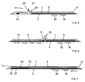
- the two sheets 1 and 3 are connected to one another at their four edges. Between the sheets 1 and 3, the intermediate sheet arrangement 5 is inserted and, as shown at 22, connected in the region of one sheet edge to at least one of the sheets, here with sheet 3, as if glued.
- One of the two sheets, sheet 1 has a pull-out slot 24 from which a transversely extended portion 25 of the intermediate sheet arrangement 5 projects.
- a field 18 to be labeled and a field 20 with information Y, such as a model solution, provided in advance on the sheet 3, are arranged relative to one another in such a way that the field 18 for the record X with respect to the information Y assigned to it is in the field 20 , closer to the edge area, which is opposite the connection 22, is arranged.
- the intermediate sheet arrangement 5 is closed by gripping the collar 25 Pulled out in the direction of the arrow, the field 18 is first released, whereupon the adhesive area 17 releases the two Sheets 1 and 3 are already glued and there they cannot be detached. Only then is field 20 released with advance information Y. If, for example, the solution entered in field 18 does not match the solution in field 20, a correction in field 18 is no longer possible, because the intermediate sheet arrangement 5 can no longer be pushed back there.
- a reinforcing element such as a thin wire, can be provided transversely to the intermediate sheet arrangement 5, as incorporated, as shown at 27. If the operative connection is designed to generate the recording contrast, as shown in FIG. 1, the carbonization 15 according to FIG. 1 is preferably only applied in the area provided for the recording XXX.
- FIG. 6 shows a further embodiment variant of the recording medium according to the invention, in principle again constructed as shown in FIG. 1 or 2, in which it is prevented that previously provided information Y can be viewed at an inappropriate time.
- the sheet 1 has a pull-out slot 31 in its central region, and the intermediate sheet arrangement 5, with a protruding pull-out collar 33, extends from this slot 31 on both sides between the sheets 1 and 3.
- the Intermediate sheet arrangement 5 is preferably nowhere connected to one of the sheets 1 or 3.
- the arrangement of a recording field 18 with respect to a field 20 with advance information is the same, as has already been explained with reference to FIG. 5.
- FIG. 7 shows a third, preferred variant, in which it is prevented that previously provided information Y can be viewed in a field 20 before recording information X in a field 18 can no longer be changed.
- sheets 1 and 3 are in turn joined together along three edges.
- the intermediate sheet arrangement 5 is connected in the open edge area to one of the sheets, as shown at 35, as glued, and protrudes between the sheets 1 and 3 to the opposite edge area with a lower sheet 5a.
- the lower sheet 5a is designed such that it does not stick to the adhesive layer 17, for example is siliconized.
- the sheet 5a merges into an upper sheet 5b, which runs back to the open edge area of the two sheets 1 and 3.
- This upper sheet 5b is preferably a carbon paper.
- This upper sheet 5b now forms a pull-out element, with the aid of which the entire intermediate sheet arrangement 5a, 5b can be drawn out between sheets 1 and 3, with simultaneous activation of the adhesive layer 17.
- the lower sheet 5a is formed stronger than the other sheets, nevertheless Of course extendable, and forms a writing pad for writing operations on sheet 1. It is entirely possible to carbonize the side of an intermediate sheet arrangement facing sheet 1 with only one sheet according to FIG.
- the recording medium can be used as a double recording medium, as already in connection with FIGS. 1 and 2 has been explained.
- the double sheet arrangements can also be connected, as shown at 40, in the case of a double version, as shown in dashed lines in FIGS. 1 and 2.
Landscapes
- Engineering & Computer Science (AREA)
- Physics & Mathematics (AREA)
- Educational Administration (AREA)
- Educational Technology (AREA)
- General Physics & Mathematics (AREA)
- Theoretical Computer Science (AREA)
- Business, Economics & Management (AREA)
- Credit Cards Or The Like (AREA)
- Developing Agents For Electrophotography (AREA)
- Holo Graphy (AREA)
- Photoreceptors In Electrophotography (AREA)
- Magnetic Record Carriers (AREA)
- Transition And Organic Metals Composition Catalysts For Addition Polymerization (AREA)
- Buildings Adapted To Withstand Abnormal External Influences (AREA)
- Prostheses (AREA)
- Mechanical Treatment Of Semiconductor (AREA)
- Thermal Transfer Or Thermal Recording In General (AREA)
- Duplication Or Marking (AREA)
- Folding Of Thin Sheet-Like Materials, Special Discharging Devices, And Others (AREA)
Claims (16)
Priority Applications (1)
| Application Number | Priority Date | Filing Date | Title |
|---|---|---|---|
| AT89102432T ATE79328T1 (de) | 1988-02-22 | 1989-02-13 | Aufzeichnungstraeger. |
Applications Claiming Priority (2)
| Application Number | Priority Date | Filing Date | Title |
|---|---|---|---|
| CH66388 | 1988-02-22 | ||
| CH663/88 | 1988-02-22 |
Publications (2)
| Publication Number | Publication Date |
|---|---|
| EP0330042A1 EP0330042A1 (fr) | 1989-08-30 |
| EP0330042B1 true EP0330042B1 (fr) | 1992-08-12 |
Family
ID=4192231
Family Applications (1)
| Application Number | Title | Priority Date | Filing Date |
|---|---|---|---|
| EP89102432A Expired - Lifetime EP0330042B1 (fr) | 1988-02-22 | 1989-02-13 | Support d'enregistrement |
Country Status (13)
| Country | Link |
|---|---|
| US (1) | US4932681A (fr) |
| EP (1) | EP0330042B1 (fr) |
| JP (1) | JPH0214180A (fr) |
| KR (1) | KR930007259B1 (fr) |
| CN (1) | CN1036530A (fr) |
| AT (1) | ATE79328T1 (fr) |
| AU (1) | AU616473B2 (fr) |
| BR (1) | BR8900753A (fr) |
| DE (1) | DE58902011D1 (fr) |
| IL (1) | IL89365A (fr) |
| NO (1) | NO890727L (fr) |
| PT (1) | PT89773B (fr) |
| ZA (1) | ZA891196B (fr) |
Families Citing this family (5)
| Publication number | Priority date | Publication date | Assignee | Title |
|---|---|---|---|---|
| US5090732A (en) * | 1990-05-14 | 1992-02-25 | Avant Incorporated | Inexpensive laminated universal sales presentation or security folder having many uses |
| US5100181A (en) * | 1990-05-14 | 1992-03-31 | Avant Incorporated | Low cost laminatable plastic envelope for easy customized self-lamination of greeting cards, memorabilia, and like displays |
| US5042843A (en) * | 1990-05-14 | 1991-08-27 | Avant Incorporated | Plastic display envelope for enabling subsequent lamination of large indicia bearing sheets and methods of making and using same |
| US5173081A (en) * | 1992-01-06 | 1992-12-22 | Moore Business Forms, Inc. | Security/protection feature business form with repositional adhesive |
| KR101036586B1 (ko) * | 2009-03-31 | 2011-05-24 | 주식회사 캠스 | 보강판이 인서트 사출된 차량용 범퍼의 백빔 구조 |
Family Cites Families (9)
| Publication number | Priority date | Publication date | Assignee | Title |
|---|---|---|---|---|
| US1117913A (en) * | 1912-08-16 | 1914-11-17 | Emanuel Rothschild | Manifold sales-check book. |
| FR1459401A (fr) * | 1965-10-29 | 1966-04-29 | Feuille de devoir à contrôle de la solution | |
| DE1797418A1 (de) * | 1968-09-26 | 1971-08-19 | Eduard Ritter | Lehreinrichtung (I) |
| DE2531331C3 (de) * | 1975-07-12 | 1979-10-31 | Eduard Zuerich Ritter (Schweiz) | Sammlung von Aufgabenblättern mit Lösungskontrolle |
| FR2383023A1 (fr) * | 1977-03-08 | 1978-10-06 | Herve & Fils Sa | Assemblage continu d'enveloppes scellees avec documents interieurs incorpores |
| US4248919A (en) * | 1979-04-26 | 1981-02-03 | Litton Business Systems, Inc. | Business form |
| US4621837A (en) * | 1985-01-31 | 1986-11-11 | Pamco Label Co. | Multi-layered label |
| WO1987003990A1 (fr) * | 1985-12-19 | 1987-07-02 | Woerndli Gerhard A | Procede pour l'enregistrement inalterable, support d'enregistrement et application du procede ou du support d'enregistrement |
| US4772049A (en) * | 1987-06-01 | 1988-09-20 | Ncr Corporation | Multiple ply document |
-
1989
- 1989-02-13 AT AT89102432T patent/ATE79328T1/de not_active IP Right Cessation
- 1989-02-13 EP EP89102432A patent/EP0330042B1/fr not_active Expired - Lifetime
- 1989-02-13 DE DE8989102432T patent/DE58902011D1/de not_active Expired - Lifetime
- 1989-02-15 AU AU29941/89A patent/AU616473B2/en not_active Ceased
- 1989-02-16 ZA ZA891196A patent/ZA891196B/xx unknown
- 1989-02-21 IL IL89365A patent/IL89365A/xx not_active IP Right Cessation
- 1989-02-21 PT PT89773A patent/PT89773B/pt active IP Right Grant
- 1989-02-21 US US07/313,397 patent/US4932681A/en not_active Expired - Fee Related
- 1989-02-21 KR KR1019890002045A patent/KR930007259B1/ko not_active Expired - Lifetime
- 1989-02-21 NO NO89890727A patent/NO890727L/no unknown
- 1989-02-21 BR BR898900753A patent/BR8900753A/pt unknown
- 1989-02-22 CN CN89101856A patent/CN1036530A/zh active Pending
- 1989-02-22 JP JP1040432A patent/JPH0214180A/ja active Pending
Also Published As
| Publication number | Publication date |
|---|---|
| DE58902011D1 (de) | 1992-09-17 |
| IL89365A0 (en) | 1989-09-10 |
| IL89365A (en) | 1992-02-16 |
| US4932681A (en) | 1990-06-12 |
| KR930007259B1 (ko) | 1993-08-04 |
| JPH0214180A (ja) | 1990-01-18 |
| CN1036530A (zh) | 1989-10-25 |
| EP0330042A1 (fr) | 1989-08-30 |
| NO890727L (no) | 1989-08-23 |
| BR8900753A (pt) | 1989-10-17 |
| AU616473B2 (en) | 1991-10-31 |
| AU2994189A (en) | 1989-08-24 |
| PT89773A (pt) | 1989-10-04 |
| PT89773B (pt) | 1994-02-28 |
| ATE79328T1 (de) | 1992-08-15 |
| KR890013609A (ko) | 1989-09-25 |
| NO890727D0 (no) | 1989-02-21 |
| ZA891196B (en) | 1989-10-25 |
Similar Documents
| Publication | Publication Date | Title |
|---|---|---|
| DE2504210C2 (de) | Windelverschluß | |
| DE2261606B2 (de) | Klebebefestigung für Blattmaterial | |
| EP0245325A1 (fr) | Procede d'application d'adhesifs. | |
| EP0250398B1 (fr) | Procede pour l'enregistrement inalterable, support d'enregistrement et application du procede ou du support d'enregistrement | |
| DE69500986T2 (de) | Bindeelement für Blätter | |
| DE3021989C2 (de) | Versandtasche, insbesondere Briefumschlag | |
| DE102008018517A1 (de) | Drehbares Etikett, Vorrichtung und Verfahren zum Anbringen des drehbaren Etiketts | |
| EP0330042A1 (fr) | Support d'enregistrement | |
| DE2504298C2 (de) | Windelverschluß für eine Wegwerfwindel | |
| DE1961040A1 (de) | Haftbindemappe | |
| DE2805689C3 (de) | Schreibblock | |
| CH602352A5 (en) | Endless web for carrying envelopes to be addressed | |
| EP0681530B1 (fr) | Reliure a anneaux munie d'un rabat a 6 ou a 8 cotes | |
| DE3844201C1 (en) | Closure and identification seal | |
| DE3434184A1 (de) | Verfahren zum einkleben von werbe- und/oder informationsschriften u.dgl. in zeitschriften sowie hierbei verwendbare leporello-werbeschrift | |
| DE3112600C2 (de) | Schablone | |
| EP0547490B1 (fr) | Livre sous forme de brochure | |
| DE2750880C2 (de) | Selbstklebendes Erzeugnis | |
| EP0233491B1 (fr) | Coupe pour une pochette de disque en papier avec un revêtement intérieur fait d'une double pellicule de plastic | |
| DE3322477A1 (de) | Wand zur bildung eines behaelters | |
| DE7704878U1 (de) | Sammelalbum | |
| DE2701714B2 (de) | Verleimter Formularsatz | |
| DE1927176C (de) | Endloser Durchschreibesatz | |
| DE19715800A1 (de) | Zurichtstreifen zum Rillen von Kartonagen | |
| DE2419852C3 (de) | Schreibsatz und Verfahren zu dessen Herstellung |
Legal Events
| Date | Code | Title | Description |
|---|---|---|---|
| PUAI | Public reference made under article 153(3) epc to a published international application that has entered the european phase |
Free format text: ORIGINAL CODE: 0009012 |
|
| AK | Designated contracting states |
Kind code of ref document: A1 Designated state(s): AT BE CH DE ES FR GB GR IT LI LU NL SE |
|
| 17P | Request for examination filed |
Effective date: 19890814 |
|
| 17Q | First examination report despatched |
Effective date: 19910117 |
|
| GRAA | (expected) grant |
Free format text: ORIGINAL CODE: 0009210 |
|
| AK | Designated contracting states |
Kind code of ref document: B1 Designated state(s): AT BE CH DE ES FR GB GR IT LI LU NL SE |
|
| PG25 | Lapsed in a contracting state [announced via postgrant information from national office to epo] |
Ref country code: IT Free format text: LAPSE BECAUSE OF FAILURE TO SUBMIT A TRANSLATION OF THE DESCRIPTION OR TO PAY THE FEE WITHIN THE PRE;WARNING: LAPSES OF ITALIAN PATENTS WITH EFFECTIVE DATE BEFORE 2007 MAY HAVE OCCURRED AT ANY TIME BEFORE 2007. THE CORRECT EFFECTIVE DATE MAY BE DIFFERENT FROM THE ONE RECORDED.SCRIBED TIME-LIMIT Effective date: 19920812 Ref country code: ES Free format text: THE PATENT HAS BEEN ANNULLED BY A DECISION OF A NATIONAL AUTHORITY Effective date: 19920812 Ref country code: BE Effective date: 19920812 Ref country code: SE Free format text: THE PATENT HAS BEEN ANNULLED BY A DECISION OF A NATIONAL AUTHORITY Effective date: 19920812 Ref country code: GB Effective date: 19920812 Ref country code: GR Free format text: LAPSE BECAUSE OF FAILURE TO SUBMIT A TRANSLATION OF THE DESCRIPTION OR TO PAY THE FEE WITHIN THE PRESCRIBED TIME-LIMIT Effective date: 19920812 Ref country code: NL Effective date: 19920812 |
|
| REF | Corresponds to: |
Ref document number: 79328 Country of ref document: AT Date of ref document: 19920815 Kind code of ref document: T |
|
| REF | Corresponds to: |
Ref document number: 58902011 Country of ref document: DE Date of ref document: 19920917 |
|
| EN | Fr: translation not filed | ||
| PG25 | Lapsed in a contracting state [announced via postgrant information from national office to epo] |
Ref country code: FR Effective date: 19921231 |
|
| NLV1 | Nl: lapsed or annulled due to failure to fulfill the requirements of art. 29p and 29m of the patents act | ||
| PG25 | Lapsed in a contracting state [announced via postgrant information from national office to epo] |
Ref country code: AT Effective date: 19930213 |
|
| GBV | Gb: ep patent (uk) treated as always having been void in accordance with gb section 77(7)/1977 [no translation filed] |
Effective date: 19920812 |
|
| PG25 | Lapsed in a contracting state [announced via postgrant information from national office to epo] |
Ref country code: LU Free format text: LAPSE BECAUSE OF NON-PAYMENT OF DUE FEES Effective date: 19930228 |
|
| PLBE | No opposition filed within time limit |
Free format text: ORIGINAL CODE: 0009261 |
|
| STAA | Information on the status of an ep patent application or granted ep patent |
Free format text: STATUS: NO OPPOSITION FILED WITHIN TIME LIMIT |
|
| 26N | No opposition filed | ||
| PG25 | Lapsed in a contracting state [announced via postgrant information from national office to epo] |
Ref country code: DE Effective date: 19931103 |
|
| REG | Reference to a national code |
Ref country code: FR Ref legal event code: ST |
|
| PGFP | Annual fee paid to national office [announced via postgrant information from national office to epo] |
Ref country code: CH Payment date: 19940831 Year of fee payment: 6 |
|
| PG25 | Lapsed in a contracting state [announced via postgrant information from national office to epo] |
Ref country code: CH Effective date: 19950228 Ref country code: LI Effective date: 19950228 |