EP0329136A2 - Luggage carrier for two-wheeled vehicles - Google Patents
Luggage carrier for two-wheeled vehicles Download PDFInfo
- Publication number
- EP0329136A2 EP0329136A2 EP89102681A EP89102681A EP0329136A2 EP 0329136 A2 EP0329136 A2 EP 0329136A2 EP 89102681 A EP89102681 A EP 89102681A EP 89102681 A EP89102681 A EP 89102681A EP 0329136 A2 EP0329136 A2 EP 0329136A2
- Authority
- EP
- European Patent Office
- Prior art keywords
- cover
- trough
- luggage
- luggage carrier
- luggage rack
- Prior art date
- Legal status (The legal status is an assumption and is not a legal conclusion. Google has not performed a legal analysis and makes no representation as to the accuracy of the status listed.)
- Granted
Links
Images


Classifications
-
- B—PERFORMING OPERATIONS; TRANSPORTING
- B62—LAND VEHICLES FOR TRAVELLING OTHERWISE THAN ON RAILS
- B62J—CYCLE SADDLES OR SEATS; AUXILIARY DEVICES OR ACCESSORIES SPECIALLY ADAPTED TO CYCLES AND NOT OTHERWISE PROVIDED FOR, e.g. ARTICLE CARRIERS OR CYCLE PROTECTORS
- B62J7/00—Luggage carriers
- B62J7/02—Luggage carriers characterised by the arrangement thereof on cycles
- B62J7/04—Luggage carriers characterised by the arrangement thereof on cycles arranged above or behind the rear wheel
-
- B—PERFORMING OPERATIONS; TRANSPORTING
- B62—LAND VEHICLES FOR TRAVELLING OTHERWISE THAN ON RAILS
- B62J—CYCLE SADDLES OR SEATS; AUXILIARY DEVICES OR ACCESSORIES SPECIALLY ADAPTED TO CYCLES AND NOT OTHERWISE PROVIDED FOR, e.g. ARTICLE CARRIERS OR CYCLE PROTECTORS
- B62J9/00—Containers specially adapted for cycles, e.g. panniers or saddle bags
- B62J9/20—Containers specially adapted for cycles, e.g. panniers or saddle bags attached to the cycle as accessories
- B62J9/21—Containers specially adapted for cycles, e.g. panniers or saddle bags attached to the cycle as accessories above or alongside the front wheel, e.g. on the handlebars
-
- B—PERFORMING OPERATIONS; TRANSPORTING
- B62—LAND VEHICLES FOR TRAVELLING OTHERWISE THAN ON RAILS
- B62J—CYCLE SADDLES OR SEATS; AUXILIARY DEVICES OR ACCESSORIES SPECIALLY ADAPTED TO CYCLES AND NOT OTHERWISE PROVIDED FOR, e.g. ARTICLE CARRIERS OR CYCLE PROTECTORS
- B62J9/00—Containers specially adapted for cycles, e.g. panniers or saddle bags
- B62J9/20—Containers specially adapted for cycles, e.g. panniers or saddle bags attached to the cycle as accessories
- B62J9/23—Containers specially adapted for cycles, e.g. panniers or saddle bags attached to the cycle as accessories above or alongside the rear wheel
-
- B—PERFORMING OPERATIONS; TRANSPORTING
- B62—LAND VEHICLES FOR TRAVELLING OTHERWISE THAN ON RAILS
- B62J—CYCLE SADDLES OR SEATS; AUXILIARY DEVICES OR ACCESSORIES SPECIALLY ADAPTED TO CYCLES AND NOT OTHERWISE PROVIDED FOR, e.g. ARTICLE CARRIERS OR CYCLE PROTECTORS
- B62J9/00—Containers specially adapted for cycles, e.g. panniers or saddle bags
- B62J9/20—Containers specially adapted for cycles, e.g. panniers or saddle bags attached to the cycle as accessories
- B62J9/24—Containers specially adapted for cycles, e.g. panniers or saddle bags attached to the cycle as accessories on specially adapted racks, e.g. for top or side cases
-
- B—PERFORMING OPERATIONS; TRANSPORTING
- B62—LAND VEHICLES FOR TRAVELLING OTHERWISE THAN ON RAILS
- B62J—CYCLE SADDLES OR SEATS; AUXILIARY DEVICES OR ACCESSORIES SPECIALLY ADAPTED TO CYCLES AND NOT OTHERWISE PROVIDED FOR, e.g. ARTICLE CARRIERS OR CYCLE PROTECTORS
- B62J9/00—Containers specially adapted for cycles, e.g. panniers or saddle bags
- B62J9/30—Containers specially adapted for cycles, e.g. panniers or saddle bags characterised by locking arrangements, e.g. top case locks integrated in a vehicle central locking system
Abstract
Description
Die Erfindung betrifft einen Gepäckträger für Zweiradfahrzeuge mit an einer Auflagefläche vorgesehenem und zu wenigstens einem Festpunkt am Zweiradfahrzeug verlaufendem Gestänge sowie mit unter der Auflagefläche an Gleitbahnen angeordnetem und in Längsrichtung daran verschiebbarem Schubkasten, insbesondere mit einem Schubkasten, der im Boden eine Längseinformung zur Aufnahme eines Abschnittes eines Schutzbleches od. dgl. aufweist.The invention relates to a luggage rack for two-wheeled vehicles with a linkage provided on a support surface and extending to at least one fixed point on the two-wheeled vehicle, and with a drawer arranged under the support surface on slideways and displaceable in the longitudinal direction thereon, in particular with a drawer which has a longitudinal indentation in the floor for receiving a section a mudguard or the like.
Ein derartiger Gepäckträger ist aus der DE-PS 381 803 bekannt; unter einem Gepäckrost oder einer Gepäckplatte ist eine Schublade angebracht, welche mit seitlichen Auskragungen in von den Trägerlängskanten abkragende Nutwülste des Gepäckrostes eingreifen. Letzterer ist zum einen mit zwei Gestängen aus Bandmaterial an der Radnabe sowie zum anderen mit einem zusätzlichen Winkelstück an einem aufragenden Gestängeteil des Fahrzeuges festgelegt.Such a luggage rack is known from DE-PS 381 803; Under a luggage rack or a luggage rack there is a drawer which, with lateral projections, engages in groove ridges of the luggage rack which project from the longitudinal edges of the carrier. The latter is fixed on the one hand to the wheel hub with two linkages made of band material and on the other hand with an additional angle piece on an upstanding linkage part of the vehicle.
Einen unter einem Gepäckträger verschiebbaren Verbandskasten zeigt zudem DE-GM 81 35 492.DE-GM 81 35 492 also shows a first-aid kit that can be moved under a luggage rack.
Der Nachteil dieser bekannten Konstruktion liegt vor allem darin, daß sie den modernen Anforderungen an Betriebssicherheit und an günstige Strömungswerte nicht gerecht werden, weshalb sich der Erfinder das Ziel gesetzt hat, einen neuen und erheblich verbesserten Gepäckträger unter Meidung der erkannten Mängel zu schaffen.The disadvantage of this known construction is primarily that it does not meet the modern requirements for operational safety and favorable flow values, which is why the inventor has set itself the goal of creating a new and significantly improved luggage rack while avoiding the identified defects.
Zur Lösung dieser Aufgabe führt, daß dieser Gepäckträger aus einem am Gestänge festliegenden und die Auflagefläche -- mit zumindest einer pultartigen Schmalseite -- anbietenden Deckel sowie einer an dessen Unterfläche in Führungsschienen angebrachten Wanne als Schublade besteht, die in Schließlage zumindest einem Anschlag des Deckels anliegt und mit diesem einen schachtelartigen einheitlichen Körper bildet, wobei die Wanne ein Schließelement aufweist, das in Schließlage am Deckel verriegelbar ist. Dabei hat es sich als besonders günstig erwiesen, den Deckel und die Wanne mit ihren angeformten Führungsschienen jeweils aus Kunststoff zu formen oder aus einem Leichtmetall, insbesondere aus einer Aluminiumlegierung.The solution to this problem is that this luggage rack consists of a cover which is fixed to the linkage and which offers the support surface - with at least one desk-like narrow side - and a tub attached to the undersurface in guide rails as a drawer which, in the closed position, bears against at least one stop of the cover and forms with it a box-like unitary body, the tub having a closing element which can be locked in the closed position on the lid. It has proven to be particularly advantageous to form the cover and the trough with their molded guide rails each from plastic or from a light metal, in particular from an aluminum alloy.
Es entsteht so ein einheitlicher Formkörper, der eine Unterteilung in Deckel und Wanne nur durch die Trennfuge im Bereich der Führungsschienen erkennen läßt. Der zweiteilige erfindungsgemäße Gepäckträger ist in geschlossener Lage ohne Vorsprünge an den Seitenwänden und zudem durch die pultartige ausgebildete Schmalseite ausreichend windschlüpfrig. Den Sicherheitswünschen des Benutzers wird durch die glatten Außenflächen sowie die Verriegelbarkeit des Deckels Rechnung getragen.The result is a uniform molded body that only shows a subdivision into the lid and pan through the joint in the area of the guide rails. The two-part luggage rack according to the invention is in the closed position without projections on the side walls and also due to the desk-shaped narrow side sufficiently slip. The safety requirements of the user are taken into account by the smooth outer surfaces and the lockability of the lid.
Zur Stabilisierung der verhältnismäßig dünnen Auflageplatte des Deckels sind dieser nach unten weisende vertikale Rippen angeformt sowie zwei Seiten- oder Flankenflächen, welche jeweils eine Führungsschiene aufnehmen, in die eine Gegenschiene der Wanne eingreift. Da sich diese Führungsschienen-Paarungen innerhalb der Seitenflächen des Deckels befinden, werden Außenwulste oder ähnliche Abkragungen vermieden.In order to stabilize the relatively thin support plate of the lid, the downward-facing vertical ribs are formed on it, as well as two side or flank surfaces, each of which receives a guide rail into which a counter rail of the tub engages. Since these pair of guide rails are located within the side surfaces of the cover, outer beads or similar protrusions are avoided.
Desweiteren dient den besseren Strömungswerten die Maßgabe, wonach Deckel und Wanne zumindest zu einer Schmalseite hin sich in Draufsicht verjüngen.In addition, the better flow values are served by the stipulation that the cover and trough at least narrow towards a narrow side in plan view.
Der Deckel weist erfindungsgemäß im Verjüngungsbereich eine zur Auflagefläche geneigte sowie eine gegenläufige Pultfläche auf. Diese bilden einen nach oben gerichteten Kamm, der von der Auflagefläche aufragt und eine Begrenzung für Gepäckstücke darstellt. Außerdem ist die Wanne im Verjüngungsbereich mit einer bodenwärts geneigten Bugunterfläche versehen. Diese Ausgestaltung von Deckel und Wanne ergibt eine schiffsbugähnliche Form des einen Trägerendes, die als besonders günstige Ausgestaltung im Rahmen der gesehenen Aufgabe zu betrachten ist. Auch die Heckseite des erfindungsgemäßen Gepäckträgers ist verjüngt, dies bevorzugt bis zu einer Heckfläche, welche wenigstens einen Rückstrahler aufnimmt. Dieser ist also Teil der Wanne bzw. Schublade und aus Sicherheitsgründen besonders großflächig gestaltet.According to the invention, the cover has a desk surface inclined to the support surface and an opposing desk surface in the tapered area. These form an upward-facing comb that rises from the support surface and represents a limitation for items of luggage. In addition, the trough in the tapered area is provided with a bow lower surface sloping downwards. This configuration of the lid and trough results in a bow-like shape of the one beam end, which is to be regarded as a particularly favorable configuration in the context of the task seen. The rear side of the luggage rack according to the invention is also tapered, preferably up to a rear surface which receives at least one reflector. This is part of the tub or drawer and is designed to be particularly large for safety reasons.
Im übrigen hat es sich als günstig erwiesen, in den Deckel -- bevorzugt aber in den Wannenkörper -- seitliche Blinklichter zu integrieren, damit solche auch bei Zweirädern ohne auskragende Arme Verwendung finden können.Incidentally, it has proven to be advantageous to integrate side flashing lights in the lid, but preferably in the tub body, so that they can also be used in two-wheelers without cantilever arms.
Üblicherweise wird der Gepäckträger so am Fahrzeugheck installiert, daß die Wanne nach hinten herausziehbar ist; aus diesem Grund ist auch -- wie gesagt -- an ihrer Heckfläche der Rückstrahler vorgesehen. Jedoch ist es ebenso möglich -- und dieses ist eine neue Verwendungsweise von Gepäckträgern -- , die beschriebene Heckfläche der Wanne mit einem Scheinwerfer auszurüsten und den Gepäckträger mit in Fahrtrichtung weisendem Scheinwerfer am Vorderrad festzulegen; in diesem Falle ist die Wanne oder Schublade nach vorne hin ausziehbar.The luggage rack is usually installed on the rear of the vehicle so that the tub can be pulled out to the rear; for this reason, as already mentioned, the rear reflector is provided on its rear surface. However, it is also possible - and this is a new way of using luggage carriers - to equip the described rear surface of the tub with a headlight and to fix the luggage carrier with the headlight pointing in the direction of travel on the front wheel; in this case the tub or drawer can be pulled out towards the front.
Der erfindungsgemäße Gepäckträger mit seiner windschlüpfrigen und einheitlichen Formgebung erlaubt die Adaption von Zusatzteilen wie Schultaschen, Gepäcktaschen, Kindersitzen od.dlg.; diese Zusatzteile sind mit Anschlußstücken versehen, die in Anschlußorgane des Deckels eingreifen. Dieser ist dazu mit bevorzugt schlüssellochartigen Anschlußlöchern versehen, denen jeweils ein Schließbolzen zugeordnet ist; letzterer ist Teil der Wanne und wird mit dieser soweit verschoben, daß er in Schließstellung das Anschlußloch teilweise überdeckt. Dabei wird das Anschlußorgan des Zusatzteiles im Anschlußloch festgeklemmt. Da -- wie beschrieben -- die Wanne verschließbar ausgebildet ist, wird durch das Verschließen der Wanne gleichzeitig auch der Zusatzteil gesichert.The luggage rack according to the invention with its streamlined and uniform shape allows the adaptation of additional parts such as school bags, luggage bags, child seats or the like; these additional parts are provided with connecting pieces which engage in connecting members of the cover. For this purpose, this is preferably provided with keyhole-like connection holes, each of which is assigned a locking bolt; the latter is part of the tub and is moved with it so far that it partially covers the connection hole in the closed position. The connecting element of the additional part is clamped in the connection hole. Since - as described - the tub is designed to be lockable, the additional part is also secured by closing the tub.
Die Befestigung des erfindungsgemäßen Gepäckträgers erfolgt zum oberen Abschnitt der Radgabel hin mittels eines Winkelstückes oder eines Bügels, die im Deckel so befestigt sind, daß diese Verbindungsstelle bei geschlossener Wanne nicht zugänglich ist. Da der Abstand zwischen dem Gepäckträger einerseits und dem an die Radgabel angeschlossenen Schenkel des Winkelstückes verhältnismäßig gering bleibt, ist auch das Winkelstück selbst ohne ein Herausziehen der Wanne vom Zweiradfahrzeug nicht lösbar. Damit wird eine sichere Befestigung am Zweiradfahrzeug erreicht.The luggage carrier according to the invention is attached to the upper section of the wheel fork by means of an angle piece or a bracket, which are fastened in the lid in such a way that this connection point is not accessible when the tub is closed. Since the distance between the luggage rack on the one hand and the leg of the contra-angle handpiece connected to the wheel fork remains relatively small, even the contra-angle handpiece cannot be detached from the two-wheeled vehicle even without the tub being pulled out. This ensures a secure attachment to the two-wheeled vehicle.
Erfindungsgemäß ist der Deckel also einerseits mittels des Winkelstückes sowie anderseits durch das Gestänge fester Teil des Zweiradfahrzeuges und in der Verlängerung seiner Pultfläche an der unteren Deckelkontur mit einem Schulterabsatz ausgestattet, der den Anschlag für eine entsprechende Stufung des Wannenrandes bildet. Dieser Anschlag ist erforderlich, um die Wanne in ihrer Schließstellung zu fixieren und damit auch in der Verschlußstellung der beschriebenen Schließbolzen.According to the invention, the lid is thus equipped on the one hand by means of the angle piece and on the other hand by the linkage fixed part of the two-wheeled vehicle and in the extension of its desk surface on the lower lid contour with a shoulder heel, which forms the stop for a corresponding gradation of the tub rim. This stop is necessary to fix the tub in its closed position and thus also in the closed position of the locking bolts described.
Von zusätzlicher Bedeutung ist die paarweise Zuordnung der Anschlußlöcher, von denen eines in der Auflagefläche und das andere in der Seitenwand des Deckels vorgesehen ist, wobei beide Anschlußlöcher durch einen gemeinsamen Aufnahmeraum für ein Anschlußorgan des Zusatzteiles verbunden sind, weshalb auch nur ein Schließbolzen für ein Paar von Anschlußlöchern ausreicht. Die Konstruktion und Fertigung wird hierdurch vereinfacht.Of additional importance is the paired assignment of the connection holes, one of which is provided in the support surface and the other in the side wall of the cover, both connection holes being connected by a common receiving space for a connecting element of the additional part, which is why only one locking bolt for a pair of connection holes is sufficient. This simplifies the design and manufacture.
Zu den Sicherheitseinrichtungen des erfindungsgemäßen Gepäckträgers gehören auch -- an sich bekannte -- flexible Zurrstränge, welche über die Auflagefläche laufen. Diese sind einends in der Pultfläche des Deckels festgelegt und andernends durch ein Griffstück verbunden, welches mittels Hakenelementen am Gepäckträgerheck festgelegt werden kann. Diese Zurrstränge sind in üblicher Weise längenveränderlich und womit ihre Haltekraft einstellbar ist.The safety devices of the luggage carrier according to the invention also include - known per se - flexible lashing strands which run over the bearing surface. These are fixed at one end in the desk surface of the cover and at the other end connected by a handle which can be fixed to the rear of the luggage rack by means of hook elements. These lashing strands are variable in length in the usual way and with which their holding force can be adjusted.
Zur Erhöhung der Betriebssicherheit sowie zur einfacheren Montage führt die Ausgestaltung eines Schuhes, welcher die freien Enden des Gestänges einer Gepäckträgerseite aufnimmt und der im Nabenbereich festlegbar ist. Dank einer exzentrischen Anordnung seines Befestigungselements an einer Fahne kann das Gestänge problemlos an unterschiedliche Fahrzeugmaße angepaßt werden. Im übrigen wird auf die Ansprüche 27 bis 31 verwiesen.The design of a shoe, which receives the free ends of the linkage on one side of the luggage rack and which can be fixed in the hub area, leads to increased operational safety and to easier assembly. Thanks to an eccentric arrangement of its fastener on a flag, the linkage can be easily adapted to different vehicle dimensions. For the rest, reference is made to claims 27 to 31.
Die Erfindung betrifft auch einen Gepäckträger für Zweiradfahrzeuge, umfassend
- einen sich am Zweiradfahrzeug, vorzugsweise über ein Gestänge, abstützenden Deckel (Gepäckträgerplatte), dessen Oberseite mit einer Auflagefläche zur Aufnahme von Lasten ausgebildet ist,
- eine an dem Deckel schubladenartig geführte Wanne,
- wenigstens ein schlüssellochartiges Anschlußloch im Deckel zur lösbaren Anbringung einer Zusatzeinrichtung, insbesondere Seitentasche, Kindersitz oder dergl., über jeweils einen an der Zusatzeinrichtung angebrachten Anschlußkörper,
- eine Schließeinrichtung für das wenigstens eine Anschlußloch mit einem Schließteil, welches in einer Öffnungsstellung der Schließeinrichtung den weiten Lochabschnitt des Anschlußloches freigibt zum Einsetzen bzw. Herausnehmen eines Anschlußkopfes des Anschlußkörpers in einen bzw. aus dem Aufnahmeraum des Deckels unterhalb des Anschlußloches, und welches in einer Schließstellung der Schließeinrichtung in den Aufnahmeraum im Bereich des weiten Lochabschnitts einrückt zur Festlegung des Anschlußkörpers im engen Lochabschnitt des Anschlußloches,
- ein Schließelement, insbesondere Zylinderschloß, zur sperrenden Festlegung der Wanne in einer Einschubstellung am Deckel und zur sperrenden Festlegung der Schließeinrichtung in ihrer Schließstellung.The invention also relates to a luggage rack for two-wheeled vehicles, comprising
a cover (luggage carrier plate), which is supported on the two-wheeled vehicle, preferably via a linkage, the upper side of which is formed with a support surface for receiving loads,
- a tub that is drawer-like on the lid,
at least one keyhole-like connection hole in the cover for the detachable attachment of an additional device, in particular a side pocket, child seat or the like, via in each case one connector body attached to the additional device,
- A locking device for the at least one connection hole with a locking part, which in an open position of the locking device releases the wide hole section of the connection hole for inserting or removing a connection head of the connection body into or from the receiving space of the cover below the connection hole, and which in a Closed position of the locking device engages in the receiving space in the area of the wide hole section to fix the connection body in the narrow hole section of the connection hole,
- A locking element, in particular a cylinder lock, for locking the trough in a retracted position on the cover and for locking the locking device in its closed position.
Ein derartiger Gepäckträger ist bekannt (DE-A-35 13 878). Die Schließeinrichtung wird hier von Bolzen 90 gebildet, die starr an einem Querbügel 48 befestigt sind, welcher wiederum das Zylindergehäuse eines Zylinderschlosses aufnimmt. Normalerweise befindet sich der Querbügel samt den Bolzen 90 in seiner Einfahrstellung (Schließstellung der Schließeinrichtung). In dieser Stellung kann durch Verdrehen des Schlüssels die Wanne völlig unabhängig von der Schließeinrichtung bewegt werden. Zum Herausnehmen bzw. Einsetzen eines Anschlußkopfes eines Anschlußkörpers 102 wird das Zylinderschloß zuerst in Freigabestellung verdreht und anschließend samt Querbügel 48 nach außen in die Öffnungsstellung gezogen. Auch in dieser Stellung der Schließeinrichtung kann die Wanne 56 frei hin und her bewegt werden.Such a luggage rack is known (DE-A-35 13 878). The locking device is formed here by
Um die Bedienung der Schließeinrichtung zu vereinfachen wird vorgeschlagen, daß die Wanne mit der Schließeinrichtung derart verkoppelt ist, daß sie bei Übergang in ihre Einschubstellung die Schließeinrichtung in ihre Schließstellung bewegt. Auf diese Weise wird erreicht, daß die Schließeinrichtung beim Wanneneinschub automatisch in die Schließstellung bewegt wird und umgekehrt bei Wannenauszug in die Öffnungsstellung bewegt wird, so daß die beim Stand der Technik erforderliche zusätzliche Bedienung des die Schließbolzen tragenden Bügels entfällt. Die Gefahr, daß bei ausgezogener Wanne die Zusatzeinrichtung sich unbeabsichtigt vom Gepäckträger löst, besteht nicht, da hierzu die Zusatzeinrichtung zuerst in Längsrichtung des jeweiligen Anschlußloches zu schieben und anschließend vom Deckel weg zu bewegen ist.In order to simplify the operation of the locking device, it is proposed that the trough be coupled to the locking device in such a way that it moves the locking device into its closed position upon transition into its insertion position. In this way it is achieved that the locking device is automatically moved into the closed position when the bathtub is inserted and, conversely, is moved into the open position when the bathtub is pulled out, so that the additional operation of the bracket carrying the locking bolt required in the prior art is eliminated. There is no danger that the additional device will unintentionally detach itself from the luggage rack when the tub is pulled out, since for this purpose the additional device must first be pushed in the longitudinal direction of the respective connection hole and then moved away from the cover.
In einer ersten Ausführungsform der Erfindung ist vorgesehen, daß die Wanne starr mit einem das Schließteil bildenden Schließbolzen verbunden ist. Diese Ausführungsform zeichnet sich durch besonders einfachen Aufbau aus. Jedoch setzt diese Lösung entsprechenden Bewegungsraum, insbesondere eine entsprechende weite und langgestreckte Schließbolzen-Aufnahmenut, im Deckel voraus. Auch ist der Schließbolzen bei herausgezogener Wanne sichtbar.In a first embodiment of the invention it is provided that the trough is rigidly connected to a locking bolt forming the locking part. This embodiment is characterized by a particularly simple structure. However, this solution requires corresponding movement space, in particular a corresponding wide and elongated locking pin receiving groove, in the cover. The locking bolt is also visible when the tub is pulled out.
Eine diese Nachteile vermeidende Lösung ist gekennzeichnet durch einen am Deckel schwenkbar gelagerten Doppelarm hebel, dessen einer Arm als das Schließteil ausgebildet ist und an dessen anderen Arm die Wanne bei der Annäherung an ihre Einschubstellung anschlägt zur Schwenkbewegung des Doppelarms in die Schließstellung des Schließteils.A solution avoiding these disadvantages is characterized by a double arm pivotably mounted on the cover lever, one arm of which is designed as the closing part and the other arm of the tub strikes when approaching its insertion position for pivoting the double arm into the closed position of the closing part.
Eine besonders einfache Übertragungsmechanik mit Rückfederung der Schließeinrichtung in ihre Öffnungsstellung bei Ausschub der Wanne wird erfindungsgemäß erreicht durch einen am Deckel gehalterten Federbügel, welcher an das schwenkbewegliche oder linearbewegliche Schließteil angreift, und an welchen die Wanne bei Annäherung an ihre Einschubstellung anschlägt. Hierbei kann vorgesehen sein, daß der Federbügel im wesentlichen schleifenförmig ausgebildet ist, daß wenigstens einer zweier einander gegenüberliegender Seitenschenkel des Federbügels mit einem Schließteil verkoppelt ist, daß einer der beiden die Seitenschenkel verbindenden Verbindungsschenkel am Deckel gehaltert ist, und daß die Wanne bei Annäherung an ihre Einschubstellung an den anderen Verbindungsschenkel anschlägt und ihn bei weiterer Bewegung auf ihre Einschubstellung zu in Richtung zum einen Verbindungsschenkel drückt. Der Federbügel sorgt für die federnde Vorspannung der Schließeinrichtung in ihre Öffnungsstellung sowie gleichzeitig für die Kraftübertragung mit Kraftumlenkung von der Schublade auf das jeweilige Schließteil, wobei auch eine besonders einfach zu realisierende und sicher sperrende Linearbewegung des Schließteils (in diese Richtung senkrecht zur Bedienungsrichtung der Schublade) in Frage kommt. Der Federbügel kann zur gleichzeitigen Betätigung zweier Schließteile eingesetzt werden. Es ergibt sich eine geringe Bauhöhe der Anordnung aus Federbügel und Schließteil, so daß diese Anordnung ohne weiteres an der Unterseite des Deckels angebracht werden kann ohne hierbei den Wannenauszug zu behindern.A particularly simple transmission mechanism with spring-back of the locking device into its open position when the tub is extended is achieved according to the invention by a spring clip held on the lid, which engages the pivoting or linearly movable closing part, and against which the tub strikes when it approaches its insertion position. It can be provided that the spring clip is essentially loop-shaped, that at least one of two opposite side legs of the spring clip is coupled to a closing part, that one of the two connecting legs connecting the side legs is held on the lid, and that the tub when approaching hers Insert position strikes against the other connecting leg and presses it toward its insertion position toward a connecting leg as it moves further. The spring clip ensures the spring tension of the locking device in its open position and at the same time for the power transmission with power deflection from the drawer to the respective locking part, whereby a particularly easy to implement and safely locking linear movement of the locking part (in this direction perpendicular to the operating direction of the drawer) can be considered. The spring clip can be used to actuate two locking parts at the same time. There is a low overall height of the arrangement of spring clip and closing part, so that this arrangement can be easily attached to the underside of the lid without hindering the tub pull-out.
Zur sicheren Führung des Federbügels wird vorgeschlagen, daß der andere Verbindungsschenkel mit einer Zusatz- Federbügelschlaufe ausgebildet ist, die ein zur Bewegungsrichtung der Schublade paralleles Langloch bildet, und daß in das Langloch ein am Deckel befestigter Führungsbolzen eingreift.For safe guidance of the spring clip, it is proposed that the other connecting leg be equipped with an additional Spring clip loop is formed, which forms a slot parallel to the direction of movement of the drawer, and that engages in the slot a guide bolt attached to the lid.
Bei dem bekannten Gepäckträger (DE-A-35 14 878) sind die beiden nach außen abgewinkelten Wannenlängsränder jeweils in einer integral mit dem Deckel ausgebildeten Führungsleiste an der Deckelunterseite geführt.In the known luggage rack (DE-A-35 14 878), the two outwardly angled tub longitudinal edges are each guided in a guide bar integrally formed with the lid on the underside of the lid.
Um bei ansprechendem Äußeren für hohe mechanische Belastbarkeit des Gepäckträgers zu sorgen mit der Möglichkeit für Deckel und/oder Wanne auch kostengünstiges, mechanisch geringer beanspruchbares Material, wie z.B. Kunststoff, einsetzen zu können, wird vorgeschlagen, daß längs des Deckelrandes in vorzugsweise geschlossener Schleife eine gesonderte Profilschiene verläuft, und daß die zur Bewegungsrichtung der Schublade parallelen Längsseiten-Abschnitte der Profilschiene als Führungsschiene für einen Rand der Wanne ausgebildet sind. Die Führungsprofilschiene kann von einem Metallprofil gebildet sein.In order to ensure a high mechanical load-bearing capacity of the luggage rack with an appealing exterior, with the option of a lid and / or tub, it is also possible to use inexpensive, less mechanically stressable material, such as Plastic, to be able to use, it is proposed that a separate profile rail runs along the edge of the lid in a preferably closed loop, and that the longitudinal side sections of the profile rail parallel to the direction of movement of the drawer are designed as a guide rail for an edge of the tub. The guide rail can be formed by a metal profile.
Vorzugsweise ist hierbei vorgesehen, daß die Profilschiene im Querschnitt einem Doppel-C-Profil entspricht mit jeweils einer Ausfräsung im Bereich eines Endes der beiden Längsseitenabschnitte zum Herausleiten des Wannenrandes aus der Profilschiene. Ein derartiges Profil ist kostengünstig erhältlich und in einfacher Weise mit dem Deckel sowie dem Wannenrand zu verbinden.It is preferably provided here that the profile rail corresponds in cross section to a double-C profile, each with a milling in the region of one end of the two longitudinal side sections for guiding the tub edge out of the profile rail. Such a profile is available at low cost and can be easily connected to the lid and the tub rim.
Der Einbauraum für die Wanne zwischen Deckel und Rad bzw. Radschutzblech ist in vielen Fällen nicht besonders groß, so daß es für die Zugänglichkeit zum Wanneninhalt von Vorteil ist, wenn die Wanne weiter ist als ihre Führung am Deckel es normalerweise erlaubt, herausgezogen werden kann. Dies wird in einer weiteren Ausführungsform der Erfindung dadurch erreicht, daß an beiden zur Bewegungsrichtung der Wanne parallelen Seiten des Gepäckträgers jeweils eine Führungsschiene vorgesehen ist, an welcher sowohl der Deckel als auch die Wanne längsverschiebbar geführt ist zum teleskopartigen Auszug der Wanne.The installation space for the tub between the lid and the wheel or wheel guard is in many cases not particularly large, so that it is advantageous for access to the tub contents if the tub is wider than its guidance on the lid normally allows it to be pulled out. This is shown in a further embodiment of the Invention achieved in that a guide rail is provided on both sides of the luggage rack parallel to the direction of movement of the tub, on which both the lid and the tub is guided in a longitudinally displaceable manner for the telescopic extension of the tub.
Um praktisch beliebige Gegenstände schnell und einfach auf der Auflagefläche des Deckels festlegen zu können, wird vorgeschlagen, daß wenigstens ein Zurrstrang zur Festlegung von Gegenständen auf der Auflagefläche des Deckels vorgesehen ist, dessen eines Ende am Deckel und dessen anderes Ende an einem Griffstück angebracht ist, und daß vorzugsweise die Zurrstranglänge zwischen Deckel und Griffstück veränderbar ist. Das Griffstück kann dann je nach den Umständen über den Gegenstand gespannt und am Deckel eingehakt werden. Da der Zurrstrang bei nicht allzu großer Kraftaufwendung sich nur beschränkt dehnen läßt, ist es von Vorteil, wenn die Zurrstranglänge zwischen Deckel und Griffstück veränderbar ist. Dies wird in einer ersten Ausführungsform dadurch erreicht, daß das griffstückseitige Ende des Zurrstrangs mit veränderbarer Anzahl von Windungen am Griffstück festgelgt ist. Es muß dann lediglich, beispielsweise zur Verlängerung der effektiven Zurrstranglänge, eine entsprechende Anzahl von Windungen vom Griffstück abgespult werden.In order to be able to fix practically any objects quickly and easily on the support surface of the cover, it is proposed that at least one lashing string is provided for fixing objects on the support surface of the cover, one end of which is attached to the cover and the other end of which is attached to a handle, and that preferably the lashing string length between the lid and the handle can be changed. Depending on the circumstances, the handle can then be stretched over the object and hooked onto the lid. Since the lashing cord can only be stretched to a limited extent when the force is not too great, it is advantageous if the lashing cord length between the cover and the handle can be changed. This is achieved in a first embodiment in that the handle-side end of the lashing string is fixed to the handle with a variable number of turns. It is then only necessary, for example to extend the effective lashing string length, to unwind a corresponding number of turns from the handle.
In einer alternativen Ausführungsform ist vorgesehen, daß der Zurrstrang durch einen Schlitz des Griffstücks hindurchgeführt ist, dessen einer Schlitzrand von einem am Griffstück ausgebildeten Klemmhebel gebildet ist zur klemmenden Fixierung des Zurrstrang in einer Klemmstellung des Klemmhebels. Eine manuelle Betätigung des Klemmhebels ist denkbar. Bevorzugt ist vorgesehen, daß der Klemmhebel vom gespannten Zurrstrang zwischen Griffstück und Deckel in seine Klemmstellung bewegbar ist. Auf diese Weise wird der Klemmhebel beim Spannen des Zurrstrangs automatisch in seiner Klemmstellung bewegt.In an alternative embodiment it is provided that the lashing string is passed through a slot in the handle, one slot edge of which is formed by a clamping lever formed on the handle for clamping fixing of the lashing string in a clamping position of the clamping lever. Manual actuation of the clamping lever is conceivable. It is preferably provided that the clamping lever can be moved into its clamping position by the tensioned lashing cord between the handle and the cover. In this way, the clamping lever when tensioning the The lashing cord moves automatically in its clamped position.
Entsprechend der gewünschten effektiven Zurrstranglänge ist das durch den Schlitz ragende freie Ende des Zurrstranges mehr oder weniger groß. Damit dieses Ende nicht frei herumhängt, wird vorgeschlagen, daß das freie griffstückseitige Zurrstrangende am Zurrstrang zwischen Griffstück und Deckel mittels eines Verschiebeteils festlegbar ist.Depending on the desired effective lashing string length, the free end of the lashing string protruding through the slot is more or less large. So that this end does not hang around freely, it is proposed that the free end of the lashing string on the grip side can be fixed on the lashing string between the grip and the cover by means of a sliding part.
Um das Gestänge an einer Gepäckträger-Längsseite in mechanisch stabiler und optisch ansprechender Weise am entsprechenden Festpunkt des Zweiradfahrzeugs, beispielsweise an der Radnabe, festlegen zu können mit der Möglichkeit einer einfachen und schnellen Anpassung an das jeweilige Radmodell, wird vorgeschlagen, daß das Gestänge einer Gepäckträgerlängsseite mittels eines Schuhs zusammengefaßt und über diesen an einem Festpunkt des Zweiradfahrzeugs, beispielsweise an der Radnabe, festlegbar ist, daß der Schuh mit einer Stecköffnung ausgebildet ist, um ein Steckende des Gestänges, vorzugsweise in wahlweise unterschiedlichen Längspositionen, aufzunehmen, daß die Stecköffnung exzentrisch zum Festpunkt angeordnet ist, und daß der Schuh wahlweise in einer von zwei um 180° um die Gestängelängsachse gegeneinander verdrehten Stellungen am Steckende des Gestänges aufsteckbar und am Festpunkt festlegbar ist. Das Steckende des Gestänges (im Falle zweier Stangen - die beiden unteren Stangenenden) wird lediglich in die Stecköffnung eingesteckt und dort bei der gewünschten effektiven Gestängelänge fixiert. Aufgrund der Exzentrizität besteht eine einfache Verlagerungsmöglichkeit des Gestänges nach vorne bzw. hinten. Für den Fall, daß der Gepäckträger wahlweise in einer vorderen und einer hinteren Montageposition am Zweirad befestigbar ist (vordere Montageposition beispielsweise ohne Felgenbremse im Bereich des Gepäckträgers und hintere Montageposition mit Felgenbremse), wird vorgeschlagen, daß die Exzentrizität des Schuhs dem halben Abstand zwischen beiden Montagepositionen entspricht.In order to be able to fix the linkage on a longitudinal side of the luggage rack in a mechanically stable and visually appealing manner at the corresponding fixed point of the two-wheeled vehicle, for example on the wheel hub, with the possibility of simple and quick adaptation to the respective wheel model, it is proposed that the linkage on a longitudinal side of the luggage rack summarized by means of a shoe and via this at a fixed point of the two-wheeled vehicle, for example on the wheel hub, it can be determined that the shoe is designed with a plug-in opening to accommodate a plug-in end of the rod, preferably in optionally different longitudinal positions, that the plug-in opening is eccentric to the fixed point is arranged, and that the shoe can optionally be plugged into one of two positions rotated relative to one another by 180 ° about the longitudinal axis of the rod at the plug end of the rod and can be fixed at the fixed point. The plug end of the rod (in the case of two rods - the two lower rod ends) is simply inserted into the plug-in opening and fixed there at the desired effective rod length. Due to the eccentricity, there is an easy possibility of moving the boom forward or backward. In the event that the luggage rack can optionally be attached to the two-wheeler in a front and a rear mounting position (front mounting position, for example, without a rim brake in the area of the luggage rack and rear mounting position with rim brake), it is proposed that the eccentricity of the shoe corresponds to half the distance between the two mounting positions.
In einer Weiterbildung der Erfindung wird vorgeschlagen, daß an beiden zur Bewegungsrichtung der Wanne parallelen Wannenlängsrändern, vorzugsweise an der Wanneninnenseite, eine Winkelprofilschiene angebracht ist, die jeweils mit einer Winkelprofil-Gegenschiene an der Deckelunterseite als Wannenverschiebeführung zusammenwirkt. Dies ergibt ein ansprechendes Äußeres, da nunmehr die Wannenverschiebeführung verdeckt angeordnet ist. Auch besteht nicht die Gefahr des Eindringens von Wasser oder der Verschmutzung. Die Winkelprofilschienen sorgen für eine Aussteifung von Wanne und Deckel.In a further development of the invention it is proposed that an angular profile rail is attached to both longitudinal edges of the tub parallel to the direction of movement of the tub, preferably on the inside of the tub, each of which interacts with an angled profile counter rail on the underside of the lid as a tub displacement guide. This results in an appealing exterior, since the tub slide guide is now concealed. There is also no risk of water penetration or pollution. The angle profile rails provide a stiffening of the tub and lid.
Als Weiterbildung der Schließeinrichtung wird vorgeschlagen, daß diese ein am Deckel in Bewegungsrichtung der Wanne verschiebbar gelagertes, vorzugsweise von einem Blechstanzteil gebildetes Kraftübertragungsteil umfaßt, welches über eine Kulissenführung, vorzugsweise Schräglochführung, an die quer zur Bewegungsrichtung der Wanne beweglich gelagerten Schließteile angreift. Dies ergibt eine mechanisch robuste Bauform geringer Einbauhöhe, die ohne weiteres ohne Einschränkung des Transportraums an der Deckelunterseite vorgesehen sein kann.As a further development of the locking device, it is proposed that it comprises a power transmission part, which is mounted on the cover in the direction of movement of the tub and is preferably formed by a stamped sheet metal part, which acts via a link guide, preferably an oblique hole guide, on the closing parts which are movably mounted transversely to the direction of movement of the tub. This results in a mechanically robust design with a low installation height, which can be provided on the underside of the lid without any restrictions, without restricting the transport space.
Die beiden Schließteile können über eine Vorspannfeder miteinander verbunden sein. Auf diese Weise werden die Schließteile in ihre Öffnungsstellung zurückgezogen und mit ihnen auch das Kraftübertragungsteil.The two closing parts can be connected to one another via a prestressing spring. In this way, the closing parts are retracted into their open position and with them the power transmission part.
Weitere Vorteile, Merkmale und Einzelheiten der Erfindung ergeben sich aus der nachfolgenden beschreibung bevorzugter Ausführungsbeispiele sowie anhand der Zeichnung; diese zeigt in
- Fig. 1 eine Schrägsicht eines teilweise wiedergegebenen Fahrrades mit einem -- einen Deckel und eine Wanne aufweisenden -- Gepäckträger;
- Fig. 2 die Draufsicht auf den Gepäckträger der Fig. 1;
- Fig. 3 die gegenüber Fig. 1, 2 vergrößerte Rückenansicht des Gepäckträgers;
- Fig. 4 den Schnitt durch Fig. 2 nach deren Linie IV - IV;
- Fig. 5 einen vergrößerten Ausschnitt aus Fig. 4;
- Fig. 6 eine teilweise geschnittene Schrägsicht auf eine Ausführung des Gepäckträgers;
- Fig. 7 eine Schrägsicht auf einen vergrößerten Ausschnitt der Fig. 6;
- Fig. 8 eine Schrägsicht auf eine weitere Ausführungsform des Gepäckträgers;
- Fig. 9 ein Detail des Gepäckträgers in gedrehter Schrägsicht;
- Fig. 10 eine Seitenansicht des Gepäckträgers mit nach unten ragenden, in einem Schuh endenden Metallbügeln;
- Fig. 11 eine der Fig. 10 entsprechende Seitenansicht in anderer Gebrauchsstellung;
- Fig. 12 ein Ende eines Metallbügels;
- Fig. 13 den Schnitt durch Fig. 12 nach deren Linie XIII - XIII mit Schuh;
- Fig. 14 zwei Seitenansichten des Schuhs;
- Fig. 15 eine Seitenansicht eines anderen Schuhs;
- Fig. 16/17 Rücken- und Frontansichten des Schuhes in Fig. 15;
- Fig. 18 eine der Fig. 13 entsprechende Darstellung der Ausführung nach Fig. 16, 17 (Teilschnitt gemäß Linie XVIII der Fig. 15);
- Fig. 19
bis 23 Seitenansichten und Draufsichten zu Befestigungselementen für Zusatzeinrichtungen; - Fig. 24 und 25 Halteeinrichtungen für den Gepäckträger;
- Fig. 26 einen Gepäckträger in Seitenansicht in anderer Gebrauchsstellung;
- Fig. 27 ein vergrößertes Detail eines Gepäckträgers in Seitenansicht;
- Fig. 28 die Draufsicht auf Fig. 27;
- Fig. 29 die Stirnansicht zu Fig. 28;
- Fig. 30 einen Abschnitt einer anderen Ausführung zu Fig. 27;
- Fig. 31 die Draufsicht zu Fig. 30;
- Fig. 32 eine Skizze eines Deckels mit Auflage;
- Fig. 33 eine explosionsartige Gesamtansicht einer weiteren Ausführungsform eines Gepäckträgers;
- Fig. 34 einen Detailschnitt nach Linie XXXIV-XXXIV in Fig. 33 im zusammengebauten Zustand;
- Fig. 34A einen Detailschnitt entsprechend Fig. 34 einer alternativen Ausführungsform;
- Fig. 35 eine Unteransicht des Deckels des Gepäckträgers gemäß Fig. 33 im Bereich der Schließeinrichtung;
- Fig. 35A eine alternative Ausbildung der Schließeinrichtung;
- Fig. 36 eine weitere Ausbildung der Schließeinrichtung;
- Fig. 37 eine vergrößerte Seitenansicht von Zurrstrang und Griffstück in einer weiteren Ausführungsform bei losem Zurrstrang und
- Fig. 38 die Anordnung gemäß Fig. 37 bei gespanntem Zurrstrang.
- Figure 1 is an oblique view of a partially reproduced bicycle with a - having a lid and a tub - luggage rack.
- Fig. 2 is a top view of the luggage rack of Fig. 1;
- 3 shows the enlarged rear view of the luggage carrier compared to FIGS. 1, 2;
- Figure 4 shows the section through Figure 2 along the line IV - IV.
- FIG. 5 shows an enlarged detail from FIG. 4;
- 6 shows a partially sectioned oblique view of an embodiment of the luggage rack;
- FIG. 7 shows an oblique view of an enlarged section of FIG. 6;
- 8 shows an oblique view of a further embodiment of the luggage rack;
- 9 shows a detail of the luggage rack in a rotated oblique view;
- 10 shows a side view of the luggage carrier with metal brackets projecting downwards and ending in a shoe;
- 11 shows a side view corresponding to FIG. 10 in a different position of use;
- 12 shows one end of a metal bracket;
- 13 shows the section through FIG. 12 along the line XIII-XIII with shoe;
- 14 shows two side views of the shoe;
- 15 is a side view of another shoe;
- Fig. 16/17 back and front views of the shoe in Fig. 15;
- FIG. 18 shows a representation corresponding to FIG. 13 of the embodiment according to FIGS. 16, 17 (partial section along line XVIII of FIG. 15);
- 19 to 23 side views and top views of fastening elements for additional devices;
- 24 and 25 holding devices for the luggage rack;
- 26 shows a luggage rack in a side view in a different position of use;
- 27 shows an enlarged detail of a luggage rack in a side view;
- FIG. 28 shows the top view of FIG. 27;
- 29 shows the end view of FIG. 28;
- 30 shows a section of another embodiment of FIG. 27;
- FIG. 31 shows the top view of FIG. 30;
- 32 shows a sketch of a cover with a support;
- 33 shows an exploded overall view of a further embodiment of a luggage rack;
- 34 shows a detailed section along line XXXIV-XXXIV in FIG. 33 in the assembled state;
- 34A shows a detail section corresponding to FIG. 34 of an alternative embodiment;
- FIG. 35 is a bottom view of the cover of the luggage rack according to FIG. 33 in the area of the locking device;
- 35A shows an alternative embodiment of the locking device;
- 36 shows a further embodiment of the locking device;
- 37 is an enlarged side view of the lashing cord and handle in a further embodiment with the lashing cord and
- FIG. 38 shows the arrangement according to FIG. 37 with the lashing cord tensioned.
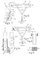
Fig. 1 zeigt einen Teil des Hinterrades 10 eines Fahrrades mit auf einer -- von Speichen 12 gehaltenen -- Felge 14 vorgesehenem Luftreifen 16, der von einem Schutzblech 17 überspannt und dem nahe einer Radgabel 18 eine Felgenbremse 19 zugeordnet ist.1 shows a part of the
Über dem Abschnitt des Schutzbleches 17 ist ein Gepäckträger 20 angeordnet. Dieser besteht i.w. aus einem auf zwei Metallbügeln 22 runden oder rechteckigen Querschnitts festgelegten Deckel 24 sowie einer letzteren zu einem quaderartigen Körper -- in gewähltem Ausführungsbeispiel; einer Gesamtlänge a von 440 mm, einer Höhe h von etwas mehr als 80 mm und einer Breite b von etwa 140 mm -- ergänzenden Wanne 26, die in Fahrtrichtung x am Deckel 24 verschiebbar ist.A
Der Deckel 24 ist ein Werkstoff-Formteil mit einer Auflagefläche 28, von der in Fahrtrichtung x verlaufende Rippen 29 aufragen und die an beiden Enden in pultartig nach außen sowie aufwärts geneigte Endflächen 30, 31 übergeht. Die heckwärtige Endfläche 31 ist Teil eines gewölbten Querwulstes 32, der beispielsweise in Fig. 1 deutlich erkennbar und mit ebenfalls geneigten Unterkanten 33 versehen ist.The
In Draufsicht verjüngt sich der Endwulst 32 -- und mit ihm der Körper des Gepäckträgers 20 -- entsprechend an zwei Heckseitenflächen 34 der Wanne 26 in einem Winkel w von etwa 15°.In plan view, the end bead 32 - and with it the body of the luggage carrier 20 - tapers accordingly on two rear side surfaces 34 of the
Auch der in Fahrtrichtung x vordere Bug 36 des Gepäckträgers 20 verjüngt sich in Draufsicht gemäß Fig. 2 nach vorne hin -- oberhalb entsprechender Bugseitenflächen 37 der Wanne 26 -- in einen Winkel t von etwa 20°.The
An die Pultfläche 30 des Buges 36 schließt eine flache und nach vorn geneigte Frontfläche 38 an, die mit einer nach unten geneigten Bugunterfläche 39 an einen Buggrad 36m stößt. In der Pultfläche 30 sind zwei Schlitze 35 parallel zur Auflagefläche 28 angedeutet, in welche die Enden von Zurriemen 40 eingesetzt sind. Diese verschließen die Schlitze 35 dicht.A flat and forwardly inclined
Die untere -- einen in Fig. 4 deutlich erkennbaren Trennspalt 42 zwischen Deckel 24 und Wanne 26 begrenzende -- Deckelkontur 44 ist unterhalb der Pultfläche 30 bei 45 schulterartig zu einem Anschlag nach unten versetzt (Abschnitt 44m), der die Schubbewegung der Wanne 26 nach vorn begrenzt. Außerdem ist am Bug 36 des Deckels 24 ein Winkeleisen 48 erkennbar, dessen freier Schenkel 49 zum Festlegen an der Radgabel 18 in einem Abstand i von beispielsweise 30 bis 40 mm dient. Im Winkeleisen 48 sind Löcher -- gegebenenfalls auch Langlöcher -- für den Einsatz von Schrauben vorgesehen.The lower - a
Die Wanne 26 ist mit einer in ihrer Innenraum 27 einragenden mittigen Längseinformung 50 ihrer Bodenplatte 25 zur Aufnahme des Fahrradschutzbleches 17 (Fig. 3) ausgestattet sowie an ihren Seitenwänden 52 mit nach innen ragenden Kantennasenleisten 53, welche von an den Deckel 24 angeformten Führungsschienen 54 L-förmigen Querschnittes untergriffen und geführt sind.The
Dieses Führungssystem 53/54 endet am Anschlag 45, von dem aus sich die Seitenwände 52 der Wanne 26 entsprechend der Deckelform bugwärts bis zu der etwa parallel zur Radgabel 18 geneigten Bugunterfläche 39 als die bereits genannten -- und bevorzugt leicht gewölbten -- Bugseitenflächen 37 fortsetzen.This
In der die Wanne 26 nach hinten begrenzenden Heckfläche 56 ist ein verhältnismäßig großflächiger Rückstrahler 57 angebracht sowie über diesem in der vertikalen Achse M ein Zylinderschloß 58, dessen Schlüssel in Fig. 2 mit 59 bezeichnet ist. Ein Schloßriegel 58a greift in Schließstellung in eine aus Gründen der Übersichtlichkeit nicht wiedergegebene Ausnehmung des Deckels 24 blockierend ein. Beidseits des Zylinderschlosses 58 erstreckt sich unterhalb des Querwulstes 36 eine Griffmulde 60 des Deckels 24, eine Griffmulde der Wanne 26 ist bei 61 angedeutet.A relatively large-
Sowohl in der Auflagefläche 28 als auch den Seitenflächen 63 des Deckels 24 sind in einem Abstand f voneinander jeweils zwei -- in Draufsicht etwa T-förmige bzw. schlüssellochartige -- Anschlußlöcher 64 in den Kunststoff des Deckels 24 eingeformt oder -- in Fig. 24 durch einen Metalleinsatz 62 angedeutet -- als Ansatzteile vorgesehen; in den breiten Abschnitt 64b jedes Anschlußloches 64 ist das Riegelende 66 eines seinerseits querschnittlich T-förmigen Anschlußkörpers 67 einsetzbar (Fig. 5), wobei die Länge e des Riegelendes 66 etwa der Höhe jenes breiten Abschnittes 64b entspricht, an den ein enger Schlitzteil 64e jenes Anschlußloches 64 anschließt.Both in the
Nach geringfügigem Verschieben des Anschlußkörpers 67 in Fahrtrichtung x hintergreift dessen breites Riegelende 66 -- beispielsweise das freie Ende einer in ein Paar von Anschlußlöchern 64 gemäß Fig. 6 eingesetzten Tragstange 68 -- die Wände des engen Schlitzteils 64e; dieses ist als hinterschnittene Nut ausgebildet.After the
Wie Fig. 5 erkennen läßt, sind jeweils ein Anschlußloch 64 von Auflagefläche 28 und ein entsprechendes der Seitenfläche 63 einander unter Bildung eines gemeinsamen Aufnahmeraumes 65 für Riegelenden 66 zugeordnet und zwar oberhalb der Führungsschiene 54 in einem breiten Werkstoffstreifen 70 des Deckels 24, an dessen -- die Auflagefläche 28 anbietenden -- Decke 71 Längsrippen 72 stabilisierend angeformt sind.As can be seen in FIG. 5, a
Diese gehen bugwärts in eine kompakte Platte 73 über, an deren bei geschlossenem Gepäckträger 20 nicht zugänglichen Unterseite 74 das Winkeleisen 48 entsprechend Fig. 9 befestigt ist.These pass into the bow into a
Ist die Wanne 26 in ihre beispielsweise in Fig. 6 dargestellte Schließstellung eingeschoben, greift jeweils ein Schließbolzen 69 in jenen Aufnahmeraum 65 ein und endet am Schlitzteil 64e vor einem gegebenenfalls darin ruhenden Riegelzapfen 66 - letzteres ist nun unverrückbar festgelegt; die Entnahme der Anschlußorgane 67 ist nur bei geöffneter Wanne 26 möglich.If the
Jene Schließbolzen 69 können voneinander unabhängig einsetzbar bzw. entfernbar sein, was besondere Handhabungsvorteile bietet. Besonders bevorzugt ist es, die beiden Schließbolzen 69 starr mit der Wanne 26 zu verbinden, so daß sich bei eingeschobener Wanne 26 eine selbsttätige Verriegelung des jeweiligen Anschlußkörpers 67 (Seitentasche, oben aufgesetzter Kindersitz oder dergl.) ergibt. durch Betätigen des Zylinderschlosses 58 kann dann die Wanne 26 in ihrer Einschubstellung (= Schließstellung) sperrend festgelegt werden und damit gleichzeitig auch die Anschlußkörper 67. Nach dem Entriegeln des Zylinderschlosses 58 kann dann die Wanne 26 wahlweise wieder ausgezogen werden mit gleichzeitiger Entriegelung der Anschlußkörper 67. Die Seitentasche 21 bzw. der Kindersitz ist aufgrund der Langloch-Verbindung noch weiterhin am Gepäckträger festgelegt, da zum Entfernen der Seitentasche bzw. des Kindersitzes oder dergl. eine Bewegung in Längsrichtung des jeweiligen schlüssellochartigen Anschlußlochs (hier parallel zur Fahrzeug-Längsrichtung) erforderlich ist mit nachfolgender Aushebe-Bewegung des jeweiligen Anschlußkörpers 67 aus dem Anschlußloch 64. Nachfolgend werden noch an Hand der Figuren 35 und 36 zwei weitere Ausführungsformen der Schließeinrichtung für die Anschlußlöcher 64 erläutert.Those locking
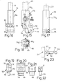
Die Fig. 10, 11 verdeutlichen, daß der Gepäckträger 20 ohne weiteres im Abstand i zur Radgabel 18 (Fig. 10) oder unmittelbar an diese montiert werden kann. Im letztgenannten Fall liegt der lange Schenkel 49 des Winkeleisens 48 der Wanne 26 direkt, also lose, an. Die beiden gebogenen Metallbügel 22 jeder Trägerseite sind im Bereich ihrer aneinanderliegenden Steckenden 23 zusammengeführt sowie durch einen in Seitenansicht L-förmigen Steckschuh 76 zusammengefaßt; letzterer weist ein im Abstand j zur Mittelachse N des Metallbügels 22 exzentrisches Loch 77 auf, dank dessen der Steckschuh 76 mit einer Schraube 78 im Nabenbereich des Fahrrades festgelegt wird. Dieser Abstand j entspricht der Hälfte der Kraglänge i des Winkeleisens 49, was die Montage erheblich vereinfacht. Falls nämlich keine Hinterrad-Felgenbremse 19 (s.Fig. 1) vorgesehen ist (z.B. bei Rücktritt-Fahrradnaben), erfolgt zweckmäßigerweise eine unmittelbare Befestigung des Gepäckträgers 20 am Fahrrad, insbesondere an der sogenannten Pletscher-Platte, im Bereich der Radgabel 18. Bei Verwendung eines abstandsveränderlichen Zwischenstücks, beispielsweise des Winkeleisens 49, wird dieses in seine gepäckträgernahe Stellung gebracht (Fig. 11) und an der Pletscher-Platte fixiert. Der Steckschuh 76 wird dabei in der in Fig. 11 dargestellten Stellung aufgesteckt, also mit gegenüber der Mittelachse N nach hinten versetztem Loch 77.10, 11 illustrate that the
Ist dagegen eine Felgenbremse 19 gemäß Fig. 1 vorgesehen, so muß der Gepäckträger um einen Horizontalabstand i nach rückwärts versetzt am Zweiradfahrzeug montiert werden, damit zwischen Radgabel 18 und eingeschobener Wanne 26 ausreichend Platz für die Felgenbremse 19 ist. Das Winkeleisen 49 wird hierzu in seiner gerade um diesen Abstand i versetzten, gepäckträgerfernen Position am Deckel 24 montiert. Hier wird der Steckschuh 76 in einer um 180° um die Mittelachse N verdrehten Stellung an die Steckenden 23 aufgesteckt (Fig. 10), so daß nunmehr das Loch 77 um den Abstand j vor der Mittelachse N liegt. Gegenüber der Grundfiguration in Fig. 11 ergibt sich eine Verlagerung des Lochs 77 um insgesamt 2j = i in Bezug auf die Mittelachse N. Dies entspricht dem gewünschten Maß.If, on the other hand, a
Der Steckschuh 76 der in Fig. 13, 14 dargestellten Ausführung weist ein Rohrteil 76a rechteckigen Qeurschnittes sowie -- damit einstückig -- eine seitliche Fahne 75 aus Vollmaterial (Kunststoffspritzguß) auf. Mit 80 ist ein ringartiges Einsatzstück aus Metall mit nach innen gerichteten Noppen 81 bezeichnet, die in entsprechende Ausnehmungen 23a der Steckenden 23 einsetzbar sind und deren Längenverstellung ermöglichen. Das Einsatzstück kann, wie in Fig. 14 gezeigt, über das Rohrteil 76a geschoben und dort aufgerastet werden; alternativ hierzu kann das Einsatzstück auch in das Innere des entsprechend überdimensioniert auszubildenden Rohrteils 76 von oben her eingesteckt werden. Zur Längenanpassung (und zum Aufrasten) kann das ringartig geschlossene Einsatzstück 80 entgegen Federkraft in der einen oder anderen Richtung momentan elastisch aufgeweitet werden; das Einsatzstück 80 kann jedoch auch geschlitzt ausgebildet sein, wobei dann entweder ausreichend stark zurückfedernder Federstrahl einzusetzen ist oder durch eine Schraubverbindung oder Schellenanordnung für zuverlässigen Zusammenhalt der Anordnung zu sorgen ist.The plug-in
Bei einer anderen Ausführung sind gemäß Fig. 12 an den Steckenden 23 seitliche Kerben 23b für entsprechend angeordnete Noppen 81 angeordnet.In another embodiment, according to FIG. 12,
Ein anderer Schuh 76 ist gemäß Fig. 15 bis 18 mit einem oberhalb des Loches 77 eingeformten Anschlußauge 82 für eine nicht erkennbare Schutzblechstrebe versehen; leztere wird mittels einer ein Querloch 83a anbietenden Spezialschraube 83 festgelegt. Statt der Ausnehmungen 23a ist hier im Steckende 23 ein Langloch 84 vorhanden, das von einer -- auch den Rohrteil 76a durchsetzenden -- Stellschraube 85 im Bereich eines gezahnten Druckeinsatzes 86 aus Stahl durchgriffen wird. Der Druckeinsatz 86 bzw. dessen Zähne 86a schneidet/schneiden sich in den weicheren Werkstoff, bevorzugt eine Leichtmetallegierung, des Metallbügels 22 ein, und zwar in beliebiger Längenposition der Steckenden 23. Dies ermöglicht bei baulich geringem Aufwand eine einfache und schnell durchzuführende stufenlose Höheneinstellung des Gepäckträgers.Another
Beispiele für Anschlußorgane zeigen die Figuren 19 ff. Im Gegensatz zu den bereits beschriebenen Enden der Tragstange 68 für eine seitliche Packtasche 21 od.dgl., kann letztere auch unmittelbar mit einem Paar gesonderter Gußkörper 90 als Anschlußorgane ausgerüstet sein, die im Abstand f der Packtasche 21 od.dgl. festgelegt sind. Dieser Gußkörper 90 besteht aus dem Anschlußorgan 76 mit Riegelzapfen 66, einem anschließenden Sockelstück 89 und einem mittels einer Achse 91 angelenkten Befestigungsteil 92, das mit der Packtasche 21 od. dgl. verbunden wird.Examples of connecting elements are shown in FIGS. 19 ff. In contrast to the ends of the
Der Gußkörper 90 ist länglich und flach dargestellt, kann aber auch runden Querschnitt besitzen. Er wird mittels Schrauben beispielsweise so an der Packtasche 21 oder einem entsprechenden Zusatzteil festgelegt, daß der schwenkbare Riegelzapfen 66 in eine der beschriebenen Anschlußlöcher 64 eingesetzt zu werden vermag.The
Bei nicht wiedergegebenen Ausführungen kann das Sockelstück als Gewindezapfen ausgebildet und an dem Zusatzteil angeschraubt werden. Auch ist vorgesehen, die Riegelzapfen 66 an das Ende eines in Fig. 24 bei 89a angedeuteten Verlängerungsarmes anzuordnen.In versions not shown, the base piece can be designed as a threaded pin and screwed onto the additional part. Provision is also made to arrange the locking pins 66 at the end of an extension arm indicated at 89 a in FIG. 24.
Beim Ausführungsbeispiel der Fig. 24 ist sowohl am Querwulst 32 als auch im Bereich der Pultfläche 30 eine angeformte Eingriffleiste 46 zu erkennen. Statt des Winkeleisens 48 erfolgt hier die bugseitige Festlegung mittels eines einerseits in den Deckel 24 eingesetzten Winkelbügels 48a. Die Steckenden 23 der Metallbügel 22 -- die in Sonderfällen auch am Kunststoff geformt sein können -- sind in bereits beschriebener Weise mit seitlichen Außenrillen 23b ausgestattet. Der entsprechende schuh 76b nimmt die Steckenden 23 in seinem seitlich offenen Innenraum 79b auf, der dann mittels eines Schubdeckels 79 verschlossen wird.In the embodiment of FIG. 24, an integrally formed
In Fig. 25 sind an den Steckenden 23 Innenrillen 23i zur Aufnahme einer Schraube 78i vorgesehen, die mit ihrem freien Ende an der Radgabel 18 od.dgl. festliegt und zudem eine die Steckenden 23 lösbar verbindende Auflageklammer 78k hält.25,
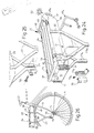
Der Gepäckträger 20 ist auch zur Festlegung an einem Vorderrad 11 bzw. an der Lenkergabel 13 eines Fahrrades od. dgl. geeignet und nimmt in diesem Fall statt des Rückstrahlers 57 einen Scheinwerfer 55 auf, dessen Elektroanschlüsse in der Zeichnung vernachlässigt sind (Fig. 26). Die Metallbügel 22 sind mit einer Steckschuhfahne 75 an die Radnabe 15 angeschlossen.The
Sowohl bei der letztbeschriebenen Version als auch bei heckwärtigem Gepäckträger 20 können Blinkleuchten 51 vorgesehen werden, die in Fig. 24 dargestellt sind. Die gegebenenfalls dafür sowie für eine Verwendung als Standlicht erforderliche Elektronik kann problemlos im Deckel 24 untergebracht werden.Indicator lights 51, which are shown in FIG. 24, can be provided both in the last-described version and in the
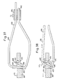
Zum lösbaren Festlegen der als Gummibänder ausgebildeten und an der Pultfläche 30 gehaltenen Zurriemen 40 ist am Querwulst 32 ein Griffstück 87 angeordnet mit Querstegen 87a für die Zurriemen 40. Dieses Griffstück 87 hintergreift mit Gegenhaken 88 die Unterkante 32a jenes Querwulstes 32 und ist davon leicht trennbar, so daß auch aufliegende Lasten 91a größeren Umfanges problemlos festgezurrt werden können (Fig. 32). Eine Gegenzahnung 92a an den einander zugekehrten Zurriemenflächen erleichtert die Längsverstellung der Zurriemen 40.For releasable fixing of the lashing straps 40 designed as rubber bands and held on the
Eine einfachere Ausgestaltung des Griffstückes ist in Fig. 30, 31 mit 87n bezeichnet, ein aus Draht gebogener Federbügel 93 bietet sowohl die Querstege 87a an als auch die Gegenhaken 88.A simpler embodiment of the handle is designated by 87 n in FIGS. 30, 31, a
Fig. 33 zeigt eine weitere Ausführungsform 120 des Gepäckträgers, wobei Bauelemente, die ihrer Funktion nach solchen in den vorhergehenden Figuren entsprechen, mit denselben Bezugsziffern, jeweils vermehrt um die Zahl 100, versehen sind.FIG. 33 shows a
Man erkennt die Wanne 126, an deren in Fig. 33 erkennbaren rückwertigen Ende der Rückstrahler 157 (oder ein Rücklicht bzw. ein Scheinwerfer bei Montage des Gepäckträgers am Vorderrad) anzubringen ist. Wie in Fig. 24 angedeutet, kann an der in Fig. 33 mit 200 bezeichneten, schräg nach hinten und innen verlaufenden Seitenfläche eine von zwei Blinkleuchten angebracht werden. Das Zylinderschloß 158 ist beim Zusammenbau mit einem innerhalb der Wanne 126 angedeuteten Schwenkriegel 202 mittels Splint 204 zu verbinden.One recognizes the
Der Deckel 124 ist mit den insgesamt vier Paaren aus jeweils zwei Anschlußlöchern 164 versehen, wobei die beiden hinteren Paare durch jeweils ein einzelnes Schließteil 206 einer im folgenden an Hand der Fig. 35 noch näher zu erläuternden Schließeinrichtung 210 wahlweise absperrbar sind. Bei Zusatzeinrichtungen, wie Seitentaschen 21 oder Kindersitzen, die sowohl vordere als auch hintere Anschlußlöcher 164 benutzen, genügt es, beispielsweise die hinteren Anschlußlöcher mit dieser Sperreinrichtung zu versehen, da diese Zusatzeinrichtungen von vorneherein ausreichend biegesteif ausgebildet sind, so daß dasjeweilige Anschlußteil aus dem nicht gesicherten Anschlußloch nicht herausgehoben werden kann; alternativ oder zusätzlich können die entsprechenden Anschlußstücke auch gemäß Fig. 6 mit einem gesonderten steifen Bügel 68 miteinander verbunden sein.The
Die beiden gebogenen Metallbügel 122 der beiden seitlichen Gestänge sind mit einem oberen, horizontal abgewinkelten Endstück 212 ausgebildet, mit welchem sie, nach Einstecken in ein entsprechendes Loch 164 am heruntergebogenen Seitenrand 216 des Deckels 124, mit diesem mittels Schrauben 214 festgeschraubt sind.The two
Die unteren Steckenden 123 beider Metallbügel 122 sind, aneinandergelegt, in die Stecköffnung 218 des jeweiligen Steckschuhs 176 eingesteckt. Aufgrund des Langlochs 184 am Steckende 123 ergibt sich die Möglichkeit einer stufenlosen Höhenjustierung. Die in das Langloch 184 eingreifende Stellschraube 185 preßt beidseits an die Einsteckenden jeweils eine Zahnscheibe 223 (ähnlicher Aufbau wie in den Figuren 16 - 18), um in der gewählten Höhenposition eine zuverlässige Formschlußverbindung zu erreichen. Entsprechend Figuren 10 und 11 ist der Steckschuh 176 wahlweise in einer der beiden möglichen Orientierungen an den Metallbügeln 122 anbringbar. Zur Feinanpassung ist der Steckfuß mit einem horizontal verlaufenden Langloch 240 ausgebildet zur Aufnahme einer der Befestigung am Zweiradrahmen dienenden Schraube 242 (z.B. Radachse).The lower plug ends 123 of both
Zum Anschluß des vorderen Endes des Deckels 124 an der Hinterradgabel oder an der Pletscher-Platte bestehen eine Reihe weitere Möglichkeiten (an Stelle des Winkels 48 gemäß Figuren 9 und 10). In Fig. 33 recht oben erkennt man eine einfache Verbindungsplatte 220 zur unmittelbaren Montage an der Pletscher-Platte über nicht dargestellte Befestigungsschrauben, die in die beiden Langlöcher 222 der Platte 220 eingreifen. Entsprechende Befestigungsschrauben sind in die beiden oberen Löcher 224 einzustecken und mit dem Deckel 124 zu verschrauben. Im Falle der Verwendung einer Hinterrad-Felgenbremse wird an Stelle der Platte 220 ein Winkel 226 verwendet, der dementsprechend mit Langlöchern und Rundlöchern für die genannten Befestigungsschrauben ausgebildet ist sowie zusätzlich mit einer Ausnehmung 228 im oberen Schenkel zum Durchtritt des Seilzugs für die Felgenbremse.There are a number of other possibilities for connecting the front end of the
Alternative hierzu können auch Abstandshülsen 230 eingesetzt werden, die von dementsprechend langen Befestigungsschrauben 232 durchsetzt werden. In Fig. 33 sind ferner zwei kurze Befestigungsschrauben 234 abgebildet für den Fall der unmittelbaren Montage am Zweiradrahmen ohne Hinterrad-Felgenbremse.As an alternative to this,
In einer weiteren Befestigungsart wird der Deckel 124 über entsprechende Schellen 236 unmittelbar an den beiden Rohren der hinteren Radgabel festgelgt.In a further type of fastening, the
In Fig. 33 ist unterhalb des Deckels 124 an dessem rechten Ende ein Metall-U-Profil 238 angedeutet, welches an der Deckelinnenseite angebracht ist und als Widerlager für die Befestigungsschrauben (z.B. 232,234) dient. Dies entlastet den beispielsweise aus Kunststoff bestehenden Deckel 124 Daneben ist ferner erkennbar ein Anschlußkörper 167, der entsprechend dem Anschlußkörper 67 gemäß Figuren 5 bis 7, 22 und 23 Teil einer Seitentasche oder dergl. sein kann und über die schlüssellochartigen Anschlußlöcher 164 am Deckel 124 sperrend festgelegt werden kann.In Fig. 33, a
Ferner erkennt man in Fig. 33 oben ein Gummiband (Zurrstrang) 140, welches durch zwei Schlitze 231 in der nach vorne und oben ansteigenden pultartigen Fläche 130 vom vorderen Ende des Deckels 124 geführt ist, so daß er dort zwischen den Löchern 231 entlang der Innenseite des Deckels 124 verläuft und so am Deckel festgelegt ist. Die beiden freien Enden des Zurrstrangs 140 sind mehrfach auf das Griffstück 187 aufgewickelt mit Festlegung des äußersten Zurrstrangendes jeweils in einem Schlitz 233. Die mehrfachen Lagen der Aufwicklung durchsetzen jeweils eine rechteckige Durchtrittsöffnung 235 im Griffstück, die an ihrem hinteren Rand jeweils einen seitlich offenen Schlitz 237 aufweist. Dieser ermöglicht es, eine oder mehrere Lagen der Wicklung nacheinander abzuwickeln bzw. weitere Lagen aufzuwickeln, um auf diese Weise die effektive Länge des Gummibands (Zurrstrang) 140 wahlweise zu verändern. Auf diese Weise können auch große Gegenstände ohne allzu große Zugkraft am Gepäckträger 120 festgelegt werden.33, a rubber band (lashing cord) 140 can be seen at the top, which is guided through two
Wie insbesondere Fig. 34 zeigt, ist die Wanne 126 über eine Profilschiene 201 am Deckel 124 verschiebbar gelagert. Die Profilschiene 201 entspricht im Querschnitt einem Doppel-C-Profil, in deren obere Profilhälfte der entsprechend ausgebildete Umfangsrand 203 des Deckels 124 formschlüssig eingesteckt ist. Wie Fig. 33 zeigt läuft die Profilschiene 201 entlang des gesamten Außenumfangs des Deckels 124. Sie sorgt auf diese Weise für mechanische Verstärkung des von einem Kunststoffteil gebildeten Deckels 124 bei ansprechendem Äußeren. Zur sicheren Übertragung der Kräfte vom Deckel 124 auf das Gestänge sind die Metallbügel 122 unmittelbar mit der Profilschiene 201 verkoppelt, insbesondere mittels in Fig. 33 angedeuteter Gewindebolzen 205, die nach außen hin praktisch unsichtbar knapp unterhalb des abgewinkelten Endstücks 212 parallel zu diesem am anschließenden Vertikalschenkel 207 des jeweiligen Metallbügels 122 festgeschweißt sind und nach dem Zusammenbau ein entsprechendes Loch 209 in der Profilschiene 201 durchsetzen und über anschließend aufgeschraubte Schraubmuttern 211 starr mit der Profilschiene 201 verbunden sind.As shown in FIG. 34 in particular, the
Die untere Hälfte des Doppel-C-Profils dient im Bereich der beiden einander gegenüberliegenden, zur Fahrtrichtung parallelen Längsseitenabschnitte 213 der Profilschiene 201 der Führung des entsprechend geformten Wannenrandes 215 der Wanne 126. Zum Herausleiten bzw. Hineinleiten des Wannenrands 215 ist am hinteren Ende des jeweiligen Längsseitenabschnitts 213 eine das untere C-Profil fortsetzende Ausfräsung 217 ausgebildet. In diesem Bereich schließt sich an den horizontal verlaufenen Längsseitenabschnitt 213 ein kurzer, nach oben und hinten geneigter Abschnitt 219 der Profilschiene 201 an, der dann in den zur Fahrtrichtung senkrechten und horizontal verlaufenden Hinterrandabschnitt 221 der Profilschiene 201 übergeht.The lower half of the double-C profile is used in the region of the two opposite
In einer weiteren, in Fig. 33 lediglich mit unterbrochener Umrißlinie angedeuteten Ausführungsform der Erfindung, ist an beiden Längsseiten des Gepäckträgers 210 jeweils eine Führungsschiene 301 vorgesehen, an welcher sowohl der Deckel 124 als auch die Wanne 126 längsverschiebbar geführt sind. Dies ermöglicht einen teleskopartigen Auszug der Wanne. In Fig. 33 ist mit strichlierter Umrißlinie die Position 301′ der Führungsschiene 301 bei eingeschobener Wanne angedeutet und mit einer Strich-Punkt-Linie der Position 301′′ bei in ihre äußerste Auszugsstellung 126′′ ausgefahrener Wanne 126. Entsprechende Bewegungsanschläge sorgen dafür, daß die Wanne sowie die Führungsschienen 301 nicht weiter ausgezogen werden können.In a further embodiment of the invention, indicated only with a broken outline in FIG. 33, a
Gemäß Fig. 34A kann die Wanne 126 an ihrer Innenseite 126a mit einer Winkelprofilschiene 500 versehen sein, deren oberer Schenkel 502 nach innen absteht. Die Schiene 500 erstreckt sich lediglich entlang der beiden Wannenlängsränder und sorgt hier für eine Aussteifung der Wanne. Der Schenkel 502 wird von einem dementsprechend nach außen gerichteten Schenkel 504 einer Winkelprofil-Gegenschiene 506 untergriffen. Die im Querschnitt Z-förmige Schiene 506 ist an der Unterseite des Deckels 124 angebracht. Die Schiene 500 hat im wesentlichen L-Profilquerschnitt.According to FIG. 34A, the
Die Schiene 506 kann mit dem Deckel verschraubt sein, was durch eine unterbrochene Linie 508 angedeutet ist. Der Vertikalschenkel 510 der Schiene 500 kann in nicht dargestellter Weise mit nach unten abstehenden Zacken ausgebildet sein, um den Zusammenhalt der an die Wanneninnenseite bei der Fertigung eingepreßten Schiene 500 mit dem Wannenkorpus zu verbessern. Bei dieser Ausführungsform entfällt die umlaufende Profilschiene 201.The
Fig. 35 zeigt die Schließeinrichtung 210 an der Unterseite des Deckels 124 mit näheren Details. Man erkennt einen Federbügel 240 in Form einer geschlossenen Schleife. Zwei relativ kurze, zur Ausschubrichtung A der Wanne 128 parallel verlaufende, einander in gleicher Höhe gegenüberliegende Seitenschenkel 242 sind jeweils mit einem der beiden schieberartigen Schließteile 206 bewegungsverkoppelt, und zwar dadurch, daß diese beiden Seitenschenkel 242 jeweils ein entsprechendes Loch 244 des Schließteils 206 durchsetzen. Die beiden Schließteile 206 sind in nicht näher dargestellter Weise linear geführt mit Bewegungsrichtung B parallel zur Deckelebene und senkrecht zur Ausschubrichtung A der Wanne 128.35 shows the
Der in Bezug auf die Ausschubrichtung A hintere (in Bezug auf die Fahrtrichtung vordere), die beiden Seitenschenkel 242 verbindende Verbindungsschenkel 246 ist im Bereich seiner Längenmitte U-förmig abgewinkelt (Abschnitt 248) und mit diesem Abschnitt an der Deckelunterseite in nicht näher dargestellter Weise festgelegt (z.B. festgeschraubt). Von diesem Abschnitt 248 laufen jeweils nach vorne (in Fahrtrichtung) und außen geneigte Abschnitte 250 zu den beiden Seitenschenkeln 244. Der andere (vordere) Verbindungsschenkel 250 weist im Bereich seiner Längenmitte eine Bügelschlaufe 252 auf, die ein zur Bewegungsrichtung A paralleles Langloch 254 bildet. In dieses Langloch 254 greift ein am Deckel 124 befestigter Führungsbolzen (Kopfschraube) 256 ein, um auf diese Weise den vorderen Verbindungsschenkel 250 sicher an der Deckelunterseite mit Bewegungsspiel parallel zur Richtung A festzulegen. Von der Federbügelschlaufe 252 laufen wiederum nach außen und hinten geneigte horizontale Abschnitte 258 zu den beiden Seitenschenkeln 242. Die Abschnitte 250 und 248 bilden demnach angenähert eine Raute.The connecting
Der Federbügel 240 nimmt ohne äußere Krafteinwirkung die in Fig. 35 strichliert angedeutete Form ein. Diese definiert die Öffnungsstellung der Schließeinrichtung 210, in welcher die beiden Schließteile 206 nach innen zurückgezogen sind (strichlierte Stellung 206′). In dieser Stellung sind sie aus dem Aufnahmeraum 260 innerhalb des Deckels 124 und unterhalb des jeweiligen Anschlußlochpaares herausgerückt. Es besteht daher die Möglichkeit, einen in Fig. 35 unten angedeuteten Anschlußkörper 167 aus dem Bereich des engen Lochabschnitts 262 heraus in den Bereich des weiten Lochabschnitts 264 zu verschieben (in Richtung A) und anschließend den innerhalb des Aufnahmeraums 260 befindlichen Kopf 266 durch den weiten Lochabschnitt 264 hindurch herauszuziehen. Wie auch Fig. 33 zeigt, sitzt der Kopf 266 an einem Hals 268. Die Kopfdicke (in Richtung B) entspricht im wesentlichen der gleich orientierten Weite des weiten Lochabschnitts 264; die gleich orientierte Dicke des Halses 268 entspricht im wesentlichen der gleich orientierten Weite des engen Lochabschnitts 262, woraus sich die gewünschte Schlüssel-Verbindungsart ergibt.The
Wird nun die Wanne 128 eingeschoben, so schlägt kurz vor Erreichen der Einschubstellung die Wanne (mit ihrer schloßseitigen Rückwand 270) am Federbügel 246 an (im Bereich der Federbügelschlaufe 252). Bei weiterem Einschub wird der Federbügel zunehmend derart verformt, daß sich die beiden Verbindungsschenkel zunehmend einander nähern und in der Folge die beiden Seitenschenkel 242 zunehmend sich voneinander entfernen. Dementsprechend werden auch die beiden Schließteile 206 zunehmend nach außen in den jeweiligen Aufnahmeraum 260 geschoben, bis sie schließlich in Fig. 35 die mit durchgezogener Linie gezeigte Stellung einnehmen (Schließstellung der Schließeinrichtung 210 bei eingeschobener Wanne). Hierbei ergibt sich zwangsläufig eine gewisse Verschiebung der beiden Seitenschenkel 242 innerhalb der Durchgangslöcher 244 in den Schließteilen 206.If the tub 128 is now pushed in, the tub strikes (with its
In besagter Stellung befinden sich die äußeren Enden der beiden Schließteile 206 im Bereich des dem engen Lochabschnitt 262 nächstgelegenen Endes des weiten Lochabschnitts 264 und verhindern so ein Lösen der Schlüssellochverbindung durch Verschieben des Anschlußkörpers aus dem engen Lochabschnitt zum weiten Lochabschnitt.In said position, the outer ends of the two locking
In Fig. 35A ist eine weitere, mit 610 bezeichnete Ausführungsform der Schließeinrichtung in explosionsartiger Darstellung angegeben. Man erkennt hier wiederum die beiden Schließteile 606, die in nicht näher dargestellter Weise an der Deckelunterseite in Richtung B verschiebbar gelagert sind. An ihrem inneren Ende greifen beide Schließteile 606 über einen nach unten abstehenden Vorsprung 612 jeweils in ein Langloch 614 eines als Kraftübertragungsteil dienenden Blechstanzteils 616 ein. Das Blechstanzteil 616 ist in nicht näher dargestellter Weise an der Deckelunterseite in Richtung A verschiebbar gelagert. Beide Langlöcher 614 laufen in Richtung A voneinander weg schräg nach außen. Falls im Laufe der Einschubbewegung der Wanne diese an das in Fig. 35A linke, nach unten abgewinkelte Ende 618 des Blechstanzteils 616 anschlägt, wird dieses aus der in Fig. 35A dargestellten Öffnungsposition nach rechts verschoben. Hierbei bewegen sich die beiden Schließteile 606 zwangsläufig nach außen in ihre jeweilige Schließstellung. Dies geschieht entgegen der Vorspannkraft einer die beiden inneren Enden der beiden Schließteile miteinander verbindenden Vorspannfeder 620. Beim Ausziehen der Schublade sorgt die Vorspannfeder 620 dafür, daß die beiden Schließteile 606 nach innen in ihre Freigabestellung zurückgezogen werden, wobei sich das Blechstanzteil dementsprechend in Fig. 35A nach links bewegt.35A shows a further embodiment of the locking device, designated 610, in an exploded view. Here again one can see the two closing
Um die Anschlußlöcher (z.b. 164 in Fig. 35) wasserdicht abzuschließen, können am Deckel 4 nicht dargestellte Verschlußdeckel angebracht sein, insbesondere durch Einsatz des Ultraschall-Schweißverfahrens.In order to seal the connection holes (e.g. 164 in FIG. 35) in a watertight manner, closure covers (not shown) can be attached to the cover 4, in particular by using the ultrasonic welding method.
Fig. 36 zeigt eine alternative, mit 310 bezeichnete Ausführungsform der Schließeinrichtung. Hier ist ein an der Deckelunterseite um eine Achse 312 schwenkbar gelagerter Doppelarmhebel 314 vorgesehen, dessen in Fig. 36 linker Arm hakenförmig gekrümmt und als Schließteil 306 dient. Der andere Arm 316 dient der Bewegungssteuerung. Auch hier geschieht dies durch Anschlag der Wanne, insbesondere der Wannenrückwand 270 am Ende der Einschubbewegung, so daß der Doppelarmhebel 314 aus seiner in Fig. 36 wiederum strichliert angedeuteten Ausgangsstellung 314′ (in die er in nicht näher dargestellter Weise federvorgespannt ist) in die mit ausgezogener Linie dargestellte, der Schließstellung der Schließeinrichtung 310 entsprechende Drehstellung verschwenkt wird. In letzterer Stellung durchsetzt das Schließteil 306 (Hakenende) wiederum den Aufnahmeraum 260 derart, daß ein sich im engen Lochabschnitt befindlicher Anschlußkörper (nicht dargestellt) nicht in den weiten Lochabschnitt 264 verschoben werden kann. In der Ausgangsstellung dagegen ist das Schließteil 306 aus dem Aufnahmeraum 260 herausgezogen.36 shows an alternative embodiment of the locking device, designated 310. Here, a double-
Die Figuren 37 und 38 zeigen eine weitere Art der Ausbildung von Zurrstrang 340 und Griffstück 387 mit der Möglichkeit einer einfachen und schnellen Veränderung der effektiven Zurrstranglänge (zwischen dem Befestigungspunkt am nicht dargestellten Deckel und dem Griffstück 387).Figures 37 and 38 show another type of
In der in Fig. 37 dargestellten Situation ist der Zurrstrang 340 relativ locker durch einen Schlitz 390 des Griffstücks 387 geführt und mit seinem freien Ende 392 über ein Verschiebeteil 394 festgelegt. Das Verschiebeteil 294 kann zur gewünschten Längenanpassung frei in Richtung des Doppelpfeils D entlang des Strangabschnitts 396 zwischen Deckel und Griffstück 387 geschoben werden. Dies ermöglicht fast eine Verdoppelung der ungedehnten Länge des Abschnitts 296.In the situation shown in FIG. 37, the
Wird bei der jeweils gewählten Längeneinstellung Zug auf den Abschnitt 340 ausgeübt (indem an dem Griffstück 387 dementsprechend gezogen wird, z.B. um einen Gegenstand auf den Gepäckträger zu fixieren), so ergibt sich eine Art Selbsthemmung im Schlitz 390 für den Zurrstrang 340. Diese Selbsthemmung wird dadurch erreicht, daß der dem deckelseitigen Zurrstrangende näher gelegene Längsrand 398 des Schlitzes 390 von einer Klemmkante eines Klemmhebels 400 gebildet wird, der unter der Einwirkung der Zugkraft des Abschnitts 396 in Richtung zum gegenüberliegenden Längsrand 402 des Schlitzes 390 gedrückt wird.If tension is exerted on the
Im dargestellten Ausführungsbeispiel ist der Klemmhebel 400 einstückig mit dem Griffstück 387 über eine filmscharnierähnliche Materialverengungsstelle 404 verbunden. Diese ermöglicht die gewünschte Schwenkbewegung des Schwenkhebels 400. Der Schwenkhebel 400 ist doppelarmähnlich ausgebildet, wobei der eine Arm schräg nach unten (in Richtung zum Deckel) und hin zum freien Griffende gerichtet ist und in die Klemmkante 398 ausläuft; der andere Arm verläuft in entgegengesetzter Richtung nach oben und ragt über die Oberseite 410 des Griffstücks 387 hinaus. Der über den Klemmhebel 400 geführte Zurrstrangabschnitt 296 versucht daher bei entsprechender Zugspannung den oberen Arm 412 des Doppelarmhebels 400 in Fig. 38 nach rechts zu verschwenken, woraus sich die gewünschte Kippbewegung um die Materialverengungsstelle 404 (Richtungspfeile 414) ergibt.In the exemplary embodiment shown, the clamping
Die Erfindung, wie vorgehend beschrieben, kann wie folgt zusammengefaßt werden:
Ein Gepäckträger für Zweiradfahrzeuge mit an einer Auflagefläche vorgesehenem und zu wenigstens einem Festpunkt am Zweiradfahrzeug verlaufendem Gestänge sowie mit unter der Auflagefläche an Gleitbahnen angeordnetem und in Längsrichtung daran verschieblichem Schubkasten besteht aus einem am Gestänge festliegenden und die Auflagefläche mit zumindest einer pultartigen Schmalseite anbietenden Deckel sowie aus einer, an dessen Unterfläche in Führungsschienen angebrachten Wanne als Schublade. Am Deckel ist über wenigstens ein schlüssellochartiges Anschlußloch eine Zusatzeinrichtung, insbesondere Seitentasche, Kindersitz oder dergl., lösbar anbringbar über jeweils einen an der Zusatzeinrichtung angebrachten Anschlußkörper. Eine Schließeinrichtung zum Festlegen des Anschlußkopfes am Deckel ist mit der Wanne derart verkoppelt, daß die Wanne bei Übergang in ihre Einschubstellung die Schließeinrichtung in ihre Schließstellung bewegt.The invention as described above can be summarized as follows:
A luggage rack for two-wheeled vehicles with a linkage provided on a support surface and extending to at least one fixed point on the two-wheeled vehicle, and with a drawer arranged under the support surface on slideways and displaceable in the longitudinal direction thereon, consists of a cover fixed to the linkage and offering the support surface with at least one desk-like narrow side and one, on the lower surface of which there is a tub attached as a drawer in guide rails. On at least one keyhole-like connection hole, an additional device, in particular a side pocket, child seat or the like, can be detachably attached to the cover by means of a connector body attached to the additional device. A locking device for fixing the connection head on the cover is coupled to the trough in such a way that the trough moves the locking device into its closed position upon transition into its insertion position.
Claims (53)
dadurch gekennzeichnet,
daß der Gepäckträger (20) aus einem am Gestänge (22) festliegenden und die Auflagefläche (28) mit zumindest einer pultartigen Schmalseite (30, 32) anbietenden Deckel sowie einer an dessen Unterfläche in Führungsschienen (54) angebrachten Wanne (26) als Schublade besteht, die in Schließlage zumindest einem Anschlag (45, 33) des Deckels anliegt und mit diesem einen schachtelartigen Körper bildet, wobei die Wanne ein Schließelement (58) aufweist, welches in Schließlage am Deckel verriegelbar ist.1.Luggage rack for two-wheeled vehicles with a linkage provided on a support surface and extending to at least one fixed point on the two-wheeled vehicle, and with a drawer arranged underneath the support surface on slideways and displaceable in the longitudinal direction thereon, in particular with a drawer which has a longitudinal indentation in the floor for receiving a section of a mudguard oddlg. having,
characterized,
that the luggage carrier (20) consists of a fixed to the linkage (22) and the support surface (28) with at least one desk-like narrow side (30, 32) and a cover (26) attached to the undersurface in guide rails (54) as a drawer which bears at least one stop (45, 33) of the lid in the closed position and forms a box-like body with it, the trough having a closing element (58) which can be locked on the lid in the closed position.
- einen sich am Zweiradfahrzeug, vorzugsweise über ein Gestänge, abstützenden Deckel (Gepäckträgerplatte) (24;124)), dessen Oberseite mit einer Auflagefläche (28) zur Aufnahme von Lasten ausgebildet ist,
- eine an dem Deckel (24;124) schubladenartig geführte Wanne (26;126),
- wenigstens ein Schlüssellochartiges Anschlußloch (64;164) im Deckel (24;124) zur lösbaren Anbringung einer Zusatzeinrichtung, insbesondere Seitentasche, Kindersitz oder dergl., über jeweils einen an der Zusatzeinrichtung angebrachten Anschlußkörper (67;167),
- eine Schließeinrichtung (210) für jedes Anschlußloch (64;164) mit einem Schließteil (69;206), welches in einer Öffnungsstellung der Schließeinrichtung (210) den weiten Lochabschnitt (264) des Anschlußloches (64;164) freigibt zum Einsetzen bzw. Herausnehmen eines Anschlußkopfes (266) des Anschlußkörpers (67;167) in einen bzw. aus dem Aufnahmeraum (260) des Deckels unterhalb des Anschlußloches, und welches in einer Schließstellung der Schließeinrichtung (210;310) in den Aufnahmeraum (260) einrückt zur Festlegung des Anschlußkör pers (67;167) im engen Lochabschnitt (262) des Anschlußloches (64;164),
- ein Schließelement, insbesondere Zylinderschloß, (58;158) zur sperrenden Festlegung der Wanne (26;126) in einer Einschubstellung am Deckel (24;124) und zur sperrenden Festlegung der Schließeinrichtung in ihrer Schließstellung,
dadurch gekennzeichnet,
daß die Wanne (26;126) mit der Schließeinrichtung (210;310) derart verkoppelt ist, daß die Wanne (26;126) bei Übergang in ihre Einschubstellung die Schließeinrichtung (210;310) in ihre Schließstellung bewegt.35. luggage rack for two-wheeled vehicles, in particular according to at least one of the preceding claims or the preamble of claim 1, comprising
a cover (luggage carrier plate) (24; 124)) which is supported on the two-wheeled vehicle, preferably via a linkage, the upper side of which is formed with a support surface (28) for receiving loads,
- a trough (26; 126) guided in a drawer-like manner on the cover (24; 124),
- At least one keyhole-like connection hole (64; 164) in the cover (24; 124) for releasably attaching an additional device, in particular a side pocket, child seat or the like, via a respective connector body (67; 167) attached to the additional device,
- A locking device (210) for each connection hole (64; 164) with a locking part (69; 206), which in an open position of the locking device (210) releases the wide hole section (264) of the connection hole (64; 164) for insertion or Removing a connection head (266) of the connection body (67; 167) into or out of the receiving space (260) of the cover below the connection hole, and which in a closed position of the locking device (210; 310) engages in the receiving space (260) for fixing the connector body pers (67; 167) in the narrow hole section (262) of the connection hole (64; 164),
a locking element, in particular a cylinder lock (58; 158) for locking the trough (26; 126) in a retracted position on the cover (24; 124) and for locking the locking device in its closed position,
characterized,
that the trough (26; 126) is coupled to the closing device (210; 310) in such a way that the trough (26; 126) moves the closing device (210; 310) into its closed position upon transition into its insertion position.
- einen sich am Zweiradfahrzeug, vorzugweise über ein Gestänge abstützenden Deckel (Gepäckträgerplatte) (24;124), dessen Oberseite mit einer Auflagefläche (28) zur Aufnahme von Lasten ausgebildet ist,
- eine an dem Deckel (24;124) über Führungsschienen schubladenartig geführte Wanne (126),
dadurch gekennzeichnet,
daß längs des Deckelrandes in vorzugsweise geschlossener Schleife eine gesonderte Profilschiene (201) verläuft, und daß die zur Bewegungsrichtung der Wanne (126) parallelen Längsseiten-Abschnitte (213) der Profilschiene (201) als Führungsschiene für einen Rand (215) der Wanne (126) ausgebildet sind.41. luggage rack for two-wheeled vehicles, in particular according to at least one of the preceding claims or the preamble of claim 1, comprising
a cover (luggage carrier plate) (24; 124), which is supported on the two-wheeled vehicle, preferably via a linkage, the upper side of which is formed with a bearing surface (28) for receiving loads,
- a trough (126) guided in a drawer-like manner on the cover (24; 124) via guide rails,
characterized,
that a separate profile rail (201) runs along the edge of the lid in a preferably closed loop, and that the longitudinal side sections (213) of the profile rail (201) parallel to the direction of movement of the trough (126) act as a guide rail for an edge (215) of the trough (126 ) are trained.
- einen sich am Zweiradfahrzeug, vorzugsweise über ein Gestänge abstützenden Deckel (Gepäckträgerplatte) (24;124), dessen Oberseite mit einer Auflagefläche (28) zur Aufnahme von Lasten ausgebildet ist,
- eine an dem Deckel (24;124) über Führungsschienen schubladenartig geführte Wanne,
dadurch gekennzeichnet,
daß an beiden zur Bewegungsrichtung der Wanne (126) parallelen Seiten des Gepäckträgers (120) jeweils eine Führungsschiene (301) vorgesehen ist, an welcher sowohl der Deckel (124) als auch die Wanne (126) längsverschiebbar geführt ist zum teleskopartigen Auszug der Wanne (126).43. luggage rack for two-wheeled vehicles, in particular according to at least one of the preceding claims or the preamble of claim 1, comprising
a cover (luggage carrier plate) (24; 124), which is supported on the two-wheeled vehicle, preferably via a linkage, the upper side of which is formed with a bearing surface (28) for receiving loads,
a trough guided in drawer-like manner on the cover (24; 124) via guide rails,
characterized,
that a guide rail (301) is provided on both sides of the luggage carrier (120) parallel to the direction of movement of the tub (126), on which both the cover (124) and the tub (126) are guided so as to be longitudinally displaceable for the telescopic pull-out of the tub ( 126).
- einen sich am Zweiradfahrzeug, vorzugsweise über ein Gestänge abstützenden Deckel (124) (Gepäckträgerwanne), dessen Oberseite mit einer Auflagefläche zur Aufnahme von Lasten ausgebildet ist,
- eine an dem Deckel (124) schubladenartig geführte Wanne (126),
dadurch gekennzeichnet,
daß wenigstens ein Zurrstrang (140) zur Festlegung von Gegenständen auf der Auflagefläche des Deckels (124) vorgesehen ist, dessen eines Ende am Deckel (124) und dessen anderes Ende an einem Griffstück (128) angebracht ist, und daß vorzugsweise die Zurrstranglänge die Zurrstranglänge zwischen Deckel (124) und Griffstück veränderbar ist.44. luggage rack for two-wheeled vehicles, in particular according to at least one of the preceding claims or the preamble of claim 1, comprising
a cover (124) (luggage carrier trough), which is supported on the two-wheeled vehicle, preferably via a linkage, the upper side of which is formed with a support surface for receiving loads,
a trough (126) guided in a drawer-like manner on the cover (124),
characterized,
that at least one lashing string (140) is provided for fixing objects on the bearing surface of the cover (124), one end of which is attached to the cover (124) and the other end of which is attached to a handle (128), and that preferably the lashing string length is the lashing string length between the lid (124) and handle is changeable.
- einen sich am Zweiradfahrzeug über ein Gestänge abstützenden Deckel,
- eine an dem Deckel über Führungsschienen schubladenartig geführe Wanne,
dadurch gekennzeichnet,
daß das Gestänge einer Gepäckträgerlängsseite mittels eines Schuhs (76;176) zusammengefaßt und über diesen an einem Festpunkt des Zweiradfahrzeugs, beispielsweise an der Radnabe, festlegbar ist, daß der Schuh mit einer Stecköffnung ausgebildet ist, um ein Steckende (23;123) des Gestänges vorzugsweise in wahlweise unterschiedlichen Längspositionen aufzunehmen, daß die Stecköffnung exzentrisch zum Festpunkt angeordnet ist, und daß Schuh (76;176) wahlweise in einer von zwei um 180° um die Gestängelängsachse gegeneinander verdrehten Stellungen am Steckende (23;123) des Gestänges aufsteckbar und am Festpunkt festlegbar ist.49. luggage rack for two-wheeled vehicles, in particular according to at least one of the preceding claims or the preamble of claim 1, comprising
a cover which is supported on the two-wheeled vehicle via a linkage,
a trough which is drawer-like on the cover via guide rails,
characterized,
that the linkage of a longitudinal side of the luggage rack is combined by means of a shoe (76; 176) and can be fixed at a fixed point of the two-wheeled vehicle, for example on the wheel hub, that the shoe is designed with a plug opening around a plug end (23; 123) of the linkage preferably in optionally different longitudinal positions, that the plug opening is arranged eccentrically to the fixed point, and that shoe (76; 176) can optionally be plugged into one of two positions at 180 ° rotated around the longitudinal axis of the rod at the plug end (23; 123) of the rod and on Fixed point is definable.
- einen sich am Zweiradfahrzeug über ein Gestänge abstützenden Deckel,
- eine an dem Deckel über Führungsschienen schubladenartig geführte Wanne,
dadurch gekennzeichnet, daß an beiden, zur Bewegungsrichtung der Wanne (126) parallelen Wannenrändern, vorzugsweise an der Wanneninnenseite (126a), eine Winkelprofilschiene (500) angebracht ist, die jeweils mit einer Winkelprofil-Gegenschiene (506) an der Unterseite des Deckels (124) als Wannenverschiebeführung zusammenwirkt (Fig. 34A).51. luggage rack for two-wheeled vehicles, in particular according to at least one of the preceding claims or the preamble of claim 1, comprising
a cover which is supported on the two-wheeled vehicle via a linkage,
a trough guided in the drawer-like manner on the cover,
characterized in that an angled profile rail (500) is attached to both trough edges parallel to the direction of movement of the trough (126), preferably on the inside of the trough (126a), each with an angled profile counter rail (506) on the underside of the cover (124 ) interacts as a pan slide guide (Fig. 34A).
Priority Applications (2)
| Application Number | Priority Date | Filing Date | Title |
|---|---|---|---|
| AT89102681T ATE79809T1 (en) | 1988-02-16 | 1989-02-16 | LUGGAGE RACK FOR TWO-WHEELER VEHICLES. |
| PCT/EP1989/000968 WO1990009304A1 (en) | 1989-02-16 | 1989-08-16 | Luggage carrier for two-wheeled vehicles |
Applications Claiming Priority (2)
| Application Number | Priority Date | Filing Date | Title |
|---|---|---|---|
| DE3804753 | 1988-02-16 | ||
| DE3804753A DE3804753A1 (en) | 1988-02-16 | 1988-02-16 | LUGGAGE RACK FOR TWO-WHEELED VEHICLES |
Publications (3)
| Publication Number | Publication Date |
|---|---|
| EP0329136A2 true EP0329136A2 (en) | 1989-08-23 |
| EP0329136A3 EP0329136A3 (en) | 1990-03-21 |
| EP0329136B1 EP0329136B1 (en) | 1992-08-26 |
Family
ID=6347487
Family Applications (1)
| Application Number | Title | Priority Date | Filing Date |
|---|---|---|---|
| EP89102681A Expired - Lifetime EP0329136B1 (en) | 1988-02-16 | 1989-02-16 | Luggage carrier for two-wheeled vehicles |
Country Status (3)
| Country | Link |
|---|---|
| EP (1) | EP0329136B1 (en) |
| AT (1) | ATE79809T1 (en) |
| DE (3) | DE3804753A1 (en) |
Cited By (4)
| Publication number | Priority date | Publication date | Assignee | Title |
|---|---|---|---|---|
| DE3935064A1 (en) * | 1989-10-20 | 1991-04-25 | Hans Kohler | Closable carrier box for bicycle - has base, lid and U=shaped handle with two axles |
| EP0625443A1 (en) * | 1993-05-18 | 1994-11-23 | Michael Kleinecke | Combined carrying case and seat |
| EP1577201A1 (en) * | 2004-03-18 | 2005-09-21 | Hamax As | A carrier for a bicycle |
| NL1028808C2 (en) * | 2005-04-19 | 2006-10-20 | Curana Bvba | Luggage carrier for a bicycle and method for manufacturing such luggage carrier. |
Families Citing this family (2)
| Publication number | Priority date | Publication date | Assignee | Title |
|---|---|---|---|---|
| DE9212659U1 (en) * | 1992-09-19 | 1993-01-28 | Prieschl, Herbert, 7117 Bretzfeld, De | |
| TWI790906B (en) * | 2022-01-27 | 2023-01-21 | 元毅工業股份有限公司 | Rack for bicycle |
Citations (5)
| Publication number | Priority date | Publication date | Assignee | Title |
|---|---|---|---|---|
| DE381803C (en) * | 1923-09-25 | Viktoria Werke A G | Arrangement of the tool box on bicycles and like | |
| US4266703A (en) * | 1980-01-28 | 1981-05-12 | Reuben Litz | Slide mount for motorcycle luggage box |
| DE8135492U1 (en) * | 1981-12-05 | 1982-06-16 | Vinz, Hannelore, 2105 Seevetal | LUGGAGE RACK FOR BICYCLES |
| EP0128810A1 (en) * | 1983-06-02 | 1984-12-19 | Gilles Dumoulin | Luggage device for motor bicycles or the like |
| DE3513878A1 (en) * | 1984-10-11 | 1986-04-17 | Henssler, Heinrich, 7070 Schwäbisch Gmünd | Luggage carrier for a two-wheeler, in particular luggage carrier for a bicycle |
-
1988
- 1988-02-16 DE DE3804753A patent/DE3804753A1/en not_active Withdrawn
-
1989
- 1989-02-16 DE DE8989102681T patent/DE58902100D1/en not_active Expired - Lifetime
- 1989-02-16 DE DE8911873U patent/DE8911873U1/de not_active Expired - Lifetime
- 1989-02-16 AT AT89102681T patent/ATE79809T1/en not_active IP Right Cessation
- 1989-02-16 EP EP89102681A patent/EP0329136B1/en not_active Expired - Lifetime
Patent Citations (5)
| Publication number | Priority date | Publication date | Assignee | Title |
|---|---|---|---|---|
| DE381803C (en) * | 1923-09-25 | Viktoria Werke A G | Arrangement of the tool box on bicycles and like | |
| US4266703A (en) * | 1980-01-28 | 1981-05-12 | Reuben Litz | Slide mount for motorcycle luggage box |
| DE8135492U1 (en) * | 1981-12-05 | 1982-06-16 | Vinz, Hannelore, 2105 Seevetal | LUGGAGE RACK FOR BICYCLES |
| EP0128810A1 (en) * | 1983-06-02 | 1984-12-19 | Gilles Dumoulin | Luggage device for motor bicycles or the like |
| DE3513878A1 (en) * | 1984-10-11 | 1986-04-17 | Henssler, Heinrich, 7070 Schwäbisch Gmünd | Luggage carrier for a two-wheeler, in particular luggage carrier for a bicycle |
Cited By (5)
| Publication number | Priority date | Publication date | Assignee | Title |
|---|---|---|---|---|
| DE3935064A1 (en) * | 1989-10-20 | 1991-04-25 | Hans Kohler | Closable carrier box for bicycle - has base, lid and U=shaped handle with two axles |
| EP0625443A1 (en) * | 1993-05-18 | 1994-11-23 | Michael Kleinecke | Combined carrying case and seat |
| EP1577201A1 (en) * | 2004-03-18 | 2005-09-21 | Hamax As | A carrier for a bicycle |
| NL1028808C2 (en) * | 2005-04-19 | 2006-10-20 | Curana Bvba | Luggage carrier for a bicycle and method for manufacturing such luggage carrier. |
| BE1019016A3 (en) * | 2005-04-19 | 2012-01-10 | Curana Invest Bvba | LUGGAGE CARRIER FOR A LOW-WHEEL AND METHOD FOR MANUFACTURING SUCH LUGGAGE CARRIER. |
Also Published As
| Publication number | Publication date |
|---|---|
| EP0329136B1 (en) | 1992-08-26 |
| EP0329136A3 (en) | 1990-03-21 |
| DE58902100D1 (en) | 1992-10-01 |
| DE3804753A1 (en) | 1989-08-24 |
| DE8911873U1 (en) | 1990-01-25 |
| ATE79809T1 (en) | 1992-09-15 |
Similar Documents
| Publication | Publication Date | Title |
|---|---|---|
| EP0566857B2 (en) | Device for the attachment of accessoires or equipment | |
| DE3301837A1 (en) | DEVICE FOR PLACING A STORAGE CONTAINER IN A SMALL VEHICLE | |
| DE3914460A1 (en) | LUGGAGE RACK FOR A VEHICLE | |
| DE10003514A1 (en) | child seat | |
| EP0019873B1 (en) | Transportation device for affixation to a car roof | |
| DE3513878A1 (en) | Luggage carrier for a two-wheeler, in particular luggage carrier for a bicycle | |
| EP0329136B1 (en) | Luggage carrier for two-wheeled vehicles | |
| DE3136897C2 (en) | Vehicle with at least one tarpaulin with a detachable closure member | |
| DE2950449A1 (en) | Security mounting for roof rack - has locking cowl to fit over clamping struts | |
| WO1997008044A1 (en) | Container set | |
| DE3405357C2 (en) | ||
| DE3927086A1 (en) | Accessory for bicycle or perambulator - comprises e.g. basket attached by fastener which permits easy removal | |
| DE19934384A1 (en) | Bicycle carrier for mounting on motor vehicle roof has fasteners for wheels and frame mounted on relatively moveable continuously adjustable clamp parts | |
| DE4241142A1 (en) | Device to fit rear load carrier to motor vehicle, esp. car | |
| WO1982003827A1 (en) | Support device | |
| DE10014291B4 (en) | Hook for attaching containers to luggage racks and rod-shaped fastening element with hooks | |
| WO1990009304A1 (en) | Luggage carrier for two-wheeled vehicles | |
| EP0413106A1 (en) | Accessory for vehicles and fastening device therefor | |
| EP1393979B1 (en) | Load carrier for a motor vehicle | |
| DE4029012A1 (en) | Accessory fastening system for bicycle frame - uses edges and corners in seat pillar and handlebar extension | |
| EP0619790B1 (en) | Device for securing to the frame of a two-wheeled vehicle | |
| DE3526639C2 (en) | Roof stand unit | |
| DE3024657A1 (en) | Four wheeled folding push chair for children - has scissor jointed telescopic frame with brake levers on each handle | |
| DE3935064A1 (en) | Closable carrier box for bicycle - has base, lid and U=shaped handle with two axles | |
| DE3912989A1 (en) | Carrier frame on car roof - holds skis and surfboards, using members shaped like open claws |
Legal Events
| Date | Code | Title | Description |
|---|---|---|---|
| PUAI | Public reference made under article 153(3) epc to a published international application that has entered the european phase |
Free format text: ORIGINAL CODE: 0009012 |
|
| AK | Designated contracting states |
Kind code of ref document: A2 Designated state(s): AT BE CH DE ES FR GB GR IT LI LU NL SE |
|
| PUAL | Search report despatched |
Free format text: ORIGINAL CODE: 0009013 |
|
| AK | Designated contracting states |
Kind code of ref document: A3 Designated state(s): AT BE CH DE ES FR GB GR IT LI LU NL SE |
|
| 17P | Request for examination filed |
Effective date: 19900418 |
|
| 17Q | First examination report despatched |
Effective date: 19901009 |
|
| GRAA | (expected) grant |
Free format text: ORIGINAL CODE: 0009210 |
|
| AK | Designated contracting states |
Kind code of ref document: B1 Designated state(s): AT BE CH DE ES FR GB GR IT LI LU NL SE |
|
| PG25 | Lapsed in a contracting state [announced via postgrant information from national office to epo] |
Ref country code: SE Free format text: THE PATENT HAS BEEN ANNULLED BY A DECISION OF A NATIONAL AUTHORITY Effective date: 19920826 Ref country code: NL Effective date: 19920826 Ref country code: IT Free format text: LAPSE BECAUSE OF FAILURE TO SUBMIT A TRANSLATION OF THE DESCRIPTION OR TO PAY THE FEE WITHIN THE PRE;WARNING: LAPSES OF ITALIAN PATENTS WITH EFFECTIVE DATE BEFORE 2007 MAY HAVE OCCURRED AT ANY TIME BEFORE 2007. THE CORRECT EFFECTIVE DATE MAY BE DIFFERENT FROM THE ONE RECORDED.SCRIBED TIME-LIMIT Effective date: 19920826 Ref country code: GR Free format text: LAPSE BECAUSE OF FAILURE TO SUBMIT A TRANSLATION OF THE DESCRIPTION OR TO PAY THE FEE WITHIN THE PRESCRIBED TIME-LIMIT Effective date: 19920826 Ref country code: GB Effective date: 19920826 Ref country code: ES Free format text: THE PATENT HAS BEEN ANNULLED BY A DECISION OF A NATIONAL AUTHORITY Effective date: 19920826 Ref country code: BE Effective date: 19920826 |
|
| REF | Corresponds to: |
Ref document number: 79809 Country of ref document: AT Date of ref document: 19920915 Kind code of ref document: T |
|
| REF | Corresponds to: |
Ref document number: 58902100 Country of ref document: DE Date of ref document: 19921001 |
|
| EN | Fr: translation not filed | ||
| PG25 | Lapsed in a contracting state [announced via postgrant information from national office to epo] |
Ref country code: FR Effective date: 19930115 |
|
| NLV1 | Nl: lapsed or annulled due to failure to fulfill the requirements of art. 29p and 29m of the patents act | ||
| PG25 | Lapsed in a contracting state [announced via postgrant information from national office to epo] |
Ref country code: AT Effective date: 19930216 |
|
| PG25 | Lapsed in a contracting state [announced via postgrant information from national office to epo] |
Ref country code: LU Free format text: LAPSE BECAUSE OF NON-PAYMENT OF DUE FEES Effective date: 19930228 Ref country code: LI Effective date: 19930228 Ref country code: CH Effective date: 19930228 |
|
| GBV | Gb: ep patent (uk) treated as always having been void in accordance with gb section 77(7)/1977 [no translation filed] |
Effective date: 19920826 |
|
| PLBE | No opposition filed within time limit |
Free format text: ORIGINAL CODE: 0009261 |
|
| STAA | Information on the status of an ep patent application or granted ep patent |
Free format text: STATUS: NO OPPOSITION FILED WITHIN TIME LIMIT |
|
| 26N | No opposition filed | ||
| REG | Reference to a national code |
Ref country code: CH Ref legal event code: AUV Free format text: DAS OBENGENANNTE PATENT IST, MANGELS BEZAHLUNG DER 5. JAHRESGEBUEHR, GELOESCHT WORDEN. Ref country code: CH Ref legal event code: PL |
|
| REG | Reference to a national code |
Ref country code: FR Ref legal event code: ST |
|
| PGFP | Annual fee paid to national office [announced via postgrant information from national office to epo] |
Ref country code: DE Payment date: 19950227 Year of fee payment: 7 |
|
| PG25 | Lapsed in a contracting state [announced via postgrant information from national office to epo] |
Ref country code: DE Effective date: 19961101 |