EP0328501A1 - Gerät und Verfahren zum Erreichen einer Scharfeinstellung in einem optischen System - Google Patents
Gerät und Verfahren zum Erreichen einer Scharfeinstellung in einem optischen System Download PDFInfo
- Publication number
- EP0328501A1 EP0328501A1 EP89850037A EP89850037A EP0328501A1 EP 0328501 A1 EP0328501 A1 EP 0328501A1 EP 89850037 A EP89850037 A EP 89850037A EP 89850037 A EP89850037 A EP 89850037A EP 0328501 A1 EP0328501 A1 EP 0328501A1
- Authority
- EP
- European Patent Office
- Prior art keywords
- focus
- lens
- circuit means
- laser
- signal
- Prior art date
- Legal status (The legal status is an assumption and is not a legal conclusion. Google has not performed a legal analysis and makes no representation as to the accuracy of the status listed.)
- Granted
Links
Images

Classifications
-
- G—PHYSICS
- G11—INFORMATION STORAGE
- G11B—INFORMATION STORAGE BASED ON RELATIVE MOVEMENT BETWEEN RECORD CARRIER AND TRANSDUCER
- G11B7/00—Recording or reproducing by optical means, e.g. recording using a thermal beam of optical radiation by modifying optical properties or the physical structure, reproducing using an optical beam at lower power by sensing optical properties; Record carriers therefor
- G11B7/08—Disposition or mounting of heads or light sources relatively to record carriers
- G11B7/085—Disposition or mounting of heads or light sources relatively to record carriers with provision for moving the light beam into, or out of, its operative position or across tracks, otherwise than during the transducing operation, e.g. for adjustment or preliminary positioning or track change or selection
- G11B7/08505—Methods for track change, selection or preliminary positioning by moving the head
- G11B7/08511—Methods for track change, selection or preliminary positioning by moving the head with focus pull-in only
-
- G—PHYSICS
- G11—INFORMATION STORAGE
- G11B—INFORMATION STORAGE BASED ON RELATIVE MOVEMENT BETWEEN RECORD CARRIER AND TRANSDUCER
- G11B7/00—Recording or reproducing by optical means, e.g. recording using a thermal beam of optical radiation by modifying optical properties or the physical structure, reproducing using an optical beam at lower power by sensing optical properties; Record carriers therefor
- G11B7/08—Disposition or mounting of heads or light sources relatively to record carriers
- G11B7/09—Disposition or mounting of heads or light sources relatively to record carriers with provision for moving the light beam or focus plane for the purpose of maintaining alignment of the light beam relative to the record carrier during transducing operation, e.g. to compensate for surface irregularities of the latter or for track following
- G11B7/0908—Disposition or mounting of heads or light sources relatively to record carriers with provision for moving the light beam or focus plane for the purpose of maintaining alignment of the light beam relative to the record carrier during transducing operation, e.g. to compensate for surface irregularities of the latter or for track following for focusing only
Definitions
- the present invention relates to an apparatus and a method for acquiring and detecting an in-focus condition in an optical system.
- optical disk recorders require a precise focus acquisition and maintenance system. Focus acquisition should not only be reliable, but also fast.
- the initial shipment of an optical disk to a user usually results in an unrecorded disk.
- video disks have the video recorded on the disk before shipment from a factory to a user.
- An example of such a video disk is shown in U. S. Patent 4,439,848 to Ceshkovsky et al.
- This patent which shows focus acquisition and maintenance, teaches that the video readback signal is used for determining, during a focus acquisition cycle, when the best in-focus condition has been reached.
- the readback signal indicating the in-focus condition is sent as the lens is passing through the in-focus position with respect to the video disk.
- a so-called “kick-back” signal is used to move the lens further away from the disk for reapproaching the in-focus condition such that focus acquisition can reliably occur.
- Focus maintenance and focus acquisition systems have used a so-called focus error signal (FES) which is generated by one or more different forms of optical focus detectors. Such detectors receive light reflected from the optical disk or other item having a focus plane.
- the focus error signal is characterized at the in-focus condition by a zero axis crossing. This phenomenon is shown in U. S. Patent 4,439,848. Unfortunately, such zero axis crossings may occur other than at the true or optimum in-focus condition, i.e., a false in-focus state may exist. That is a reason why a readback signal, such as a video signal, is often used for assuring that a true in-focus condition has been reached during a focus acquisition cycle.
- FES focus error signal
- focus acquire apparatus and method includes sensing a laser drive current and upon detecting a change in the laser drive current, indicating an in-focus condition.
- a laser provides coherent light having a constant output light intensity.
- the laser drive current has a substantial amplitude reduction.
- the laser drive current reduces below a predetermined threshold an in-focus condition is indicated.
- a plurality of focus-indicating parameters are combined to indicate an in-focus condition.
- the above-mentioned laser drive current indication is combined with a zero crossing detection of a focus error signal for indicating in-focus condition.
- a further control is provided by detecting the lens approaching an in-focus condition and combining all three indications for indicating an in-focus condition.
- the focus acquire circuit includes ramp generators having ramps limited by threshold voltages for moving the lens toward an in-focus position with respect to an optical focus plane for enabling focus acquisition while limiting the travel of a lens perpendicular to the focal plane being focused to.
- an in-focus condition is indicated by the zero axis crossing of a focus error signal as filtered by parameter signals derived from the current position of the lens with respect to a desired focal plane.
- the parameter signals indicate varying and in-focus conditions.
- the focus error signal zero crossing is filtered by a net change in the laser drive signal wherein the laser provides a constant output light intensity radiation beam.
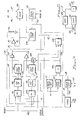
- focus acquire circuits 10 As best seen in Fig. 1, focus acquire circuits 10, detailed in Fig. 3, respond to an acquire focus command received over line 11 to establish an in-focus condition of lens 45 through fine actuator 46. Focus acquire circuits 10 supply a disable signal over line 12 to disable the focus maintenance loop 54F, which is a portion of the focus and tracking circuits 54 shown in Fig. 2. Focus acquire circuits 10 supply a focus acquiring actuator drive signal over line 13 through power amplifier 15 to the actuator 46.
- laser 67 supplies a constant intensity output beam of radiation to disk 30 (Fig. 2) to be reflected by disk 30 through later described optics to focus detector 62.
- Focus detector 62 supplies a focus error signal (FES) over line 63F to focus loop 54F and to focus acquire circuits 10, as detailed in Fig. 3.
- Focus acquire circuits 10 respond to FES on line 63F for controlling indication of a focus require for re-enabling focus loop 54F operation.
- the laser drive circuit 66 supplied laser drive signal over line 68 to laser 67 is measured by the laser drive drop detector 17; that is, when the detector lens 17 reaches an in-focus condition and detects a predetermined reduction in laser drive signal to laser 67. Such reduction in laser drive current is required at in-focus to enable the laser to maintain the constant power output radiation beam.
- Detector 17 then supplies an in-focus indicating signal over line 18 to focus acquire circuits 10.
- Circuits 10 combine the FES signal on line 63F with the laser drive in-focus signal to remove the lens drive signal from line 13 and enable focus loop 54F.
- FIG. 2 An optical recorder with which the present invention may be advantageously employed is shown in Fig. 2.
- a magnetooptic record disk 30 is mounted for rotation on spindle 31 by motor 32.
- Optical head carrying arm 33 on head arm carriage generally denoted by numeral 34 moves radially of disk 30.
- a frame 35 of recorder suitably mounts carriage 34 for reciprocating radial motions. The radial motions of carriage 34 enable access to anyone of a plurality of concentric tracks or circumvolutions of a spiral track for recording and recovering data on and from the disk.
- Linear actuator suitably mounted on frame 35, radially moves carriage 34 for enabling the track accessing.
- the recorder is suitably attached to one or more host processors 37, such host processors may be control units, personal computers, large system computers, communication systems, image process processors, and the like.
- Attaching circuits 38 provide the logical and electrical connections between the optical recorder and the attaching host processors 37.
- Microprocessor 40 controls the recorder including the attachment to the host processor 37. Control data, status data, commands and the like are exchanged between attaching circuits 38 and microprocessor 40 via bidirectional bus 43. Included in microprocessor 40 is a program or microcode storing read only memory (ROM) 41 and a data and control signal storing random access memory (RAM) 42.
- ROM read only memory
- RAM random access memory
- the optics of the recorder include an objective or focusing lens 45 mounted for focusing and tracking motions on head arm 33 by fine actuator 46.
- This actuator includes mechanisms for moving lens 45 toward and away from disk 30 for focusing and track following and seeking movements radially of disk 30; for example, for changing tracks within a range of 100 tracks so that carriage 34 need not be actuated each time a track adjacent to a track currently being accessed is to be accessed.
- Numeral 47 denotes the two-way light path between lens 45 and disk 30.
- magnet 48 provides a weak magnetic steering field for directing the remnant magnetization direction of a small spot on disk 30 illuminated by laser light from lens 45.
- the laser light spot heats the illuminate spot on the record disk to a temperature above the Curie point of the magnetooptic layer (not shown, but can be an alloy of rare earth and transitional metals as taught by Chaudhari et al., U. S. Patent 3,949,387). This heating enables magnet 48 to direct the remnant magnetization to a desired direction of magnetization as the spot cools below the Curie point temperature.
- Magnet 48 is shown as oriented in the "write” direction, i.e. binary ones are recorded on disk 30 normally are "north pole remnant magnetization".
- magnet 48 rotates so the south pole is adjacent disk 30.
- Magnet 48 control 49 which is mechanically coupled to rotatable magnet 48 as indicated by dashed line 50, controls the write and erase directions.
- Microprocessor 40 supplies control signals over line 51 to control 49 for effecting reversal of the recording direction.
- focus and tracking circuits 54 control both the coarse actuator 36 and fine actuator 46.
- the positioning of carriage 34 by actuator 36 is precisely controlled by control signals supplied by circuits 54 over line 55 to actuator 36. Additionally the actuator control by circuits 54 is exercised by control signals travelling over lines 57 and 58 respectively for focus and fine tracking and switching actions of fine actuator 46.
- the focus and tracking position sensing is achieved by analyzing laser light reflected from disk 30 over path 47, thence through lens 45, through one-half mirror 60 and to be reflected by half-mirror 61 to a so-called "quad detector" 62.
- Quad detector 62 has four photo elements which respectively supply signals on four lines collectively denominated by numeral 63 to focus and tracking circuits 54. Aligning one axis of the detector 62 with a track center line, track following operations are enabled. Focusing operations are achieved by comparing the light intensities detected by the four photo elements in the quad detector 62. Focus and tracking circuits 54 analyze the signals on lines 63 to control both focus and tracking.
- Microprocessor 40 supplies a control signal over line 65 to laser control 66 for indicating that a recording operation is to ensue.
- laser 67 is energized by control 66 to emit a high intensity laser light beam for recording; in contrast, for reading, the laser 67 emitted laser light beam is a reduced constant intensity for limiting heating the laser illuminated spot on disk 30 to below the Curie point.
- Control 66 supplies its control signal over line 68 to laser 67 and receives a feedback signal over line 69 indicating the laser 67 emitted light intensity.
- Control 68 adjusts the light intensity to the desired constant value.
- Laser 67 a semiconductor laser such as a Gallium arsenide diode laser, can be modulated by data signals so the emitted light beam represents the data to be recorded by such intensity modulation.
- data circuits 75 (later described) supply data indicating signals over line 78 to laser 67 for effecting such modulation.
- This modulated light beam passes through polarizer 70 (linearly polarizing the beam), thence through collimating lens 71 toward half mirror 60 for being reflected toward disk 30 through lens 45.
- Data circuits 75 are prepared for recording the microprocessor 40 supplied suitable control signals over line 76.
- Microprocessor 40 in preparing circuits 75 responds to commands for recording received from a host processor 37 via attaching circuits 38.
- Data circuits 75 are prepared, data is transferred directly between host processor 37 data circuits 75 through attaching circuits 38.
- Data circuits 75 also ancillary circuits (not shown) relating to disk 30 format signals, error detection and correction and the like. Circuits 75, during a read or recovery action strip the ancillary signals from the readback signals before supplying corrected data signals over bus 77 to host processor 37 via attachment circuits 38.
- Reading or recovering data from disk 30 for transmission to a host processor requires optical and electrical processing of the laser light beam from the disk 30. That portion of the reflected light (which has its linear polarization from polarizer 70 rotated by disk 30 recording using the Kerr effect) travels along the two-way light path 47, through lens 45 and half-mirrors 60 and 61 to the data detection portion 79 of the head arm 33 optics.
- Half-mirror or beam splitter 80 divides the reflected beam into two equal intensity beams both having the same reflected rotated linear polarization.
- the half-mirror 80 reflected light travels through a first polarizer 81 which is set to pass only that reflected light which was rotated when the remnant magnetization on disk 30 spot being accessed has a "north" or binary one indication. This passed light impinges on photo cell 82 for supplying a suit able indicating signal to differential amplifier 85.
- polarizer 81 passes no or very little light resulting in no active signal being supplied by photocell 82.
- polarizer 83 which passes only "south” rotated laser light beam to photo cell 84.
- Photocell 84 supplies its signal indicating its received laser light to the second input of differential amplifier 85.
- the amplifier 85 supplies the resulting difference signal (representing data) to data circuits 75 for detection.
- the detected signals include not only data that is recorded but also all of the so-called ancillary signals as well.
- data is intended to include any and all information-bearing signals, preferably of the digital or discrete value type.
- the rotational position and rotational speed of spindle 31 is sensed by a suitable tachometer or emitter sensor 90.
- Sensor 90 preferably of the optical sensing type that senses dark and light spots on a tachometer wheel (not shown) of spindle 31, supplies the "tach" signals (digital signals) to RPS circuit 91, which detects the rotational position of spindle 31 and supplies rotational information-bearing signals to microprocessor 40.
- Microprocessor 40 employs such rotational signals for controlling access to data storing segments on disk 30 as is widely practiced in the magnetic data storing disks. Additionally, the sensor 90 signals also travel to spindle speed control circuits 93 for controlling motor 32 to rotate spindle 31 at a constant rotational speed. Control 93 may include a crystal controlled oscillator for controlling motor 32 speed, as is well known.
- Microprocessor 40 supplies control signals over line 94 to control 93 in a usual manner.
- Figs. 3 and 4 illustrate the present invention in a preferred form.
- Fig. 3 shows circuits for implementing the invention
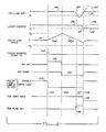
- Fig. 4 shows idealized signal waveforms which illustrate the operation of the Fig. 3-illustrated circuits.
- a reset pulse is supplied over line 102 for conditioning the focus acquire circuit 10 to a reference or initial state. This reference state opens both the tracking and focus servo loops and gives actuator 36 zero drive current.
- microprocessor 40 using its known disk recorder initializing algorithms, issues a focus acquire command signal over line 11 to focus acquire circuits 10 for conditioning those circuits to actuate actuator 46 to move lens 45 toward an in-focus condition.
- focus acquire signal 100 sets flip-flop (FF) 103 to the acquire state. This action causes FF 103 to supply a focus loop disable signal over line 12 to focus loop 54F to open or disable the focus loop 54F until focus has been acquired.
- reset signal 102 initially reset FF 103 to the focus loop 54F enabling state.
- the line 12 signal 104 goes to the open loop or disable loop 54F state.
- Signal 104 remains in the open loop state until an in-focus condition is detected, as represented by vertical dash line 108.
- Focus acquisition cycle has three phases, between vertical dashed lines 105 and 106 lens 45 is moved away from the optical disk 30 toward a most remote travel position represented by reference voltage V2. At dash line 106 the travel of lens 45 is reversed for moving it toward optical disk 30.
- the focus acquisition phase begins.
- Such focus acquisition phase involves the FES signal 129, the laser current signal 136 and the FES drive signal zero crossing 133 detecting peak detector 132, all as will become apparent.
- Focus acquire signal 100 also travels over line 11 to set FF 111 to a state for moving lens 45 away from disk 30. It should be noted that reset pulse on line 102, initially reset FF 111 to an inoperative state wherein no action or control is exercised by FF 111 over actuator 46.
- FF 112 set to the active condition actuates INT UP circuit 112 by signal 114 to generate a ramp signal 114A of the focus drive signal 14.
- Ramp signal 114A causes actuator 46 to move lens to the most remote position from disk 30, as represented by voltage V2.
- the ramp signal 114A travels from INT UP circuit 112 through isolating amplifier 113 to line 13.
- the second output signal from INT UP circuit 112 travels to voltage compare circuit 114, which receives V2 over line 116.
- FES on line 63F is a source for two of the in-focus indicating parameters.
- FES goes through a single sine wave cycle having an onset indicated by a predetermined point with respect to the zero crossing in-focus indicating of FES 129 varies with the design of a focus detector.
- threshold voltage V1 a near peak detector 131 indicates that the first peak of the single cycle sinusoid is being approached which indicates approachment of the in-focus condition.
- Near peak detector 131 is a voltage comparator which compares the voltage of FES 129 with the reference signal V1.
- the output signal 132 of FES near peak detector is signal 132 of Fig. 4.
- the second FES parameter is detected by zero crossing detector circuit 133, which responds to the FES 129 zero crossing to generate signal transition 134.
- the third parameter, in-focus input is the reduction of laser drive current drive signal received over line 142 from laser 67.
- the laser current drop detector 17 compares the laser drive signal amplitude on line 142 with the reference signal I2 on line 135. When equality between I2 and the line 142 signal is detected, as at point 137 of the laser current signal 136, detector 17 outputs a signal over line 18 corresponding to the horizontal dash line 108.
- AND circuit 145 receives the output signals from circuits 17, 131 and 133.
- AND circuit 145 When all three parameter signals are simultaneously present, AND circuit 145 outputs a signal substantially time coincident with vertical dash line 108 for resetting FF 103 to the focus loop 54F enabling state. Simultaneously, the line 146 signal also passes through OR circuit 124 for resetting FF 120 to terminate ramp signal 122A and turn off INT DOWN circuit 121 (terminates focus acquisition).
- the laser current remains at amplitude I2, as represented by numeral 138. In the rare event that focus is not actually acquired, then the laser current increases as represented by dash line 139, which is useful for indicating an out-of-focus state.
- Dash line 140 represents the shape of FES 129 for the event that focus is not acquired.
- Numeral 141 indicates FES 129 when focus is acquired.
- the line 16 drive signal is integrated within comparator 150 and compared with V2 and V3 signals respectively on lines 116 and 117. Comparator 150, upon detecting integrated values exceeding V2 or V3, sends a control signal to focus loop 54F for limiting its operation.
- Fig. 5 illustrates a modification of laser drive current loop detector 17.
- the laser drive signal received over line 142 goes to comparator 155 to be compared with the value I2 on line 135.
- the line 142 signal is also differentiated for detecting a peak of the laser drive current by differentiator 156.
- the output signals of circuits 155 and 156 are logically ANDed together in AND circuit 157 for supplying an in-focus parameter signal over line 18.
Landscapes
- Optical Recording Or Reproduction (AREA)
- Moving Of The Head For Recording And Reproducing By Optical Means (AREA)
Applications Claiming Priority (2)
| Application Number | Priority Date | Filing Date | Title |
|---|---|---|---|
| US155390 | 1988-02-12 | ||
| US07/155,390 US4998233A (en) | 1988-02-12 | 1988-02-12 | Acquiring focus in optical systems using a focus error signal and a laser drive signal |
Publications (2)
| Publication Number | Publication Date |
|---|---|
| EP0328501A1 true EP0328501A1 (de) | 1989-08-16 |
| EP0328501B1 EP0328501B1 (de) | 1993-04-21 |
Family
ID=22555235
Family Applications (1)
| Application Number | Title | Priority Date | Filing Date |
|---|---|---|---|
| EP89850037A Expired - Lifetime EP0328501B1 (de) | 1988-02-12 | 1989-02-07 | Gerät und Verfahren zum Erreichen einer Scharfeinstellung in einem optischen System |
Country Status (4)
| Country | Link |
|---|---|
| US (1) | US4998233A (de) |
| EP (1) | EP0328501B1 (de) |
| JP (1) | JPH0624069B2 (de) |
| DE (1) | DE68906047T2 (de) |
Families Citing this family (14)
| Publication number | Priority date | Publication date | Assignee | Title |
|---|---|---|---|---|
| US5101392A (en) * | 1988-11-21 | 1992-03-31 | Kabushiki Kaisha Toshiba | Information recording apparatus |
| JP2774609B2 (ja) * | 1989-09-18 | 1998-07-09 | 富士通株式会社 | ディスク装置及びディスク制御方法 |
| US5113384A (en) * | 1989-09-25 | 1992-05-12 | Hewlett-Packard Company | Focus capture method for magneto-optic disk drives |
| JPH0719381B2 (ja) * | 1989-10-04 | 1995-03-06 | 松下電器産業株式会社 | フォーカス引き込み方式 |
| JPH0485729A (ja) * | 1990-07-27 | 1992-03-18 | Nec Corp | 光学的再生装置 |
| US5233584A (en) * | 1990-09-04 | 1993-08-03 | International Business Machines Corporation | Optical disk device using high and low data-sensing criteria plus device recalibration for error control |
| JPH05159327A (ja) * | 1991-12-05 | 1993-06-25 | Hitachi Ltd | 光学式ディスクプレーヤにおけるフォーカスサーチ回路 |
| US5564013A (en) * | 1992-06-22 | 1996-10-08 | Matsushita Electric Industrial Co., Ltd. | Optical information recording and reproducing apparatus adapted to optically record and reproduce data in a sector, and method thereof |
| EP0840304B1 (de) * | 1993-04-02 | 2000-07-26 | Sony Corporation | Servosystem zum Fokussieren und Verfahren zum Ermöglichen der Erfassung eines Fokussierungsservosystems |
| US8496705B2 (en) | 1996-11-21 | 2013-07-30 | DePuy Mitek, LLCR | Method of anchoring autologous or artificial tendon grafts in bone |
| AU738044B2 (en) | 1996-11-21 | 2001-09-06 | Ethicon Inc. | Apparatus and methods for anchoring autologous or artificial tendon grafts in bone |
| KR100259972B1 (ko) * | 1997-01-21 | 2000-06-15 | 윤종용 | 메모리 셀당 2개 이상의 저장 상태들을 갖는 불휘발성 반도체 메모리 장치 |
| JP3563239B2 (ja) * | 1997-07-10 | 2004-09-08 | パイオニア株式会社 | フォーカス制御装置 |
| TW200509108A (en) * | 2003-08-06 | 2005-03-01 | Via Tech Inc | Method for obtaining the best focusing point of optical pickup and server system of its CD-ROM drive |
Citations (4)
| Publication number | Priority date | Publication date | Assignee | Title |
|---|---|---|---|---|
| US3949387A (en) * | 1972-08-29 | 1976-04-06 | International Business Machines Corporation | Beam addressable film using amorphous magnetic material |
| US4439848A (en) * | 1978-03-27 | 1984-03-27 | Discovision Associates | Focusing system for video disc player |
| EP0220039A2 (de) * | 1985-10-17 | 1987-04-29 | Optical Disc Corporation | Fokussteuerungsanlage für optischen Datenaufzeichner oder Leser |
| EP0234594A2 (de) * | 1986-02-28 | 1987-09-02 | Kabushiki Kaisha Toshiba | System zur Wiedergewinnung von Informationen aus einem optischen Speicher |
Family Cites Families (23)
| Publication number | Priority date | Publication date | Assignee | Title |
|---|---|---|---|---|
| FR2251876B1 (de) * | 1973-11-16 | 1977-09-23 | Thomson Brandt | |
| US4190775A (en) * | 1975-02-18 | 1980-02-26 | Agency Of Industrial Science & Technology | Optical memory playback apparatus |
| FR2304981A1 (fr) * | 1975-03-21 | 1976-10-15 | Thomson Brandt | Dispositif d'enregistrement optique d'informations |
| NL7904724A (nl) * | 1979-06-18 | 1980-12-22 | Philips Nv | Optische aftastinrichting met fokusseerstelsel. |
| JPS5694528A (en) * | 1979-12-28 | 1981-07-31 | Matsushita Electric Ind Co Ltd | Drawing-in method of focus servo |
| JPS5894143A (ja) * | 1981-12-01 | 1983-06-04 | Matsushita Electric Ind Co Ltd | 光学的記録再生装置 |
| JPS58101330U (ja) * | 1981-12-25 | 1983-07-09 | パイオニア株式会社 | 光学装置におけるフオ−カスサ−ボ引込装置 |
| US4446546A (en) * | 1981-12-31 | 1984-05-01 | Magnetic Peripherals Inc. | Focus initialization system for optical recording |
| JPS58121137A (ja) * | 1982-01-09 | 1983-07-19 | Sony Corp | 光学式デイスク再生装置のフオ−カス引込み回路 |
| JPS58155527A (ja) * | 1982-03-10 | 1983-09-16 | Hitachi Ltd | 光デイスクプレ−ヤのフオ−カス引き込み回路 |
| WO1983004329A1 (en) * | 1982-06-04 | 1983-12-08 | Sony Corporation | Optical disc reproducer |
| JPS6077023U (ja) * | 1983-11-01 | 1985-05-29 | パイオニア株式会社 | 記録情報読取装置のフオ−カスレンズ移動制御装置 |
| US4604739A (en) * | 1984-04-16 | 1986-08-05 | International Business Machines Corporation | Optical focus detection employing rotated interference patterns |
| US4636625A (en) * | 1984-09-06 | 1987-01-13 | Ricoh Company, Ltd. | Method and device for detecting focal point |
| DE3541002A1 (de) * | 1984-11-20 | 1986-05-28 | Olympus Optical Co., Ltd., Tokio/Tokyo | Optisches informationsaufnahme- und -wiedergabespeichersystem |
| US4740679A (en) * | 1985-02-27 | 1988-04-26 | Olympus Optical Co., Ltd. | Disc focus servo-circuit with ordered reference level setting means |
| US4700056A (en) * | 1985-11-13 | 1987-10-13 | Optotech, Inc. | Objective lens focus initialization system |
| US4762986A (en) * | 1986-03-10 | 1988-08-09 | Canon Kabushiki Kaisha | Automatic focussing system including in-focus position prediction means |
| JP2531942B2 (ja) * | 1986-04-14 | 1996-09-04 | ティアツク株式会社 | 光学式デイスク記録装置 |
| JPS6313261A (ja) * | 1986-07-02 | 1988-01-20 | Japan Storage Battery Co Ltd | 鉛電池の充電方法 |
| US4789974A (en) * | 1986-09-16 | 1988-12-06 | Matsushita Electric Industrial Co., Ltd. | Optical information recording/reproducing apparatus |
| US4841370A (en) * | 1986-11-17 | 1989-06-20 | Sanyo Electric Co., Ltd. | Automatic focusing circuit for automatically matching focus in response to video signal |
| US4794581A (en) * | 1987-06-25 | 1988-12-27 | International Business Machines Corporation | Lens support system enabling focussing and tracking motions employing a unitary lens holder |
-
1988
- 1988-02-12 US US07/155,390 patent/US4998233A/en not_active Expired - Fee Related
- 1988-12-20 JP JP63319702A patent/JPH0624069B2/ja not_active Expired - Lifetime
-
1989
- 1989-02-07 DE DE89850037T patent/DE68906047T2/de not_active Expired - Fee Related
- 1989-02-07 EP EP89850037A patent/EP0328501B1/de not_active Expired - Lifetime
Patent Citations (4)
| Publication number | Priority date | Publication date | Assignee | Title |
|---|---|---|---|---|
| US3949387A (en) * | 1972-08-29 | 1976-04-06 | International Business Machines Corporation | Beam addressable film using amorphous magnetic material |
| US4439848A (en) * | 1978-03-27 | 1984-03-27 | Discovision Associates | Focusing system for video disc player |
| EP0220039A2 (de) * | 1985-10-17 | 1987-04-29 | Optical Disc Corporation | Fokussteuerungsanlage für optischen Datenaufzeichner oder Leser |
| EP0234594A2 (de) * | 1986-02-28 | 1987-09-02 | Kabushiki Kaisha Toshiba | System zur Wiedergewinnung von Informationen aus einem optischen Speicher |
Also Published As
| Publication number | Publication date |
|---|---|
| US4998233A (en) | 1991-03-05 |
| DE68906047D1 (de) | 1993-05-27 |
| DE68906047T2 (de) | 1993-10-28 |
| EP0328501B1 (de) | 1993-04-21 |
| JPH01220129A (ja) | 1989-09-01 |
| JPH0624069B2 (ja) | 1994-03-30 |
Similar Documents
| Publication | Publication Date | Title |
|---|---|---|
| US5060210A (en) | Controlling head seeking speed in disk storage units by limiting displacement of head with respect to its supporting headarm | |
| US5138594A (en) | Reducing amplitude variations of optical disk readback signals and increasing reliability of track-crossing counts | |
| US5220546A (en) | Operating optical disk drives including calibrating a tracking error signal | |
| US4896311A (en) | Disk apparatus | |
| US5426625A (en) | Masking of tracking error signal abnormalities due to media defects | |
| EP0328501B1 (de) | Gerät und Verfahren zum Erreichen einer Scharfeinstellung in einem optischen System | |
| EP0189187B1 (de) | Magnetooptisches Plattenspeichersystem | |
| KR950013696B1 (ko) | 디스크 레코더 동작장치, 데이타 저장 장치, 디스크 드라이브 동작 방법 및 매체 라이브러리 동작 방법 | |
| EP0387224B1 (de) | Positionsservosystem und dessen Arbeitsweise | |
| US5396476A (en) | Sensing contamination level in an optical storage device | |
| US5912874A (en) | Calibrating an optical detector to minimize noise from undesired perturbations in disk surface | |
| US4789972A (en) | Selectively controlling the erasure in a magneto-optic recording medium | |
| US4989194A (en) | Optical information processing method of driving auto-focusing and/or auto-tracking means in accordance with a stored servo signal when irradiation of a record medium with light beam is stopped, and apparatus therefor | |
| EP0310250B1 (de) | Gerät für eine entfernbare Platte mit Regelung der Position der Rotation | |
| US6160774A (en) | Position sensor for tracking system for optical data storage | |
| US4916680A (en) | Magnetooptic recording member having selectively-reversed erasure directions in predetermined recording areas of the record member | |
| US5511228A (en) | Apparatus and method for employing a host mode setting command to turn-off or leave-on a laser in an optical disk drive | |
| US4937800A (en) | Method of recording using selective-erasure directions for magnetooptic record members | |
| JPS63138531A (ja) | 情報再生装置 | |
| JPH07147022A (ja) | 光ディスク装置 |
Legal Events
| Date | Code | Title | Description |
|---|---|---|---|
| PUAI | Public reference made under article 153(3) epc to a published international application that has entered the european phase |
Free format text: ORIGINAL CODE: 0009012 |
|
| AK | Designated contracting states |
Kind code of ref document: A1 Designated state(s): DE FR GB |
|
| 17P | Request for examination filed |
Effective date: 19891214 |
|
| 17Q | First examination report despatched |
Effective date: 19911001 |
|
| GRAA | (expected) grant |
Free format text: ORIGINAL CODE: 0009210 |
|
| AK | Designated contracting states |
Kind code of ref document: B1 Designated state(s): DE FR GB |
|
| REF | Corresponds to: |
Ref document number: 68906047 Country of ref document: DE Date of ref document: 19930527 |
|
| ET | Fr: translation filed | ||
| PLBE | No opposition filed within time limit |
Free format text: ORIGINAL CODE: 0009261 |
|
| STAA | Information on the status of an ep patent application or granted ep patent |
Free format text: STATUS: NO OPPOSITION FILED WITHIN TIME LIMIT |
|
| 26N | No opposition filed | ||
| PGFP | Annual fee paid to national office [announced via postgrant information from national office to epo] |
Ref country code: GB Payment date: 19950125 Year of fee payment: 7 |
|
| PGFP | Annual fee paid to national office [announced via postgrant information from national office to epo] |
Ref country code: FR Payment date: 19950128 Year of fee payment: 7 |
|
| PGFP | Annual fee paid to national office [announced via postgrant information from national office to epo] |
Ref country code: DE Payment date: 19950223 Year of fee payment: 7 |
|
| PG25 | Lapsed in a contracting state [announced via postgrant information from national office to epo] |
Ref country code: GB Effective date: 19960207 |
|
| GBPC | Gb: european patent ceased through non-payment of renewal fee |
Effective date: 19960207 |
|
| PG25 | Lapsed in a contracting state [announced via postgrant information from national office to epo] |
Ref country code: FR Effective date: 19961031 |
|
| PG25 | Lapsed in a contracting state [announced via postgrant information from national office to epo] |
Ref country code: DE Effective date: 19961101 |
|
| REG | Reference to a national code |
Ref country code: FR Ref legal event code: ST |