EP0328341B1 - Dispositif de verrouillage de ceintures d'un siège pour chargeurs - Google Patents
Dispositif de verrouillage de ceintures d'un siège pour chargeurs Download PDFInfo
- Publication number
- EP0328341B1 EP0328341B1 EP89301156A EP89301156A EP0328341B1 EP 0328341 B1 EP0328341 B1 EP 0328341B1 EP 89301156 A EP89301156 A EP 89301156A EP 89301156 A EP89301156 A EP 89301156A EP 0328341 B1 EP0328341 B1 EP 0328341B1
- Authority
- EP
- European Patent Office
- Prior art keywords
- seat
- operator
- controller
- switch
- implement according
- Prior art date
- Legal status (The legal status is an assumption and is not a legal conclusion. Google has not performed a legal analysis and makes no representation as to the accuracy of the status listed.)
- Expired
Links
Images


Classifications
-
- B—PERFORMING OPERATIONS; TRANSPORTING
- B60—VEHICLES IN GENERAL
- B60R—VEHICLES, VEHICLE FITTINGS, OR VEHICLE PARTS, NOT OTHERWISE PROVIDED FOR
- B60R22/00—Safety belts or body harnesses in vehicles
- B60R22/48—Control systems, alarms, or interlock systems, for the correct application of the belt or harness
-
- E—FIXED CONSTRUCTIONS
- E02—HYDRAULIC ENGINEERING; FOUNDATIONS; SOIL SHIFTING
- E02F—DREDGING; SOIL-SHIFTING
- E02F9/00—Component parts of dredgers or soil-shifting machines, not restricted to one of the kinds covered by groups E02F3/00 - E02F7/00
- E02F9/24—Safety devices, e.g. for preventing overload
-
- B—PERFORMING OPERATIONS; TRANSPORTING
- B60—VEHICLES IN GENERAL
- B60R—VEHICLES, VEHICLE FITTINGS, OR VEHICLE PARTS, NOT OTHERWISE PROVIDED FOR
- B60R22/00—Safety belts or body harnesses in vehicles
- B60R22/48—Control systems, alarms, or interlock systems, for the correct application of the belt or harness
- B60R2022/4808—Sensing means arrangements therefor
- B60R2022/4816—Sensing means arrangements therefor for sensing locking of buckle
-
- B—PERFORMING OPERATIONS; TRANSPORTING
- B60—VEHICLES IN GENERAL
- B60R—VEHICLES, VEHICLE FITTINGS, OR VEHICLE PARTS, NOT OTHERWISE PROVIDED FOR
- B60R22/00—Safety belts or body harnesses in vehicles
- B60R22/48—Control systems, alarms, or interlock systems, for the correct application of the belt or harness
- B60R2022/4808—Sensing means arrangements therefor
- B60R2022/4858—Sensing means arrangements therefor for sensing pressure on seat
-
- B—PERFORMING OPERATIONS; TRANSPORTING
- B60—VEHICLES IN GENERAL
- B60R—VEHICLES, VEHICLE FITTINGS, OR VEHICLE PARTS, NOT OTHERWISE PROVIDED FOR
- B60R22/00—Safety belts or body harnesses in vehicles
- B60R22/48—Control systems, alarms, or interlock systems, for the correct application of the belt or harness
- B60R2022/4883—Interlock systems
- B60R2022/4891—Interlock systems preventing use of the vehicle when the seatbelt is not fastened
Definitions
- the present invention relates generally to industrial implements having hydraulically operated working tools and more particularly, although not exclusively, to an operator restraint interlock for skid steer loaders.
- a controller can determine when the operator restraint mechanism is not being utilised in conjunction with the operator coming and going from his seat.
- US-A-4,389,154 discloses a loader boom controller and addresses the problem of how to avoid falsely deactivating the loader boom when the operator transiently leaves his seat due to operating on rough terrain.
- the present invention is defined in the appended claims and provides a loader having hydraulically operated boom and bucket mechanisms controllable from the operator seat wherein switches sense the presence of the operator in the seat and the buckling of the seat belt.
- An electronic controller is operably associated with the seat and belt switches and solenoid valves in the hydraulic system and the starter relay. The controller requires proper sequencing of the activation of the seat and belt switches before permitting the starter to be energised, thereby controlling the starting of the loader engine, or permitting the energising of the hydraulic solenoid valves to control the flow of hydraulic fluid to the hydraulic cylinders for the boom and bucket.
- the controller also includes a delay associated with the seat switch so that a reactivation of the seat switch within the delayed period of time would allow the hydraulic system to operate without requiring a resequencing of the activation of the seat and belt switches.
- the invention overcomes the aforementioned disadvantages of the prior art by providing an interlock to be used in conjunction with both the seat and operator restraint apparatus sensors to control the operation of the working tool apparatus on a skid steer loader, for example, so as to encourage the use of the operator restraint mechanism during operation of the implement.
- a predetermined sequence of actuation of the seat and seat belt sensors may be required before the operation of the hydraulic system and/or engine of the implement is/are enabled.
- the engine is permitted to continue operation, once it has been started, without requiring any resequencing of the activation of the seat and seat belt sensors.
- a delay mechanism may be incorporated into the controller so that the opening of the seat switch for a short period of time would not require a resequencing of the actuation of the seat belt switches before enabling the hydraulic system of the loader.
- Engagement of the operator restraint mechanism after the operator sits in the operator seat may be required to enable the operation of the hydraulic system of the implement.
- An advantage of the present invention is that the use of the operator restraint mechanism is more convenient than bypassing the operation of the controller.
- the operator restraint apparatus may utilise a sealed switch having a cammed contact lever engageable with a male buckle portion of the apparatus for actuation thereof.
- the invention to provide an interlock associated with both a seat sensor and an operator restraint apparatus sensor for enabling the operation of an implement, which is durable in construction, inexpensive of manufacture, carefree of maintenance, facile in assemblege and simple and effective in use.
- the loader 10 is provided with a frame 12 having wheels 13 mounted thereon mobilely to support the loader 10 over the ground G.
- An engine 14 is mounted on the frame 12 and serves as the power plant for driving the loader 10 and the working tool assembly 15.
- the means of propulsion is of conventional nature such as described in US-A-3,810,517.
- the engine 14 is also of a conventional nature and includes a conventional starter mechanism (not shown) connected to the electrical system of the loader 10, as will be described in greater detail below, to effect a starting of the engine 14.
- the working tool assembly 15 is movably mounted on the frame 12 to perform a variety of working tasks typically associated with such implements.
- the working tool assembly 15 depicted in Figures 1 and 3 includes a bucket 16 pivotally mounted on a pair of transversely-spaced boom arms 17 which are in turn pivotally connected to the frame 12.
- a pair of bucket hydraulic cylinders 18 interconnect the bucket 16 and respective boom arms 17 to provide a means for pivotally moving the bucket 16 relative to the boom arms 17.
- a pair of boom hydraulic cylinders 19 interconnect the respective boom arms 17 and the frame 12 to provide pivotal movement of the boom arms 17 relative to the frame 12.
- the frame 12 supports an operator compartment 20 forwardly of the engine 14 and immediately rearwardly of the bucket 16 to permit a view of the operation thereof.
- the operator compartment 20 is provided with an operator seat 22 from which the operator can control the movements of the loader 10 and the working tool assembly 15 by means of control levers 21 and/or pedal controls (not shown) in a conventional manner.
- the seat 22 is equipped with a seat switch 23 operable to sense the presence of the operator in the seat 22 in a manner described in detail in US-A-4,385,863, the descriptive portions thereof being incorporated herein by reference.
- the operator compartment 20 is also provided with an operator restraint mechanism 25 in the form of a seat belt as can be seen in greater detail in Figure 4a.
- a female receptor portion 27 of the seat belt 25 is provided with a belt switch 28 having a contact lever 29 positioned for engagement with a male buckle portion 26 of the seat belt 25 such that connection of the male buckle portion 26 with the female receptor portion 27 actuates the belt switch 28 to sense the engagement of the operator restraint mechanism 25 in an operative position in which the seat belt 25 may be wrapped around the operator to restrain him in the seat 22.
- the belt switch 28 will be open to prevent the passage of current therethrough, which will be described in greater detail below.
- the lower part 27a of the female receptor portion 27 is deepened over that previously known in the art to accommodate the depth of a sealed seat switch 28, such as the Cherry Waterproof Subminiature Snap Action Switch, Model DC.
- the sealed switch 28 is fastened into place in the interior of the female receptor portion 27 by a pair of pins 28a extending through the sealed switch 28 and then secured, such as by gluing, to the outside wall 27b of the female receptor portion 27 and to an internal reinforcing web flange 27c, fixing the sealed switch 28 therebetween.
- the contact lever 29 has a curved camming portion 29a to facilitate actuation thereof by the insertion of the male buckle portion 26 into engagement with the female receptor portion 27.
- the use of a sealed switch 28 eliminates the problems of dirt fouling the contacts of standard microswitches to increase the performance and reliability characteristics of the operator restraint mechanism 25.
- the hydraulic system 30 includes a pump 32 operably driven from the engine 14 to provide fluid under pressure from the reservoir 33 throughout the conduits 36, 38 interconnecting the pump 32 and the hydraulic actuators 18, 19, respectively.
- a conventional control valve 34 controls the direction of fluid from the pump 32 throughout the conduits 36, 38, thereby operably controlling the movement of the hydraulic cylinders 18, 19 and the operation of the working tool assembly 15.
- the conduit 36 interconnecting the control valve 34 and the boom hydraulic cylinders 19 is provided with a hydraulic solenoid valve 37 which is operable to block the flow of fluid through the conduit 36 and thereby disable the operation of the boom hydraulic cylinders 19.
- the conduit 38 interconnecting the bucket hydraulic cylinders 18 and the control valve 34 is also provided with a hydraulic solenoid valve 39 operable to block the flow of fluid through the conduit 38 and disable the operation of the bucket hydraulic cylinders 18.
- the solenoid valves 37, 39 are positioned so that on energisation thereof by the electrical system to which the solenoid valves 37, 39 are connected, the hydraulic system 30 will be enabled which will permit the working tool assembly 15 to be operated. Without being energised, the solenoid valves 37, 39 retain the hydraulic system 30 in a disabled condition, locking up the operation of the working tool assembly 15.
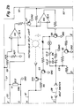
- Figure 5 includes a schematic representation of the electrical system with current coming from the battery B and the energising control coming from the electrical system 40 forming the controller described in greater detail with respect to Figure 2a below.
- the electrical circuit 40 forming the controller of the boom solenoid valve 37, the bucket solenoid valve 39 and the starter relay for the engine 14 can best be seen.
- the voltage from the battery V BAT is supplied through terminal connection 42 and through line 43 to relay contacts K2-1, K1-1, K4-1, K3-1 and to the open seat switch 23. Since neither the open seat switch nor the relay contacts draw any load from the battery B, the controller 40 will stay in this inactive state without weakening the battery B.
- the service override switch 45 is open drawing the interconnected normal operation switch 46 into its closed position, all the relay coils, K1, K2, K3, K4 and K5 are off and relay contacts K1-1, K2-1, K3-1, K4-1, K5-1, K2-2, and K5-2 are open, while relay contacts K1-2 and K2-3 are normally closed.
- Energising the relay coil K1 closes relay contact K1-1 and opens contact K1-2.
- the opening of contact K1-2 prevents voltage from reaching relay coil K5 and thereby prevents relay coils K3 and K4 from being energised.
- the closing of relay contact K1-1 supplies voltage to the power terminal of IC4 enabling comparators AA, BB, and CC and enabling oscillator amplifier DD.
- the closing of contact K1-1 supplies voltage to the input of the voltage regulator IC1 which provides five volts to the power terminal of IC2 enabling comparators A and B.
- the five volts from the voltage regulator IC1 is also applied to a divider formed by resistors R18 and R19 via line 53 to make a 2.5 volt reference.
- the closing of relay contact K1-1 also supplies voltage via line 55 to relay coil K2 and via lines 57, 59 to a divider formed by resistors R25 and R27.
- the divider formed by resistors R25 and R27, and comparators AA and BB provide the function of a voltage monitor.
- Resistors R25 and R27 are sized to provide greater than five volts to the positive terminal of comparator AA whenever the voltage in line 57 is greater than 17 volts.
- the comparator AA outputs source current into the base of transistor Q7 which turns on, pulling the positive input terminal of comparator BB to ground, which in effect turns comparator BB off and pulls the base of transistor Q6 to ground, preventing transistor Q6 from being turned on.
- relay coil K5 is prevented from being energising which in turn prevents relay coils K3 and K4 from being energised.
- the voltage from the divider formed by resistors R25 and R27 is less than five volts.
- the comparator AA output then pulls the base of transistor Q7 to ground, preventing transistor Q7 from turning on. This allows the five volts on line 53 to be applied to the positive terminal of comparator BB which in turn outputs source current to the base of transistor Q6 to permit relay coil K5 to energise by the current applied thereto.
- Closing relay contact K1-1 also supplies voltage via a line 57 to the divider formed by resistors R22 and R24.
- the voltage from this divider and the voltage fed back by resistor R23 determines the trip threshold of an oscillator amplifier DD.
- the amplitude of the signal at capacitor C6 also increases.
- the output of the amplifier DD is high when the charge on the capacitor C6 is lower than the voltage on the positive input of the amplifier DD.
- the capacitor C6 is then charged through resistor R21 until the voltage on it exceeds the voltage on the positive input of amplifier DD.
- the output of amplifier DD then goes low and discharges capacitor C6 until the voltage on it goes below the positive input on the amplifier DD.
- the resistor R23 causes voltage on the positive input of amplifier DD to be higher when the output of amplifier is high and lower when the output of amplifier DD is low. This feature provides the changes to the positive input of amplifier DD required for the oscillator to oscillate and also determines the magnitude of the charge on the capacitor C6.
- Comparator CC performs the same function for transistor Q4 and relay coil K2 and for transistors Q2, Q3 and Q1 and relay coil K1.
- the 2.5 volt reference is compared to the voltage at the negative input of comparator A. If the voltage on the negative input is greater than 2.5 volts, the output of comparator A turns on, shunting compacitor C3 and pulling the negative input of comparator B to ground. If the negative input of comparator B is lower than 2.5 volts, then the output of comparator B turns off allowing five volts to be applied to the positive input of comparator CC.
- relay coil K2 With five volts supplied to the positive input of comparator CC, relay coil K2 is energised, closing relay contacts K2-1, K2-2 and opening relay contact K2-3. The opening of relay contact K2-3 removes resistor R9 from the base of transistor Q3, which turns control of the current through relay coil K1 over to transistors Q1, Q3 and Q2 and to comparator CC as explained above.
- the closing of the seat switch 23 provides current to the belt switch 28 via line 61.
- the closing of the seat belt switch 28 supplies voltage to the base of transistor Q3, which overrides the control from transistor Q2 and forces transistor Q3 to turn off, preventing current from reaching the base of transistor Q1.
- relay coil K1 With transistor Q1 turned off, relay coil K1 is deenergised, causing relay contacts K1-1 to open, but since relay coil K2 is energised, relay contact K2-1 provides voltage in the same manner as described above for relay contact K1-1.
- the energising relay coil K1 also causes contact K1-2 to close. Current is then supplied through the closed contacts K2-2 and K1-2 to the base of transistor Q5, turning transistor Q5 on and pulling the base of transistor IC3 to ground, which turns off the transistor IC3 and the fasten seat belt light.
- Closed relay contact K5-1 allows the voltage from the ignition switch V IGN to energise relay coil K4, closing relay contact K4-1 which in turn allows the battery voltage V BAT to be applied to the boom solenoid valve 37 and the bucket solenoid valve 39, enabling their operation.
- relay coil K5 will be deenergised, opening relay contacts K5-1 and K5-2.
- the opening of relay contact K5-1 will deenergise the relay coil K4, causing relay contact K4-1 to open and interrupt voltage to the hydraulic solenoid valves 37, 39 to disable their operation.
- Opening relay contact K5-2 will deenergise the relay coil K3, causing relay contact K3-1 to open; however, while this will prevent a restarting of engine 14, the closing of contact K3-1 will not turn off the engine 14 if it is already running.
- the opening of the seat switch 23 removes voltage from the negative input of comparator A, allowing resistor R15 to pull the negative input of comparator A low, turning off the output of comparator A. With the output of comparator A off, the capacitor C3 is permitted to charge through resistor R17 toward the five volts carried by line 53. When the voltage on capacitor C3 reaches 2.5 volts, the output of comparator B will turn on, pulling the positive input of comparator CC to ground, which turns the output of comparator CC on to pull the bases of transistors Q4 and Q2 to ground, and turns transistors Q4 and Q2 off to deenergise relay coil K1 and K2. This situation will return the circuit to the initial conditions of power off described above.
- the output comparator A will be turned on removing the charge from C3 and permitting resumption of the normal operation as described above.
- the charging of capacitor C3 upon the opening of the seat switch 23 provides a delay for a period of time equal to approximately three seconds for the seat switch 23 to be reclosed without requiring a resequencing of the closing of the seat switch 23 and the seat belt switch 28.
- the controller 40 can be placed into a service mode by moving a service switch 45 into a closed position which, because of the interconnection between the service switch 45 and a normal operation switch 46, moves the normal operation switch 46 into an open position.
- the service switch 45 With the service switch 45 closed, the voltage from the start V START will bypass the relay contact K5-2 and energise the relay coil K3 allowing the voltage from the battery V BAT to be supplied to the starter relay over the closed relay contact K3-1 and permit the engine 14 to be started.
- the open normal operation switch 46 will prevent the relay coil K4 from being energised, keeping relay contact K4 open and preventing the voltage from the battery V BAT from being supplied to the hydraulic solenoids 37, 39 through the relay contact K4-1.
- FIG. 2e and 2f an alternative configuration of the electrical circuit can be seen.
- One way to bypass the operation of the seat switch 23 is to hard wire a jumper line across the switch 23 so that the circuit never sees the seat switch 23 open when the operator leaves the seat.
- a voltage drop of approximately 1.2 volts can be realised across the switch 23. Any attempt to hard wire a jumper line across the switch 23 would take the diodes D2 and D3 out of the circuit and, therefore, prevent the voltage drop from being realised.
- the resultant operation of the comparator AA is similar to that noted above. If the voltage at the positive terminal is greater than the voltage at the negative terminal, the comparator AA will output source current to the base of transistor Q7, turning transistor Q7 on, which as noted above with respect to Figures 2a and 2b, turns the entire system off. Under normal circumstances, the divider formed by resistors R25 and R27 is sized such that the voltage through line 47 to the positive terminal of comparator AA is always less than the voltage through line 48 to the negative terminal because of the voltage drop caused by the diodes D2 and D3. If the seat switch 23 is bypassed, taking the diodes D2 and D3 out of the circuit, the voltage at the positive terminal of comparator AA will be greater than the reference voltage at the negative terminal, causing the system to turn off.
- Figures 2e and 2f provides both a voltage protection feature for the entire circuit and an anti-bypass feature for the seat switch 23.
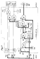
- FIG. 6 depicts the initial state of the controller 40 with current from the battery being supplied to the seat switch 23, an ignition switch 70, and a starter switch 72.
- the normal operation switch 46 is in a closed position forcing the interconnected service override switch 45 into an open position.
- the seat belt switch 28 is also open.
- the logic diagram includes six AND gates 80, 82, 84, 85, 86 and 88, and one OR gate 90, and a Set/Reset Latch 95, the operation which will be described in greater detail below.
- the controller 40 is also provided with diagnostic lights indicating the operation of the seat switch, belt switch and timer, as well as diagnostic lights indicating operation of the hydraulic solenoid interlocks and the start relay interlock.
- a signal inverter 89 is provided on three of the terminals and AND gates 82, 84 and 85.
- the external output to be affected by the controller includes the starter relay interlock, the hydraulic interlocks in the form of the solenoid valves 37, 39 and a fasten seat belt light which tells the operator that he must fasten or refasten the seat belt to enable the operation of the loader 10.
- Figure 7 depicts the manner in which the controller 40 is awakened.
- the operator sits in the seat, closing the seat switch 23, to provide a signal along lead 101 to the open belt switch 28 and along lead 103 to provide a signal to the b terminal of AND gate 80, a signal to the b terminal of AND gate 82, and a signal to the b terminal of AND gate 85.
- the closing of the seat switch 23 also illuminates the diagnostic seat light and sets the time delay. Since AND gate 80 reads only one signal at its two terminals, the belt diagnostic light remains unlit. Because of the signal inverter 89, the AND gate 82 reads a signal at both the a and b terminals and outputs a signal to the b terminal of AND gate 84 and to the set terminal S of the Set/Reset Latch 95.
- the activation of the Set/Reset Latch 95 provides on the output of a signal from the Q terminal to illuminate the timer light, provide a signal to the c terminal of AND gate 84, provide a signal through the voltage monitor to the b terminal of AND gate 88 and the b terminal of AND gate 86. Since the AND gate 84 is reading no signal at its a and b terminals (due to the signal inverter 89), AND gate 84 has no output. Likewise, the lack of signal at the a and c terminals at AND gate 86 and 88 prevents any output therefrom.
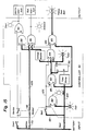
- the operator can enable operation of the loader 10 by closing the ignition and starter switches 70, 72 as reflected in Figure 9.
- the signal from the closed ignition switch 70 passes through the closed normal operation switch 46 and enters the a terminal of AND gate 86. Since AND gate 86 now reads a signal at all three of its input terminals, the output signal illuminates the solenoid diagnostic light and activates the hydraulic interlock in the form of energising the solenoid valves 37, 39 to enable operation of the loader hydraulic system 30 as described above.
- the signal from the closed starter switch 72 bypasses the open service override switch via lead 107 to provide a signal at the a terminal of AND gate 88.
- Figure 11 depicts the logic operation when the operator is bounced up in the seat, opening the seat switch 23.
- the opening of seat switch 23 terminates the signal along leads 101, 103 and 105, directly shutting off AND gates 80, 82, 84 and 85. So long as the seat switch 23 has remained open for less than 3 seconds, the time delay will not have actuated, leaving the Set/Reset Latch outputting a signal from its Q terminal to illuminate the time diagnostic light and provide a signal from a voltage monitor to the b terminals of AND gates 86 and 88.
- Figure 12 depicts the operator reexerting his weight upon the seat, closing the seat switch 23, the signal is reinstated along leads 101, 103 and 105 in the same manner as reflected in Figure 10 to reenergise the hydraulic interlock and enable the operation of the boom and bucket controls.
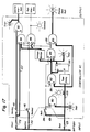
- Figure 13 reflects the logic operation for the alternative condition, the lack of presence of the operator in the seat, i.e. leaving the seat switch 23 open, for a period of time greater than three seconds.
- the time delay is activated sending a signal to the reset terminal R of the Set/Reset Latch 95 turning off the Set/Reset Latch 95 and eliminating the signal from the Q terminal, which in turn eliminates a signal through the voltage monitor to the b terminals of AND gates 86 and 88.
- Figures 13 and 14 can be referred to as the anti-tie-down feature. It is possible for the operator to bypass the logics of the controller as reflected in Figures 7 and 8 by sitting in the seat and fastening the seat belt behind the operator. As soon as the operator leaves his seat, as reflected in Figure 11, the hydraulic interlock is deenergised preventing operation of the boom and bucket controls. Irrespective of the condition of the belt switch 28. If the operator has exited the loader 10 leaving the engine running and the seat belt fastened for a period of time greater than three seconds, the operator will find that he must resequence the closing of the seat switch 23 and the belt switch 28 to enable operation of the hydraulically actuated boom and bucket.
- Figure 14 reflects the logic operation following the scenario set forth in the preceding paragraph.
- the operator who has been absent from his seat for a period of time greater than three seconds returns to the seat closing the seat switch 23.
- the resulting signal along leads 101, 103 and 105 and the already closed belt switch 28 illuminates the seat diagnostic light, activates AND gate 80 to illuminate the belt diagnostic light, recharges the time delay and provides a signal to the b terminal of AND gate 85, the a and b terminal of AND gate 82 and the a terminal of AND gate 84.
- the AND gate 82 reads only a signal at the b terminal and does not output a signal to the set terminal S of the Set/Reset Latch 95 or to the b terminal of AND gate 84.
- the signal inverter 89 at the a terminal of AND gate 85 causes AND gate 85 to read a signal at both the a and b terminals and, therefor, output a signal to illuminate the fasten seat belt light externally of the controller. Since AND gate 86 is not receiving a signal at either the b or c terminals, the hydraulic interlock is not energised and the boom and bucket controls remain inoperative.
- Figure 15 depicts the subsequent operation to that described above with respect to Figure 14, an unfastening of the seat belt and an opening of the seat belt switch 28. Removing the signal from lead 105 by the opening of the belt switch 28 removes the inverted signal from the a terminal of AND gate 82. The resultant output of AND gate 82 provides a signal to the inverted b terminal of AND gate 84 and to the set terminal S of the Set/Reset Latch 95. As described above with respect to Figure 7, the output signal from terminal Q of the Set/Reset Latch 95 turns on the timer diagnostic light and provides a signal to the b terminals of AND gates 86 and 88.
- a subsequent reclosing of the belt switch 28 provides a signal identical to that described above with respect to Figure 8, turning off the fasten seat belt light and, since the ignition switch 70 and the normal operation switch 46 has already been closed, providing a signal to the a terminal of AND gate 86, the logic operation will be identical to that described above with respect to Figure 10, energising the hydraulic interlock and enabling the operation of the boom and bucket controls.
- the controller also provides a service override feature depicted in Figure 16.
- the service override feature permits the starting and running of the engine 14; however, the hydraulic interlock cannot be energised to enable operation of the working tool assembly 15.
- the closing of the seat switch 23 while the service override switch is closed, as reflected in Figure 17, provides a signal along leads 101 and 103 in a manner similar to that described above with respect to Figure 7.
- controller logic cannot be bypassed merely by starting the engine 14 using the service override switch 45, sitting in the seat 22 without buckling the seat belt 25, and then flipping the normal operation switch 46, because no signal is received at the c terminal of AND gate 86 to permit an enabling of the hydraulic interlock.
- the controller logic shown in Figure 14 if the operator first buckles the seat belt 25 and then sits in the seat 22, no signal would be sent to the b terminal of AND gate 86, thereby disabling the hydraulic system 30.
Landscapes
- Engineering & Computer Science (AREA)
- Mining & Mineral Resources (AREA)
- Civil Engineering (AREA)
- General Engineering & Computer Science (AREA)
- Structural Engineering (AREA)
- Automation & Control Theory (AREA)
- Mechanical Engineering (AREA)
- Component Parts Of Construction Machinery (AREA)
- Forklifts And Lifting Vehicles (AREA)
Claims (18)
- Engin comportant un châssis mobile (12); un poste d'opérateur (20) monté sur le châssis et comprenant un siège (22) sur lequel l'opérateur est assis pendant le fonctionnement de l'engin; des moyens de travail (15) montés mobiles sur le châssis en vue d'exécuter des tâches commandées par l'opérateur depuis le siège; des moyens d'actionnement (18, 19) associés d'une manière fonctionnelle aux moyens de travail pour effectuer sélectivement un déplacement des moyens de travail par rapport au châssis; des moyens moteurs (14) montés sur le châssis et aptes à opérer pour commander les moyens d'actionnement et pour effectuer un déplacement de l'engin, des premiers moyens détecteurs (23) reliés d'une manière fonctionnelle au siège (22) pour détecter la présence de l'opérateur sur le siège; et des moyens de commande (40) associés d'une manière fonctionnelle aux premiers moyens détecteurs (23) et aux moyens moteurs (14) pour rendre les moyens d'actionnement inopérants si l'opérateur quitte son siège pendant une période supérieure à une période de temps prédéterminée, caractérisé en ce que l'engin comporte également un mécanisme de retenue d'opérateur (25) comportant une position active dans laquelle le mécanisme de retenue d'opérateur est apte à opérer pour maintenir l'opérateur sur le siège, et une position inactive dans laquelle l'opérateur n'est pas retenu sur le siège; des seconds moyens détecteurs (28) reliés d'une manière fonctionnelle au mécanisme de retenue d'opérateur (25) pour détecter le placement du mécanisme de retenue d'opérateur dans la position active, l'organe de commande (40) étant associé d'une manière fonctionnelle aux seconds moyens détecteurs (28) et apte à opérer pour empêcher le démarrage des moyens moteurs (14), à moins que les premier et second détecteurs ne soient activés selon une séquence prédéterminée, les moyens de commande étant également associés d'une manière fonctionnelle aux organes d'actionnement (18, 19) pour empêcher le fonctionnement de ceux-ci, lorsque le mécanisme de retenue d'opérateur est déplacé de la position active dans la position inactive pendant que les moyens moteurs sont rendus opérants, l'organe de commande empêchant la remise en action des moyens d'actionnement, à moins que les premiers et seconds moyens détecteurs ne soient activés au cours de ladite séquence prédéterminée.
- Engin selon la revendication 1, dans lequel les moyens moteurs comportent un moteur (14) mis en marche d'une manière fonctionnelle en conjonction avec la fermeture d'un circuit électrique, les moyens de commande (40) étant reliés d'une manière fonctionnelle au circuit électrique afin de maintenir celui-ci ouvert, pour ainsi empêcher le démarrage du moteur, à moins que les premiers et seconds moyens détecteurs (23, 28) ne soient activés selon ladite séquence prédéterminée.
- Engin selon la revendication 1 ou 2, dans lequel la séquence d'activation prédéterminée des premiers et seconds moyens détecteurs (23, 28) consiste d'abord à détecter la présence de l'opérateur sur le siège (22) et puis à détecter le déplacement du mécanisme de retenue d'opérateur (25) de la position inactive dans la position active.
- Engin selon l'une quelconque des revendications précédentes et comportant en outre' des moyens de temporisation associés d'une manière fonctionnelle aux premiers moyens détecteurs (23) pour temporiser pendant une période de temps prédéterminée la réception active par les moyens de commande (40) d'un signal représentatif d'une désactivation des premiers moyens détecteurs, afin d'indiquer que l'opérateur a quitté le siège (22).
- Engin selon la revendication 4, dans lequel les moyens de commande (40) exigent ladite séquence d'activation prédéterminée des premiers et seconds moyens détecteurs (23, 28) après la réception active de la désactivation des premiers moyens détecteurs (23) indiquant que l'opérateur a quitté le siège (22), avant que les moyens de commande ne rendent les moyens d'actionnement (45, 46, 70, 72) opérants, à moins que les premiers moyens détecteurs (23) ne soient réactivés pour indiquer la présence de l'opérateur sur le siège (22).
- Engin selon la revendication 5, dans lequel les moyens d'actionnement comportent des vérins hydrauliques (18, 19) reliés à un circuit hydraulique sous pression commandé d'une manière fonctionnelle par les moyens moteurs (14), le circuit hydraulique comportant une soupape à solénoïde hydraulique (37, 39) apte à opérer pour bloquer sélectivement l'écoulement d'un fluide hydraulique à travers le circuit hydraulique en direction des vérins hydrauliques et pour ainsi rendre les vérins hydrauliques inopérants.
- Engin selon la revendication 6, dans lequel les moyens de commande (40) sont reliés d'une manière fonctionnelle à la soupape à solénoïde hydraulique (37, 39) pour activer celle-ci sélectivement en vue de rendre les moyens d'actionnement inopérants (18, 19).
- Engin selon l'une quelconque des revendications 5 à 7, lorsqu'elles sont dépendantes de la revendication 2, dans lequel les moyens de commande (40) sont reliés d'une manière fonctionnelle audit circuit électrique pour fermer celui-ci uniquement lors de la réception de l'activation des seconds moyens détecteurs (28) indiquant que le mécanisme de retenue d'opérateur a été déplacé dans la position active après réception de l'activation des premiers moyens détecteurs (23) indiquant la présence de l'opérateur sur le siège (22), mais avant réception d'une quelconque réactivation des premiers moyens détecteurs indiquant que l'opérateur a quitté le siège.
- Engin selon l'une quelconque des revendications précédentes, dans lequel les premiers moyens détecteurs (23) comportent des moyens anti-court-circuit (80, 82, 84, 85, 89) associés aux moyens de commande (40) pour détecter si les premiers moyens détecteurs (23) ont été court-circuités et pour ensuite empêcher le fonctionnement de l'engin.
- Engin selon la revendication 9, dans lequel les moyens de commande (40) comportent un circuit électrique relié aux premiers et seconds moyens détecteurs (23, 28), les moyens anti-court-circuit opérant une chute de tension au niveau des premiers moyens détecteurs (23), et le circuit électrique comportant un comparateur (84) apte à opérer pour rendre l'engin inopérant, lorsque la chute de tension n'a pas lieu.
- Engin selon la revendication 6, dans lequel les premiers moyens détecteurs (23) sont reliés d'une manière fonctionnelle à la soupape à solénoïde hydraulique de façon qu'une désactivation des premiers moyens de détection active la soupape à solénoïde hydraulique pour rendre les moyens de travail (15) inopérants.
- Engin selon la revendication 2, ou l'une quelconque des revendications 3 à 11, lorsqu'elles sont dépendantes de celle-ci, dans lequel le commutateur de siège (23) comporte un moyen pour opérer une chute de tension pour un courant passant à travers lui à partir du circuit électrique, les moyens de commande (40) étant aptes à opérer pour empêcher le démarrage du moteur (14) en maintenant le circuit électrique ouvert, à moins que la chute de tension n'ait lieu.
- Engin selon l'une quelconque des revendications précédentes, dans lequel les moyens de commande (40) sont aptes à opérer pour empêcher le démarrage des moyens moteurs, à moins qu'une désactivation des seconds moyens détecteurs (28) ne soit signalée aux moyens de commande immédiatement après le signalement de l'activation des premiers moyens détecteurs (23).
- Engin selon la revendication 13, dans lequel les premiers moyens détecteurs (23) produisent un premier signal inverse lorsque l'opérateur quitte le siège (22), les moyens de commande (40) rendant les moyens d'actionnement (18, 19) inopérants lors de la production dudit premier signal inverse et exigeant une remise en séquence du signalement de l'activation des premiers et seconds moyens détecteurs (23, 28) avant de rendre les moyens d'actionnement opérants après réception fonctionnelle dudit premier signal inverse.
- Engin selon la revendication 14, dans lequel les seconds moyens détecteurs (28) génèrent un second signal inverse lorsque le mécanisme de retenue d'opérateur (25) est placé dans la position inactive, les moyens de commande (40) rendant les moyens d'actionnement (18, 19) inopérants lors de la production du second signal inverse et exigeant une remise en séquence du signalement de l'activation des premiers et seconds moyens détecteurs (23, 28) avant de rendre les moyens d'actionnement opérants après réception dudit second signal inverse.
- Engin selon l'une quelconque des revendications précédentes, dans lequel le mécanisme de retenue d'opérateur comporte un dispositif de ceinture de sécurité (25) qui comprend une partie de réception femelle (27) et une partie formant boucle mâle (26) apte à venir en prise avec celle-ci dans la position fermée, et à être séparée de celle-ci dans la position ouverte; dans lequel une source de courant électrique est montée sur le châssis; et dans lequel un commutateur fermé hermétiquement (28) est relié à la source de courant électrique et possède un levier de contact pivotant (29) monté dans la partie de réception femelle (27) pour être activé lors de l'accouplement de la partie formant boucle mâle (26) avec la partie de réception femelle, et pour permettre le passage d'un courant électrique à travers le commutateur fermé hermétiquement en vue d'indiquer le déplacement du dispositif de ceinture de sécurité dans la position fermée.
- Engin selon la revendication 16, dans lequel le commutateur fermé hermétiquement (28) est monté à l'intérieur de la partie de réception femelle (27) à l'aide de deux broches (28a) qui traversent le commutateur fermé hermétiquement et sont assujetties à la partie de réception femelle.
- Engin selon la revendication 16 ou 17, dans lequel le levier de contact (29) possède une partie formant came courbée apte à venir en prise avec la partie formant boucle mâle (26) pour activer le commutateur fermé hermétiquement (28).
Applications Claiming Priority (4)
| Application Number | Priority Date | Filing Date | Title |
|---|---|---|---|
| US15467588A | 1988-02-10 | 1988-02-10 | |
| US154675 | 1988-02-10 | ||
| US219037 | 1988-07-14 | ||
| US07/219,037 US4844196A (en) | 1988-02-10 | 1988-07-14 | Seat belt interlock for loaders |
Publications (2)
| Publication Number | Publication Date |
|---|---|
| EP0328341A1 EP0328341A1 (fr) | 1989-08-16 |
| EP0328341B1 true EP0328341B1 (fr) | 1992-09-02 |
Family
ID=26851662
Family Applications (1)
| Application Number | Title | Priority Date | Filing Date |
|---|---|---|---|
| EP89301156A Expired EP0328341B1 (fr) | 1988-02-10 | 1989-02-07 | Dispositif de verrouillage de ceintures d'un siège pour chargeurs |
Country Status (4)
| Country | Link |
|---|---|
| US (1) | US4844196A (fr) |
| EP (1) | EP0328341B1 (fr) |
| CA (1) | CA1309994C (fr) |
| DE (1) | DE68902653T2 (fr) |
Families Citing this family (17)
| Publication number | Priority date | Publication date | Assignee | Title |
|---|---|---|---|---|
| US5120980A (en) * | 1990-05-08 | 1992-06-09 | Fontaine Brake Company | Seat cushion switch with delay circuit |
| US5577876A (en) * | 1994-02-22 | 1996-11-26 | Clark Equipment Company | Hydraulic interblock system |
| US5425431A (en) * | 1994-02-18 | 1995-06-20 | Clark Equipment Company | Interlock control system for power machine |
| US5542493A (en) * | 1994-02-22 | 1996-08-06 | Clark Equipment Company | Hall effect sensor assembly |
| US5547039A (en) * | 1994-11-25 | 1996-08-20 | New Holland North America, Inc. | Security and safety interlocks for a loader |
| US5565829A (en) * | 1995-04-06 | 1996-10-15 | Clark Equipment Company | Side pivot seat |
| US5711391A (en) * | 1996-06-17 | 1998-01-27 | Clark Equipment Company | Auxiliary interlock control system for power machine |
| US5883441A (en) * | 1997-06-20 | 1999-03-16 | Deere & Company | Seat and seat belt sequence circuit |
| KR19990086382A (ko) * | 1998-05-27 | 1999-12-15 | 토니헬샴 | 중장비 차량의 작업장치 제어시스템 |
| US6062331A (en) * | 1998-10-09 | 2000-05-16 | S.A.R.L. | Auxiliary hydraulic control system for a work machine |
| US6186260B1 (en) | 1998-10-09 | 2001-02-13 | Caterpillar S.A.R.L. | Arm rest/seat switch circuit configuration for use as an operational state sensor for a work machine |
| US6135230A (en) * | 1998-10-09 | 2000-10-24 | Caterpillar S.A.R.L. | Interlock control system for a work machine |
| US6189646B1 (en) | 1998-11-30 | 2001-02-20 | Clark Equipment Company | Traction lock/momentary override |
| DE10146627A1 (de) * | 2001-09-21 | 2003-04-10 | Still Gmbh | Flurförderzeug mit einem Sicherheitsgurt |
| DE102012014137A1 (de) * | 2012-07-18 | 2014-01-23 | Manfred Thaler | Fahrersitzsicherungsvorrichtung |
| EP2929772B1 (fr) * | 2014-04-09 | 2016-11-23 | GGP Italy S.p.A. | Tondeuse auto-portée avec appareil de protection de commande |
| US10336292B2 (en) * | 2016-08-30 | 2019-07-02 | Clark Equipment Company | Seat belt |
Family Cites Families (11)
| Publication number | Priority date | Publication date | Assignee | Title |
|---|---|---|---|---|
| US3781479A (en) * | 1970-01-26 | 1973-12-25 | Lahr J | Method and apparatus for transmitting time compressed audio information |
| GB1430767A (en) * | 1972-04-29 | 1976-04-07 | Pektron Ltd | Seat belt interlock and warning system |
| US4096468A (en) * | 1972-07-31 | 1978-06-20 | Chrysler Corporation | Solid state sequence logic circuit |
| US3876974A (en) * | 1972-07-31 | 1975-04-08 | Chrysler Corp | Vehicle safety belt sequence network |
| DE2631849A1 (de) * | 1976-07-15 | 1978-01-19 | Agfa Gevaert Ag | Aufzeichnungsvorrichtung |
| FR2414423A1 (fr) * | 1978-01-17 | 1979-08-10 | Neiman Sa | Dispositif d'asservissement d'un antivol de vehicule automobile a la fermeture d'une ceinture de securite |
| JPS5819494B2 (ja) * | 1978-11-06 | 1983-04-18 | トヨタ自動車株式会社 | パツシブシ−トベルト装置 |
| US4385863A (en) * | 1981-05-13 | 1983-05-31 | Sperry Corporation | Seat interlock for skid-steer loader |
| US4389154A (en) * | 1981-05-13 | 1983-06-21 | Sperry Corporation | Time delay for a seat switch activated loader boom lock |
| US4678058A (en) * | 1986-04-07 | 1987-07-07 | Outboard Marine Corporation | Vehicle seat switch |
| US4699561A (en) * | 1986-05-08 | 1987-10-13 | J. I. Case Company | Engine interlock control system for a material handling implement |
-
1988
- 1988-07-14 US US07/219,037 patent/US4844196A/en not_active Expired - Fee Related
- 1988-11-30 CA CA000584520A patent/CA1309994C/fr not_active Expired - Lifetime
-
1989
- 1989-02-07 DE DE8989301156T patent/DE68902653T2/de not_active Expired - Fee Related
- 1989-02-07 EP EP89301156A patent/EP0328341B1/fr not_active Expired
Also Published As
| Publication number | Publication date |
|---|---|
| EP0328341A1 (fr) | 1989-08-16 |
| US4844196A (en) | 1989-07-04 |
| CA1309994C (fr) | 1992-11-10 |
| DE68902653D1 (de) | 1992-10-08 |
| DE68902653T2 (de) | 1993-03-11 |
Similar Documents
| Publication | Publication Date | Title |
|---|---|---|
| US4871044A (en) | Service override for loader interlock | |
| EP0328341B1 (fr) | Dispositif de verrouillage de ceintures d'un siège pour chargeurs | |
| US4856612A (en) | Method of controlling the operation of a loader | |
| US6135230A (en) | Interlock control system for a work machine | |
| US7367256B2 (en) | Pressure switch control for attachment coupling system | |
| US7047866B2 (en) | Electrical and hydraulic control system for attachment coupling system | |
| JP2000120109A (ja) | パワ―機械用のアタッチメントの遠隔制御装置 | |
| JPH0285018A (ja) | 補助継手圧力リリーフ油圧装置 | |
| JP2001032332A (ja) | 建設機械の警報装置 | |
| JP4271685B2 (ja) | 作業車両及び作業車両のエンジン再始動制御方法 | |
| JPH082447Y2 (ja) | 作業車の運転制御装置 | |
| JP3907581B2 (ja) | トラクタのエンジン制御装置 | |
| CA1097774A (fr) | Rechauffeur d'air de moteur et circuits de demarrage pour contourner le circuit de direction auxiliaire | |
| JPH07119182A (ja) | 作業機の安全装置 | |
| JP2022151219A (ja) | 建設機械 | |
| JPH01101235A (ja) | 乗用型作業機の運転制御装置 | |
| JP3101158B2 (ja) | キャブオーバ車のステップ昇降装置 | |
| JPH0341070Y2 (fr) | ||
| CN211684952U (zh) | 一种移沙机属具控制系统 | |
| WO2022059477A1 (fr) | Engin de chantier | |
| JP2525423B2 (ja) | パッシブシ−トベルト装置 | |
| JPH0818791B2 (ja) | 建設・荷役作業用機械の旋回警報装置 | |
| JPH078289Y2 (ja) | 乗用作業機の運転制御装置 | |
| JPH0448132B2 (fr) | ||
| JPH0629094Y2 (ja) | 自動変速装置を有するトーイングトラクタの安全装置 |
Legal Events
| Date | Code | Title | Description |
|---|---|---|---|
| PUAI | Public reference made under article 153(3) epc to a published international application that has entered the european phase |
Free format text: ORIGINAL CODE: 0009012 |
|
| AK | Designated contracting states |
Kind code of ref document: A1 Designated state(s): DE FR GB |
|
| 17P | Request for examination filed |
Effective date: 19900216 |
|
| 17Q | First examination report despatched |
Effective date: 19910328 |
|
| GRAA | (expected) grant |
Free format text: ORIGINAL CODE: 0009210 |
|
| AK | Designated contracting states |
Kind code of ref document: B1 Designated state(s): DE FR GB |
|
| REF | Corresponds to: |
Ref document number: 68902653 Country of ref document: DE Date of ref document: 19921008 |
|
| ET | Fr: translation filed | ||
| PLBE | No opposition filed within time limit |
Free format text: ORIGINAL CODE: 0009261 |
|
| STAA | Information on the status of an ep patent application or granted ep patent |
Free format text: STATUS: NO OPPOSITION FILED WITHIN TIME LIMIT |
|
| 26N | No opposition filed | ||
| REG | Reference to a national code |
Ref country code: GB Ref legal event code: IF02 |
|
| REG | Reference to a national code |
Ref country code: GB Ref legal event code: 732E |
|
| REG | Reference to a national code |
Ref country code: FR Ref legal event code: CD Ref country code: FR Ref legal event code: TP |
|
| PGFP | Annual fee paid to national office [announced via postgrant information from national office to epo] |
Ref country code: GB Payment date: 20060103 Year of fee payment: 18 |
|
| PGFP | Annual fee paid to national office [announced via postgrant information from national office to epo] |
Ref country code: FR Payment date: 20060110 Year of fee payment: 18 |
|
| PGFP | Annual fee paid to national office [announced via postgrant information from national office to epo] |
Ref country code: DE Payment date: 20060131 Year of fee payment: 18 |
|
| GBPC | Gb: european patent ceased through non-payment of renewal fee |
Effective date: 20070207 |
|
| REG | Reference to a national code |
Ref country code: FR Ref legal event code: ST Effective date: 20071030 |
|
| PG25 | Lapsed in a contracting state [announced via postgrant information from national office to epo] |
Ref country code: DE Free format text: LAPSE BECAUSE OF NON-PAYMENT OF DUE FEES Effective date: 20070901 |
|
| PG25 | Lapsed in a contracting state [announced via postgrant information from national office to epo] |
Ref country code: FR Free format text: LAPSE BECAUSE OF NON-PAYMENT OF DUE FEES Effective date: 20070228 Ref country code: GB Free format text: LAPSE BECAUSE OF NON-PAYMENT OF DUE FEES Effective date: 20070207 |