EP0328341B1 - Seat belt interlock for loaders - Google Patents
Seat belt interlock for loaders Download PDFInfo
- Publication number
- EP0328341B1 EP0328341B1 EP89301156A EP89301156A EP0328341B1 EP 0328341 B1 EP0328341 B1 EP 0328341B1 EP 89301156 A EP89301156 A EP 89301156A EP 89301156 A EP89301156 A EP 89301156A EP 0328341 B1 EP0328341 B1 EP 0328341B1
- Authority
- EP
- European Patent Office
- Prior art keywords
- seat
- operator
- controller
- switch
- implement according
- Prior art date
- Legal status (The legal status is an assumption and is not a legal conclusion. Google has not performed a legal analysis and makes no representation as to the accuracy of the status listed.)
- Expired
Links
Images


Classifications
-
- B—PERFORMING OPERATIONS; TRANSPORTING
- B60—VEHICLES IN GENERAL
- B60R—VEHICLES, VEHICLE FITTINGS, OR VEHICLE PARTS, NOT OTHERWISE PROVIDED FOR
- B60R22/00—Safety belts or body harnesses in vehicles
- B60R22/48—Control systems, alarms, or interlock systems, for the correct application of the belt or harness
-
- E—FIXED CONSTRUCTIONS
- E02—HYDRAULIC ENGINEERING; FOUNDATIONS; SOIL SHIFTING
- E02F—DREDGING; SOIL-SHIFTING
- E02F9/00—Component parts of dredgers or soil-shifting machines, not restricted to one of the kinds covered by groups E02F3/00 - E02F7/00
- E02F9/24—Safety devices, e.g. for preventing overload
-
- B—PERFORMING OPERATIONS; TRANSPORTING
- B60—VEHICLES IN GENERAL
- B60R—VEHICLES, VEHICLE FITTINGS, OR VEHICLE PARTS, NOT OTHERWISE PROVIDED FOR
- B60R22/00—Safety belts or body harnesses in vehicles
- B60R22/48—Control systems, alarms, or interlock systems, for the correct application of the belt or harness
- B60R2022/4808—Sensing means arrangements therefor
- B60R2022/4816—Sensing means arrangements therefor for sensing locking of buckle
-
- B—PERFORMING OPERATIONS; TRANSPORTING
- B60—VEHICLES IN GENERAL
- B60R—VEHICLES, VEHICLE FITTINGS, OR VEHICLE PARTS, NOT OTHERWISE PROVIDED FOR
- B60R22/00—Safety belts or body harnesses in vehicles
- B60R22/48—Control systems, alarms, or interlock systems, for the correct application of the belt or harness
- B60R2022/4808—Sensing means arrangements therefor
- B60R2022/4858—Sensing means arrangements therefor for sensing pressure on seat
-
- B—PERFORMING OPERATIONS; TRANSPORTING
- B60—VEHICLES IN GENERAL
- B60R—VEHICLES, VEHICLE FITTINGS, OR VEHICLE PARTS, NOT OTHERWISE PROVIDED FOR
- B60R22/00—Safety belts or body harnesses in vehicles
- B60R22/48—Control systems, alarms, or interlock systems, for the correct application of the belt or harness
- B60R2022/4883—Interlock systems
- B60R2022/4891—Interlock systems preventing use of the vehicle when the seatbelt is not fastened
Definitions
- the present invention relates generally to industrial implements having hydraulically operated working tools and more particularly, although not exclusively, to an operator restraint interlock for skid steer loaders.
- a controller can determine when the operator restraint mechanism is not being utilised in conjunction with the operator coming and going from his seat.
- US-A-4,389,154 discloses a loader boom controller and addresses the problem of how to avoid falsely deactivating the loader boom when the operator transiently leaves his seat due to operating on rough terrain.
- the present invention is defined in the appended claims and provides a loader having hydraulically operated boom and bucket mechanisms controllable from the operator seat wherein switches sense the presence of the operator in the seat and the buckling of the seat belt.
- An electronic controller is operably associated with the seat and belt switches and solenoid valves in the hydraulic system and the starter relay. The controller requires proper sequencing of the activation of the seat and belt switches before permitting the starter to be energised, thereby controlling the starting of the loader engine, or permitting the energising of the hydraulic solenoid valves to control the flow of hydraulic fluid to the hydraulic cylinders for the boom and bucket.
- the controller also includes a delay associated with the seat switch so that a reactivation of the seat switch within the delayed period of time would allow the hydraulic system to operate without requiring a resequencing of the activation of the seat and belt switches.
- the invention overcomes the aforementioned disadvantages of the prior art by providing an interlock to be used in conjunction with both the seat and operator restraint apparatus sensors to control the operation of the working tool apparatus on a skid steer loader, for example, so as to encourage the use of the operator restraint mechanism during operation of the implement.
- a predetermined sequence of actuation of the seat and seat belt sensors may be required before the operation of the hydraulic system and/or engine of the implement is/are enabled.
- the engine is permitted to continue operation, once it has been started, without requiring any resequencing of the activation of the seat and seat belt sensors.
- a delay mechanism may be incorporated into the controller so that the opening of the seat switch for a short period of time would not require a resequencing of the actuation of the seat belt switches before enabling the hydraulic system of the loader.
- Engagement of the operator restraint mechanism after the operator sits in the operator seat may be required to enable the operation of the hydraulic system of the implement.
- An advantage of the present invention is that the use of the operator restraint mechanism is more convenient than bypassing the operation of the controller.
- the operator restraint apparatus may utilise a sealed switch having a cammed contact lever engageable with a male buckle portion of the apparatus for actuation thereof.
- the invention to provide an interlock associated with both a seat sensor and an operator restraint apparatus sensor for enabling the operation of an implement, which is durable in construction, inexpensive of manufacture, carefree of maintenance, facile in assemblege and simple and effective in use.
- the loader 10 is provided with a frame 12 having wheels 13 mounted thereon mobilely to support the loader 10 over the ground G.
- An engine 14 is mounted on the frame 12 and serves as the power plant for driving the loader 10 and the working tool assembly 15.
- the means of propulsion is of conventional nature such as described in US-A-3,810,517.
- the engine 14 is also of a conventional nature and includes a conventional starter mechanism (not shown) connected to the electrical system of the loader 10, as will be described in greater detail below, to effect a starting of the engine 14.
- the working tool assembly 15 is movably mounted on the frame 12 to perform a variety of working tasks typically associated with such implements.
- the working tool assembly 15 depicted in Figures 1 and 3 includes a bucket 16 pivotally mounted on a pair of transversely-spaced boom arms 17 which are in turn pivotally connected to the frame 12.
- a pair of bucket hydraulic cylinders 18 interconnect the bucket 16 and respective boom arms 17 to provide a means for pivotally moving the bucket 16 relative to the boom arms 17.
- a pair of boom hydraulic cylinders 19 interconnect the respective boom arms 17 and the frame 12 to provide pivotal movement of the boom arms 17 relative to the frame 12.
- the frame 12 supports an operator compartment 20 forwardly of the engine 14 and immediately rearwardly of the bucket 16 to permit a view of the operation thereof.
- the operator compartment 20 is provided with an operator seat 22 from which the operator can control the movements of the loader 10 and the working tool assembly 15 by means of control levers 21 and/or pedal controls (not shown) in a conventional manner.
- the seat 22 is equipped with a seat switch 23 operable to sense the presence of the operator in the seat 22 in a manner described in detail in US-A-4,385,863, the descriptive portions thereof being incorporated herein by reference.
- the operator compartment 20 is also provided with an operator restraint mechanism 25 in the form of a seat belt as can be seen in greater detail in Figure 4a.
- a female receptor portion 27 of the seat belt 25 is provided with a belt switch 28 having a contact lever 29 positioned for engagement with a male buckle portion 26 of the seat belt 25 such that connection of the male buckle portion 26 with the female receptor portion 27 actuates the belt switch 28 to sense the engagement of the operator restraint mechanism 25 in an operative position in which the seat belt 25 may be wrapped around the operator to restrain him in the seat 22.
- the belt switch 28 will be open to prevent the passage of current therethrough, which will be described in greater detail below.
- the lower part 27a of the female receptor portion 27 is deepened over that previously known in the art to accommodate the depth of a sealed seat switch 28, such as the Cherry Waterproof Subminiature Snap Action Switch, Model DC.
- the sealed switch 28 is fastened into place in the interior of the female receptor portion 27 by a pair of pins 28a extending through the sealed switch 28 and then secured, such as by gluing, to the outside wall 27b of the female receptor portion 27 and to an internal reinforcing web flange 27c, fixing the sealed switch 28 therebetween.
- the contact lever 29 has a curved camming portion 29a to facilitate actuation thereof by the insertion of the male buckle portion 26 into engagement with the female receptor portion 27.
- the use of a sealed switch 28 eliminates the problems of dirt fouling the contacts of standard microswitches to increase the performance and reliability characteristics of the operator restraint mechanism 25.
- the hydraulic system 30 includes a pump 32 operably driven from the engine 14 to provide fluid under pressure from the reservoir 33 throughout the conduits 36, 38 interconnecting the pump 32 and the hydraulic actuators 18, 19, respectively.
- a conventional control valve 34 controls the direction of fluid from the pump 32 throughout the conduits 36, 38, thereby operably controlling the movement of the hydraulic cylinders 18, 19 and the operation of the working tool assembly 15.
- the conduit 36 interconnecting the control valve 34 and the boom hydraulic cylinders 19 is provided with a hydraulic solenoid valve 37 which is operable to block the flow of fluid through the conduit 36 and thereby disable the operation of the boom hydraulic cylinders 19.
- the conduit 38 interconnecting the bucket hydraulic cylinders 18 and the control valve 34 is also provided with a hydraulic solenoid valve 39 operable to block the flow of fluid through the conduit 38 and disable the operation of the bucket hydraulic cylinders 18.
- the solenoid valves 37, 39 are positioned so that on energisation thereof by the electrical system to which the solenoid valves 37, 39 are connected, the hydraulic system 30 will be enabled which will permit the working tool assembly 15 to be operated. Without being energised, the solenoid valves 37, 39 retain the hydraulic system 30 in a disabled condition, locking up the operation of the working tool assembly 15.
- Figure 5 includes a schematic representation of the electrical system with current coming from the battery B and the energising control coming from the electrical system 40 forming the controller described in greater detail with respect to Figure 2a below.
- the electrical circuit 40 forming the controller of the boom solenoid valve 37, the bucket solenoid valve 39 and the starter relay for the engine 14 can best be seen.
- the voltage from the battery V BAT is supplied through terminal connection 42 and through line 43 to relay contacts K2-1, K1-1, K4-1, K3-1 and to the open seat switch 23. Since neither the open seat switch nor the relay contacts draw any load from the battery B, the controller 40 will stay in this inactive state without weakening the battery B.
- the service override switch 45 is open drawing the interconnected normal operation switch 46 into its closed position, all the relay coils, K1, K2, K3, K4 and K5 are off and relay contacts K1-1, K2-1, K3-1, K4-1, K5-1, K2-2, and K5-2 are open, while relay contacts K1-2 and K2-3 are normally closed.
- Energising the relay coil K1 closes relay contact K1-1 and opens contact K1-2.
- the opening of contact K1-2 prevents voltage from reaching relay coil K5 and thereby prevents relay coils K3 and K4 from being energised.
- the closing of relay contact K1-1 supplies voltage to the power terminal of IC4 enabling comparators AA, BB, and CC and enabling oscillator amplifier DD.
- the closing of contact K1-1 supplies voltage to the input of the voltage regulator IC1 which provides five volts to the power terminal of IC2 enabling comparators A and B.
- the five volts from the voltage regulator IC1 is also applied to a divider formed by resistors R18 and R19 via line 53 to make a 2.5 volt reference.
- the closing of relay contact K1-1 also supplies voltage via line 55 to relay coil K2 and via lines 57, 59 to a divider formed by resistors R25 and R27.
- the divider formed by resistors R25 and R27, and comparators AA and BB provide the function of a voltage monitor.
- Resistors R25 and R27 are sized to provide greater than five volts to the positive terminal of comparator AA whenever the voltage in line 57 is greater than 17 volts.
- the comparator AA outputs source current into the base of transistor Q7 which turns on, pulling the positive input terminal of comparator BB to ground, which in effect turns comparator BB off and pulls the base of transistor Q6 to ground, preventing transistor Q6 from being turned on.
- relay coil K5 is prevented from being energising which in turn prevents relay coils K3 and K4 from being energised.
- the voltage from the divider formed by resistors R25 and R27 is less than five volts.
- the comparator AA output then pulls the base of transistor Q7 to ground, preventing transistor Q7 from turning on. This allows the five volts on line 53 to be applied to the positive terminal of comparator BB which in turn outputs source current to the base of transistor Q6 to permit relay coil K5 to energise by the current applied thereto.
- Closing relay contact K1-1 also supplies voltage via a line 57 to the divider formed by resistors R22 and R24.
- the voltage from this divider and the voltage fed back by resistor R23 determines the trip threshold of an oscillator amplifier DD.
- the amplitude of the signal at capacitor C6 also increases.
- the output of the amplifier DD is high when the charge on the capacitor C6 is lower than the voltage on the positive input of the amplifier DD.
- the capacitor C6 is then charged through resistor R21 until the voltage on it exceeds the voltage on the positive input of amplifier DD.
- the output of amplifier DD then goes low and discharges capacitor C6 until the voltage on it goes below the positive input on the amplifier DD.
- the resistor R23 causes voltage on the positive input of amplifier DD to be higher when the output of amplifier is high and lower when the output of amplifier DD is low. This feature provides the changes to the positive input of amplifier DD required for the oscillator to oscillate and also determines the magnitude of the charge on the capacitor C6.
- Comparator CC performs the same function for transistor Q4 and relay coil K2 and for transistors Q2, Q3 and Q1 and relay coil K1.
- the 2.5 volt reference is compared to the voltage at the negative input of comparator A. If the voltage on the negative input is greater than 2.5 volts, the output of comparator A turns on, shunting compacitor C3 and pulling the negative input of comparator B to ground. If the negative input of comparator B is lower than 2.5 volts, then the output of comparator B turns off allowing five volts to be applied to the positive input of comparator CC.
- relay coil K2 With five volts supplied to the positive input of comparator CC, relay coil K2 is energised, closing relay contacts K2-1, K2-2 and opening relay contact K2-3. The opening of relay contact K2-3 removes resistor R9 from the base of transistor Q3, which turns control of the current through relay coil K1 over to transistors Q1, Q3 and Q2 and to comparator CC as explained above.
- the closing of the seat switch 23 provides current to the belt switch 28 via line 61.
- the closing of the seat belt switch 28 supplies voltage to the base of transistor Q3, which overrides the control from transistor Q2 and forces transistor Q3 to turn off, preventing current from reaching the base of transistor Q1.
- relay coil K1 With transistor Q1 turned off, relay coil K1 is deenergised, causing relay contacts K1-1 to open, but since relay coil K2 is energised, relay contact K2-1 provides voltage in the same manner as described above for relay contact K1-1.
- the energising relay coil K1 also causes contact K1-2 to close. Current is then supplied through the closed contacts K2-2 and K1-2 to the base of transistor Q5, turning transistor Q5 on and pulling the base of transistor IC3 to ground, which turns off the transistor IC3 and the fasten seat belt light.
- Closed relay contact K5-1 allows the voltage from the ignition switch V IGN to energise relay coil K4, closing relay contact K4-1 which in turn allows the battery voltage V BAT to be applied to the boom solenoid valve 37 and the bucket solenoid valve 39, enabling their operation.
- relay coil K5 will be deenergised, opening relay contacts K5-1 and K5-2.
- the opening of relay contact K5-1 will deenergise the relay coil K4, causing relay contact K4-1 to open and interrupt voltage to the hydraulic solenoid valves 37, 39 to disable their operation.
- Opening relay contact K5-2 will deenergise the relay coil K3, causing relay contact K3-1 to open; however, while this will prevent a restarting of engine 14, the closing of contact K3-1 will not turn off the engine 14 if it is already running.
- the opening of the seat switch 23 removes voltage from the negative input of comparator A, allowing resistor R15 to pull the negative input of comparator A low, turning off the output of comparator A. With the output of comparator A off, the capacitor C3 is permitted to charge through resistor R17 toward the five volts carried by line 53. When the voltage on capacitor C3 reaches 2.5 volts, the output of comparator B will turn on, pulling the positive input of comparator CC to ground, which turns the output of comparator CC on to pull the bases of transistors Q4 and Q2 to ground, and turns transistors Q4 and Q2 off to deenergise relay coil K1 and K2. This situation will return the circuit to the initial conditions of power off described above.
- the output comparator A will be turned on removing the charge from C3 and permitting resumption of the normal operation as described above.
- the charging of capacitor C3 upon the opening of the seat switch 23 provides a delay for a period of time equal to approximately three seconds for the seat switch 23 to be reclosed without requiring a resequencing of the closing of the seat switch 23 and the seat belt switch 28.
- the controller 40 can be placed into a service mode by moving a service switch 45 into a closed position which, because of the interconnection between the service switch 45 and a normal operation switch 46, moves the normal operation switch 46 into an open position.
- the service switch 45 With the service switch 45 closed, the voltage from the start V START will bypass the relay contact K5-2 and energise the relay coil K3 allowing the voltage from the battery V BAT to be supplied to the starter relay over the closed relay contact K3-1 and permit the engine 14 to be started.
- the open normal operation switch 46 will prevent the relay coil K4 from being energised, keeping relay contact K4 open and preventing the voltage from the battery V BAT from being supplied to the hydraulic solenoids 37, 39 through the relay contact K4-1.
- FIG. 2e and 2f an alternative configuration of the electrical circuit can be seen.
- One way to bypass the operation of the seat switch 23 is to hard wire a jumper line across the switch 23 so that the circuit never sees the seat switch 23 open when the operator leaves the seat.
- a voltage drop of approximately 1.2 volts can be realised across the switch 23. Any attempt to hard wire a jumper line across the switch 23 would take the diodes D2 and D3 out of the circuit and, therefore, prevent the voltage drop from being realised.
- the resultant operation of the comparator AA is similar to that noted above. If the voltage at the positive terminal is greater than the voltage at the negative terminal, the comparator AA will output source current to the base of transistor Q7, turning transistor Q7 on, which as noted above with respect to Figures 2a and 2b, turns the entire system off. Under normal circumstances, the divider formed by resistors R25 and R27 is sized such that the voltage through line 47 to the positive terminal of comparator AA is always less than the voltage through line 48 to the negative terminal because of the voltage drop caused by the diodes D2 and D3. If the seat switch 23 is bypassed, taking the diodes D2 and D3 out of the circuit, the voltage at the positive terminal of comparator AA will be greater than the reference voltage at the negative terminal, causing the system to turn off.
- Figures 2e and 2f provides both a voltage protection feature for the entire circuit and an anti-bypass feature for the seat switch 23.
- FIG. 6 depicts the initial state of the controller 40 with current from the battery being supplied to the seat switch 23, an ignition switch 70, and a starter switch 72.
- the normal operation switch 46 is in a closed position forcing the interconnected service override switch 45 into an open position.
- the seat belt switch 28 is also open.
- the logic diagram includes six AND gates 80, 82, 84, 85, 86 and 88, and one OR gate 90, and a Set/Reset Latch 95, the operation which will be described in greater detail below.
- the controller 40 is also provided with diagnostic lights indicating the operation of the seat switch, belt switch and timer, as well as diagnostic lights indicating operation of the hydraulic solenoid interlocks and the start relay interlock.
- a signal inverter 89 is provided on three of the terminals and AND gates 82, 84 and 85.
- the external output to be affected by the controller includes the starter relay interlock, the hydraulic interlocks in the form of the solenoid valves 37, 39 and a fasten seat belt light which tells the operator that he must fasten or refasten the seat belt to enable the operation of the loader 10.
- Figure 7 depicts the manner in which the controller 40 is awakened.
- the operator sits in the seat, closing the seat switch 23, to provide a signal along lead 101 to the open belt switch 28 and along lead 103 to provide a signal to the b terminal of AND gate 80, a signal to the b terminal of AND gate 82, and a signal to the b terminal of AND gate 85.
- the closing of the seat switch 23 also illuminates the diagnostic seat light and sets the time delay. Since AND gate 80 reads only one signal at its two terminals, the belt diagnostic light remains unlit. Because of the signal inverter 89, the AND gate 82 reads a signal at both the a and b terminals and outputs a signal to the b terminal of AND gate 84 and to the set terminal S of the Set/Reset Latch 95.
- the activation of the Set/Reset Latch 95 provides on the output of a signal from the Q terminal to illuminate the timer light, provide a signal to the c terminal of AND gate 84, provide a signal through the voltage monitor to the b terminal of AND gate 88 and the b terminal of AND gate 86. Since the AND gate 84 is reading no signal at its a and b terminals (due to the signal inverter 89), AND gate 84 has no output. Likewise, the lack of signal at the a and c terminals at AND gate 86 and 88 prevents any output therefrom.
- the operator can enable operation of the loader 10 by closing the ignition and starter switches 70, 72 as reflected in Figure 9.
- the signal from the closed ignition switch 70 passes through the closed normal operation switch 46 and enters the a terminal of AND gate 86. Since AND gate 86 now reads a signal at all three of its input terminals, the output signal illuminates the solenoid diagnostic light and activates the hydraulic interlock in the form of energising the solenoid valves 37, 39 to enable operation of the loader hydraulic system 30 as described above.
- the signal from the closed starter switch 72 bypasses the open service override switch via lead 107 to provide a signal at the a terminal of AND gate 88.
- Figure 11 depicts the logic operation when the operator is bounced up in the seat, opening the seat switch 23.
- the opening of seat switch 23 terminates the signal along leads 101, 103 and 105, directly shutting off AND gates 80, 82, 84 and 85. So long as the seat switch 23 has remained open for less than 3 seconds, the time delay will not have actuated, leaving the Set/Reset Latch outputting a signal from its Q terminal to illuminate the time diagnostic light and provide a signal from a voltage monitor to the b terminals of AND gates 86 and 88.
- Figure 12 depicts the operator reexerting his weight upon the seat, closing the seat switch 23, the signal is reinstated along leads 101, 103 and 105 in the same manner as reflected in Figure 10 to reenergise the hydraulic interlock and enable the operation of the boom and bucket controls.
- Figure 13 reflects the logic operation for the alternative condition, the lack of presence of the operator in the seat, i.e. leaving the seat switch 23 open, for a period of time greater than three seconds.
- the time delay is activated sending a signal to the reset terminal R of the Set/Reset Latch 95 turning off the Set/Reset Latch 95 and eliminating the signal from the Q terminal, which in turn eliminates a signal through the voltage monitor to the b terminals of AND gates 86 and 88.
- Figures 13 and 14 can be referred to as the anti-tie-down feature. It is possible for the operator to bypass the logics of the controller as reflected in Figures 7 and 8 by sitting in the seat and fastening the seat belt behind the operator. As soon as the operator leaves his seat, as reflected in Figure 11, the hydraulic interlock is deenergised preventing operation of the boom and bucket controls. Irrespective of the condition of the belt switch 28. If the operator has exited the loader 10 leaving the engine running and the seat belt fastened for a period of time greater than three seconds, the operator will find that he must resequence the closing of the seat switch 23 and the belt switch 28 to enable operation of the hydraulically actuated boom and bucket.
- Figure 14 reflects the logic operation following the scenario set forth in the preceding paragraph.
- the operator who has been absent from his seat for a period of time greater than three seconds returns to the seat closing the seat switch 23.
- the resulting signal along leads 101, 103 and 105 and the already closed belt switch 28 illuminates the seat diagnostic light, activates AND gate 80 to illuminate the belt diagnostic light, recharges the time delay and provides a signal to the b terminal of AND gate 85, the a and b terminal of AND gate 82 and the a terminal of AND gate 84.
- the AND gate 82 reads only a signal at the b terminal and does not output a signal to the set terminal S of the Set/Reset Latch 95 or to the b terminal of AND gate 84.
- the signal inverter 89 at the a terminal of AND gate 85 causes AND gate 85 to read a signal at both the a and b terminals and, therefor, output a signal to illuminate the fasten seat belt light externally of the controller. Since AND gate 86 is not receiving a signal at either the b or c terminals, the hydraulic interlock is not energised and the boom and bucket controls remain inoperative.
- Figure 15 depicts the subsequent operation to that described above with respect to Figure 14, an unfastening of the seat belt and an opening of the seat belt switch 28. Removing the signal from lead 105 by the opening of the belt switch 28 removes the inverted signal from the a terminal of AND gate 82. The resultant output of AND gate 82 provides a signal to the inverted b terminal of AND gate 84 and to the set terminal S of the Set/Reset Latch 95. As described above with respect to Figure 7, the output signal from terminal Q of the Set/Reset Latch 95 turns on the timer diagnostic light and provides a signal to the b terminals of AND gates 86 and 88.
- a subsequent reclosing of the belt switch 28 provides a signal identical to that described above with respect to Figure 8, turning off the fasten seat belt light and, since the ignition switch 70 and the normal operation switch 46 has already been closed, providing a signal to the a terminal of AND gate 86, the logic operation will be identical to that described above with respect to Figure 10, energising the hydraulic interlock and enabling the operation of the boom and bucket controls.
- the controller also provides a service override feature depicted in Figure 16.
- the service override feature permits the starting and running of the engine 14; however, the hydraulic interlock cannot be energised to enable operation of the working tool assembly 15.
- the closing of the seat switch 23 while the service override switch is closed, as reflected in Figure 17, provides a signal along leads 101 and 103 in a manner similar to that described above with respect to Figure 7.
- controller logic cannot be bypassed merely by starting the engine 14 using the service override switch 45, sitting in the seat 22 without buckling the seat belt 25, and then flipping the normal operation switch 46, because no signal is received at the c terminal of AND gate 86 to permit an enabling of the hydraulic interlock.
- the controller logic shown in Figure 14 if the operator first buckles the seat belt 25 and then sits in the seat 22, no signal would be sent to the b terminal of AND gate 86, thereby disabling the hydraulic system 30.
Landscapes
- Engineering & Computer Science (AREA)
- Mining & Mineral Resources (AREA)
- Civil Engineering (AREA)
- General Engineering & Computer Science (AREA)
- Structural Engineering (AREA)
- Automation & Control Theory (AREA)
- Mechanical Engineering (AREA)
- Component Parts Of Construction Machinery (AREA)
- Forklifts And Lifting Vehicles (AREA)
Description
- The present invention relates generally to industrial implements having hydraulically operated working tools and more particularly, although not exclusively, to an operator restraint interlock for skid steer loaders.
- It is desirable that the operator of industrial implements such as skid steer loaders remain seated in their operator seat with an operator restraint mechanism, such as a seat belt, engaged to restrain the operator from leaving the seat. By sensing both the presence of the operator in the seat and the engaging of the operator restraint mechanism, a controller can determine when the operator restraint mechanism is not being utilised in conjunction with the operator coming and going from his seat.
- Seat interlocks for skid steer loaders, such as described in US-A-4,385,863 merely sense the presence of the operator in the seat and operate to disable the hydraulic system when the operator is out of the seat. However, it is desirable to tie in the operation of the operator restraint mechanism with the seat sensor to control the operative functions of the loader and thereby encourage the use of the operator restraint mechanism.
- US-A-4,389,154 discloses a loader boom controller and addresses the problem of how to avoid falsely deactivating the loader boom when the operator transiently leaves his seat due to operating on rough terrain.
- The present invention is defined in the appended claims and provides a loader having hydraulically operated boom and bucket mechanisms controllable from the operator seat wherein switches sense the presence of the operator in the seat and the buckling of the seat belt. An electronic controller is operably associated with the seat and belt switches and solenoid valves in the hydraulic system and the starter relay. The controller requires proper sequencing of the activation of the seat and belt switches before permitting the starter to be energised, thereby controlling the starting of the loader engine, or permitting the energising of the hydraulic solenoid valves to control the flow of hydraulic fluid to the hydraulic cylinders for the boom and bucket. The controller also includes a delay associated with the seat switch so that a reactivation of the seat switch within the delayed period of time would allow the hydraulic system to operate without requiring a resequencing of the activation of the seat and belt switches.
- The invention overcomes the aforementioned disadvantages of the prior art by providing an interlock to be used in conjunction with both the seat and operator restraint apparatus sensors to control the operation of the working tool apparatus on a skid steer loader, for example, so as to encourage the use of the operator restraint mechanism during operation of the implement.
- A predetermined sequence of actuation of the seat and seat belt sensors may be required before the operation of the hydraulic system and/or engine of the implement is/are enabled. Preferably, the engine is permitted to continue operation, once it has been started, without requiring any resequencing of the activation of the seat and seat belt sensors.
- A delay mechanism may be incorporated into the controller so that the opening of the seat switch for a short period of time would not require a resequencing of the actuation of the seat belt switches before enabling the hydraulic system of the loader.
- Engagement of the operator restraint mechanism after the operator sits in the operator seat may be required to enable the operation of the hydraulic system of the implement.
- The absence of the operator from his seat for a period of time greater than the period of time permitted by the delay mechanism requires re-sequencing of the actuation of the seat and seat belt switches before the hydraulic system will be enabled.
- An advantage of the present invention is that the use of the operator restraint mechanism is more convenient than bypassing the operation of the controller.
- The operator restraint apparatus may utilise a sealed switch having a cammed contact lever engageable with a male buckle portion of the apparatus for actuation thereof.
- The invention to provide an interlock associated with both a seat sensor and an operator restraint apparatus sensor for enabling the operation of an implement, which is durable in construction, inexpensive of manufacture, carefree of maintenance, facile in assemblege and simple and effective in use.
- The invention will now be described in greater detail, by way of example, with reference to the accompanying drawings, in which:-
- Figure 1 is a front elevational view of a skid steer loader with the working tool being broken away to better show the operator seat and sensor, and incorporating the principals of the present invention;
- Figure 2 is a diagrammatic schematic view showing the interrelationship of Figures 2a, 2b, 2c and 2d;
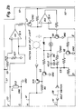
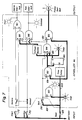
- Figures 2a, 2b, 2c and 2d are schematic views showing the electrical circuit controlling the operation of the starter and hydraulic interlocks in conjunction with the actuation of the seat switch and seat belt switch;
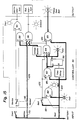
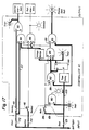
- Figures 2e and 2f are schematic views showing alternative embodiments of a portion of the electrical circuit corresponding to Figures 2a and 2b, the complete schematic view of the alternative electrical circuit comprises Figures 2e, 2f, 2c and 2d in the same arrangement shown in Figure 2, with Figure 2e replacing Figure 2a and Figure 2f replacing Figure 2b;
- Figure 3 is a side elevational view of the skid steer loader shown in Figure 1 with a hydraulically actuated movement of the working tool apparatus being shown in phantom;
- Figure 4 is an enlarged detail view of the seat belt forming the operator restraint mechanism corresponding to the circle labelled 4 in Figure 1 to show the location and actuation of the seat belt switch;
- Figure 4a is a cross-sectional view of a female receptor portion of the seat belt taken along lines 4a-4a of Figure 4;
- Figure 5 is a schematic diagram of a portion of the hydraulic and electrical circuits of the skid steer loader showing the hydraulic solenoid valves as pertain to the present invention; and
- Figures 6 - 18 are schematic logic diagrams showing the operation of the controller for the starter and hydraulic interlocks operating in conjunction with various combinations of switch actuations, the use of the heavy line along the logic circuit indicating the path of the generated signal.
- Referring now to the drawings, an industrial implement, commonly referred to as a skid steer loader, incorporating the principals of the instant invention can be seen. Any "left" and "right" references are used as a matter of convenience and are determined by standing at the rear of the machine facing the forward end at which is operably mounted a working tool. The drawings will be described in three distinct groupings, Figures 1 and 3-5 showing the mechanical structure of the implement, Figures 2 and 2a-d showing the electrical circuit of the controller, and Figures 6 - 18 depicting the logic of the controller operation.
- Referring now to Figures 1 and 3-5, the mechanical structure of the skid steer loader can best be seen. The
loader 10 is provided with aframe 12 havingwheels 13 mounted thereon mobilely to support theloader 10 over the ground G. Anengine 14 is mounted on theframe 12 and serves as the power plant for driving theloader 10 and theworking tool assembly 15. Although the present invention is not limited thereby, the means of propulsion is of conventional nature such as described in US-A-3,810,517. Theengine 14 is also of a conventional nature and includes a conventional starter mechanism (not shown) connected to the electrical system of theloader 10, as will be described in greater detail below, to effect a starting of theengine 14. - The
working tool assembly 15 is movably mounted on theframe 12 to perform a variety of working tasks typically associated with such implements. Theworking tool assembly 15 depicted in Figures 1 and 3 includes abucket 16 pivotally mounted on a pair of transversely-spacedboom arms 17 which are in turn pivotally connected to theframe 12. A pair of buckethydraulic cylinders 18 interconnect thebucket 16 andrespective boom arms 17 to provide a means for pivotally moving thebucket 16 relative to theboom arms 17. Similarly, a pair of boomhydraulic cylinders 19 interconnect therespective boom arms 17 and theframe 12 to provide pivotal movement of theboom arms 17 relative to theframe 12. - The
frame 12 supports anoperator compartment 20 forwardly of theengine 14 and immediately rearwardly of thebucket 16 to permit a view of the operation thereof. Theoperator compartment 20 is provided with anoperator seat 22 from which the operator can control the movements of theloader 10 and theworking tool assembly 15 by means ofcontrol levers 21 and/or pedal controls (not shown) in a conventional manner. Theseat 22 is equipped with aseat switch 23 operable to sense the presence of the operator in theseat 22 in a manner described in detail in US-A-4,385,863, the descriptive portions thereof being incorporated herein by reference. - The
operator compartment 20 is also provided with anoperator restraint mechanism 25 in the form of a seat belt as can be seen in greater detail in Figure 4a. Afemale receptor portion 27 of theseat belt 25 is provided with abelt switch 28 having acontact lever 29 positioned for engagement with amale buckle portion 26 of theseat belt 25 such that connection of themale buckle portion 26 with thefemale receptor portion 27 actuates thebelt switch 28 to sense the engagement of theoperator restraint mechanism 25 in an operative position in which theseat belt 25 may be wrapped around the operator to restrain him in theseat 22. When theoperator restraint mechanism 25 is in an inoperative position, i.e. disengaged, thebelt switch 28 will be open to prevent the passage of current therethrough, which will be described in greater detail below. - The
lower part 27a of thefemale receptor portion 27 is deepened over that previously known in the art to accommodate the depth of a sealedseat switch 28, such as the Cherry Waterproof Subminiature Snap Action Switch, Model DC. The sealedswitch 28 is fastened into place in the interior of thefemale receptor portion 27 by a pair ofpins 28a extending through the sealedswitch 28 and then secured, such as by gluing, to theoutside wall 27b of thefemale receptor portion 27 and to an internal reinforcingweb flange 27c, fixing the sealedswitch 28 therebetween. - The
contact lever 29 has acurved camming portion 29a to facilitate actuation thereof by the insertion of themale buckle portion 26 into engagement with thefemale receptor portion 27. The use of a sealedswitch 28 eliminates the problems of dirt fouling the contacts of standard microswitches to increase the performance and reliability characteristics of theoperator restraint mechanism 25. - Referring now to Figure 5, the
hydraulic system 30 for powering thehydraulic actuators hydraulic system 30 includes apump 32 operably driven from theengine 14 to provide fluid under pressure from thereservoir 33 throughout theconduits 36, 38 interconnecting thepump 32 and thehydraulic actuators conventional control valve 34 controls the direction of fluid from thepump 32 throughout theconduits 36, 38, thereby operably controlling the movement of thehydraulic cylinders working tool assembly 15. The conduit 36 interconnecting thecontrol valve 34 and the boomhydraulic cylinders 19 is provided with ahydraulic solenoid valve 37 which is operable to block the flow of fluid through the conduit 36 and thereby disable the operation of the boomhydraulic cylinders 19. Similarly, theconduit 38 interconnecting the buckethydraulic cylinders 18 and thecontrol valve 34 is also provided with ahydraulic solenoid valve 39 operable to block the flow of fluid through theconduit 38 and disable the operation of the buckethydraulic cylinders 18. - The
solenoid valves solenoid valves hydraulic system 30 will be enabled which will permit theworking tool assembly 15 to be operated. Without being energised, thesolenoid valves hydraulic system 30 in a disabled condition, locking up the operation of theworking tool assembly 15. One skilled in the art will readily realise that Figure 5 includes a schematic representation of the electrical system with current coming from the battery B and the energising control coming from theelectrical system 40 forming the controller described in greater detail with respect to Figure 2a below. - Referring now to Figures 2 and 2a-d, the
electrical circuit 40 forming the controller of theboom solenoid valve 37, thebucket solenoid valve 39 and the starter relay for theengine 14 can best be seen. Under initial conditions, the voltage from the battery VBAT is supplied throughterminal connection 42 and throughline 43 to relay contacts K2-1, K1-1, K4-1, K3-1 and to theopen seat switch 23. Since neither the open seat switch nor the relay contacts draw any load from the battery B, thecontroller 40 will stay in this inactive state without weakening the battery B. At the initial conditions with theengine 14 off, theseat switch 23 and thebelt switch 28 are open, theservice override switch 45 is open drawing the interconnectednormal operation switch 46 into its closed position, all the relay coils, K1, K2, K3, K4 and K5 are off and relay contacts K1-1, K2-1, K3-1, K4-1, K5-1, K2-2, and K5-2 are open, while relay contacts K1-2 and K2-3 are normally closed. - To awaken the
controller 40, the operator sits in theseat 22, closing theseat switch 23 which provides voltage vialine 47 to the collector of Ultra-Reliable transistor IC3 and through resistor R5 to the base of IC3. Since the NPN transistor Q5 is off, by reason of no current path to its base, the voltage on the base of transistor IC3 turns it on to illuminate the fasten seat belt light. Voltage is also applied byline 49 to the relay coil K1 and to the emitter of PNP transistor Q3. With theseat belt switch 28 open, the base of transistor Q3 is pulled down by resistor R9 through relay contacts K2-3, turning transistor Q3 on thereby supplying current to the base of NPN transistor Q1 and turning on transistor Q1 to energise relay coil K1. Voltage is also supplied vialine 51 to the negative input terminal of a comparator A. - Energising the relay coil K1 closes relay contact K1-1 and opens contact K1-2. The opening of contact K1-2 prevents voltage from reaching relay coil K5 and thereby prevents relay coils K3 and K4 from being energised. The closing of relay contact K1-1 supplies voltage to the power terminal of IC4 enabling comparators AA, BB, and CC and enabling oscillator amplifier DD. In addition, the closing of contact K1-1 supplies voltage to the input of the voltage regulator IC1 which provides five volts to the power terminal of IC2 enabling comparators A and B. The five volts from the voltage regulator IC1 is also applied to a divider formed by resistors R18 and R19 via
line 53 to make a 2.5 volt reference. The closing of relay contact K1-1 also supplies voltage vialine 55 to relay coil K2 and vialines - The divider formed by resistors R25 and R27, and comparators AA and BB provide the function of a voltage monitor. Resistors R25 and R27 are sized to provide greater than five volts to the positive terminal of comparator AA whenever the voltage in
line 57 is greater than 17 volts. Whenever the voltage of the positive terminal of the comparator AA is greater than 5 volts which is supplied to the negative terminal of comparator AA, the comparator AA outputs source current into the base of transistor Q7 which turns on, pulling the positive input terminal of comparator BB to ground, which in effect turns comparator BB off and pulls the base of transistor Q6 to ground, preventing transistor Q6 from being turned on. With transistor Q6 turned off, relay coil K5 is prevented from being energising which in turn prevents relay coils K3 and K4 from being energised. - Under normal circumstances, the voltage from the divider formed by resistors R25 and R27 is less than five volts. The comparator AA output then pulls the base of transistor Q7 to ground, preventing transistor Q7 from turning on. This allows the five volts on
line 53 to be applied to the positive terminal of comparator BB which in turn outputs source current to the base of transistor Q6 to permit relay coil K5 to energise by the current applied thereto. - Closing relay contact K1-1 also supplies voltage via a
line 57 to the divider formed by resistors R22 and R24. The voltage from this divider and the voltage fed back by resistor R23 determines the trip threshold of an oscillator amplifier DD. As the voltage applied to the divider formed by resistors R22 and R24 increases, the amplitude of the signal at capacitor C6 also increases. The output of the amplifier DD is high when the charge on the capacitor C6 is lower than the voltage on the positive input of the amplifier DD. The capacitor C6 is then charged through resistor R21 until the voltage on it exceeds the voltage on the positive input of amplifier DD. The output of amplifier DD then goes low and discharges capacitor C6 until the voltage on it goes below the positive input on the amplifier DD. The resistor R23 causes voltage on the positive input of amplifier DD to be higher when the output of amplifier is high and lower when the output of amplifier DD is low. This feature provides the changes to the positive input of amplifier DD required for the oscillator to oscillate and also determines the magnitude of the charge on the capacitor C6. - When five volts is applied to the positive input of comparator BB, the time that the signal at capacitor C6 is greater than five volts will cause the output of comparator BB to pull the base of transistor Q6 to ground, turning transistor Q6 off. The time that the signal at capacitor C6 is less than five volts will cause the output of comparator BB to apply current to the base of transistor Q6, turning transistor Q6 on. The ratio of time on to time off controls the current that can flow through relay coil K5. This current control permits operating relay control relay K5 over a wider voltage range without burnout caused by excessive current or lowered pull-in/hold-on force caused by too little current.
- Comparator CC performs the same function for transistor Q4 and relay coil K2 and for transistors Q2, Q3 and Q1 and relay coil K1. When relay contact K1-1 closes, the 2.5 volt reference is compared to the voltage at the negative input of comparator A. If the voltage on the negative input is greater than 2.5 volts, the output of comparator A turns on, shunting compacitor C3 and pulling the negative input of comparator B to ground. If the negative input of comparator B is lower than 2.5 volts, then the output of comparator B turns off allowing five volts to be applied to the positive input of comparator CC. With five volts supplied to the positive input of comparator CC, relay coil K2 is energised, closing relay contacts K2-1, K2-2 and opening relay contact K2-3. The opening of relay contact K2-3 removes resistor R9 from the base of transistor Q3, which turns control of the current through relay coil K1 over to transistors Q1, Q3 and Q2 and to comparator CC as explained above.
- The closing of the
seat switch 23 provides current to thebelt switch 28 vialine 61. The closing of theseat belt switch 28 supplies voltage to the base of transistor Q3, which overrides the control from transistor Q2 and forces transistor Q3 to turn off, preventing current from reaching the base of transistor Q1. With transistor Q1 turned off, relay coil K1 is deenergised, causing relay contacts K1-1 to open, but since relay coil K2 is energised, relay contact K2-1 provides voltage in the same manner as described above for relay contact K1-1. The energising relay coil K1 also causes contact K1-2 to close. Current is then supplied through the closed contacts K2-2 and K1-2 to the base of transistor Q5, turning transistor Q5 on and pulling the base of transistor IC3 to ground, which turns off the transistor IC3 and the fasten seat belt light. - Voltage is also supplied through relay contacts K2-2 and K1-2 to the relay coil K5 and, if the voltage applied to the comparator AA as described above permits, transistor Q6 will permit relay coil K5 to energise. The energising of relay coil K5 closes relay contacts K5-1 and K5-2. The closed relay contact K5-2 allows the voltage from the starter switch VSTART to energise relay coil K3, which in turn closed relay contact K3-1 and allows the battery voltage VBAT to be applied to the starter relay and permit the starting of the
engine 14. Closed relay contact K5-1 allows the voltage from the ignition switch VIGN to energise relay coil K4, closing relay contact K4-1 which in turn allows the battery voltage VBAT to be applied to theboom solenoid valve 37 and thebucket solenoid valve 39, enabling their operation. - If the voltage applied to the negative input of comparator AA increases above five volts, the current to the base of transistor Q6 will cease causing relay coil K5 to be deenergised, opening relay contacts K5-1 and K5-2. The opening of relay contact K5-1 will deenergise the relay coil K4, causing relay contact K4-1 to open and interrupt voltage to the
hydraulic solenoid valves engine 14, the closing of contact K3-1 will not turn off theengine 14 if it is already running. - If the
belt switch 28 is opened, control of transistor Q3 will be returned to transistor Q2 and comparactor CC, which if theseat switch 23 is still closed, turns on transistor Q1 as described above, energising relay coil K1, causing relay contact K1-2 to open, which in turn removes voltage from relay coil K5, opens relay contacts K5-1 and K5-2, and causes the results as described above. Since the opening of theseat belt switch 28 will also turn off transistor Q5, transistor IC3 is permitted to turn on and illuminate the fasten seat belt light. A reclosing of theseat belt switch 28 performs the same functions as the initial closing of theseat belt switch 28 as described above. - The opening of the
seat switch 23 removes voltage from the negative input of comparator A, allowing resistor R15 to pull the negative input of comparator A low, turning off the output of comparator A. With the output of comparator A off, the capacitor C3 is permitted to charge through resistor R17 toward the five volts carried byline 53. When the voltage on capacitor C3 reaches 2.5 volts, the output of comparator B will turn on, pulling the positive input of comparator CC to ground, which turns the output of comparator CC on to pull the bases of transistors Q4 and Q2 to ground, and turns transistors Q4 and Q2 off to deenergise relay coil K1 and K2. This situation will return the circuit to the initial conditions of power off described above. If, however, theseat switch 23 is reclosed before the voltage on the capacitor C3 reaches 2.5 volts, the output comparator A will be turned on removing the charge from C3 and permitting resumption of the normal operation as described above. The charging of capacitor C3 upon the opening of theseat switch 23 provides a delay for a period of time equal to approximately three seconds for theseat switch 23 to be reclosed without requiring a resequencing of the closing of theseat switch 23 and theseat belt switch 28. - If the
seat belt switch 28 is closed before theseat switch 23 is closed, the current supplied intoline 63 will prevent transistor Q3 from turning on, by reason of a lack of voltage differential between the base and the emitter of transistor Q3, preventing transistor Q1 from being turned on and energising relay coil K1. Since relay contact K1-1 and K2-1 remain open, current will not be supplied alongline 55 andline 53 to effect an energising of relay coil K2, keeping relay contacts K2-1 and K2-2 open and preventing relay coil K5 from being energised. As a result, relay contact K5-1 and K5-2 will remain open to prevent relay coils K3 and K4 from being energised, thereby disabling thehydraulic solenoid valves - The
controller 40 can be placed into a service mode by moving aservice switch 45 into a closed position which, because of the interconnection between theservice switch 45 and anormal operation switch 46, moves thenormal operation switch 46 into an open position. With theservice switch 45 closed, the voltage from the start VSTART will bypass the relay contact K5-2 and energise the relay coil K3 allowing the voltage from the battery VBAT to be supplied to the starter relay over the closed relay contact K3-1 and permit theengine 14 to be started. The opennormal operation switch 46 will prevent the relay coil K4 from being energised, keeping relay contact K4 open and preventing the voltage from the battery VBAT from being supplied to thehydraulic solenoids - Referring now to Figures 2e and 2f, an alternative configuration of the electrical circuit can be seen. One way to bypass the operation of the
seat switch 23 is to hard wire a jumper line across theswitch 23 so that the circuit never sees theseat switch 23 open when the operator leaves the seat. By placing a pair of diodes D2 and D3 within theseat switch 23, a voltage drop of approximately 1.2 volts can be realised across theswitch 23. Any attempt to hard wire a jumper line across theswitch 23 would take the diodes D2 and D3 out of the circuit and, therefore, prevent the voltage drop from being realised. - Current coming from the
switch 23 over aline 47 passes through the divider formed by resistors R25 and R27 to the positive terminal of comparator AA. Current passing throughline 48 due to the closing of relay contacts K1-1 and K2-1 is limited in voltage to a base reference 6.4 volts by the Zener Diode ZD1 and is fed to the negative terminal of comparator AA. The diode D1 inline 48 provides a reverse current protection, while the resistor R31 provides current protection for the Zener Diode ZD1. - The resultant operation of the comparator AA is similar to that noted above. If the voltage at the positive terminal is greater than the voltage at the negative terminal, the comparator AA will output source current to the base of transistor Q7, turning transistor Q7 on, which as noted above with respect to Figures 2a and 2b, turns the entire system off. Under normal circumstances, the divider formed by resistors R25 and R27 is sized such that the voltage through
line 47 to the positive terminal of comparator AA is always less than the voltage throughline 48 to the negative terminal because of the voltage drop caused by the diodes D2 and D3. If theseat switch 23 is bypassed, taking the diodes D2 and D3 out of the circuit, the voltage at the positive terminal of comparator AA will be greater than the reference voltage at the negative terminal, causing the system to turn off. - Similarly, a voltage surge in the circuit will cause a higher than normal voltage through
line 47 to the positive terminal of comparator AA, while the voltage at the negative terminal remains at the base reference due to the Zener Diode ZD1, again shutting the system down as noted above. Accordingly, the alternative configuration of Figures 2e and 2f provides both a voltage protection feature for the entire circuit and an anti-bypass feature for theseat switch 23. - Referring now to Figures 6-18, the logic operation of the
controller 40 can best be seen. The use of heavy lines in the logic diagrams in Figures 6-18 indicates the signal path. Figure 6 depicts the initial state of thecontroller 40 with current from the battery being supplied to theseat switch 23, anignition switch 70, and astarter switch 72. Thenormal operation switch 46 is in a closed position forcing the interconnectedservice override switch 45 into an open position. Theseat belt switch 28 is also open. The logic diagram includes six ANDgates OR gate 90, and a Set/Reset Latch 95, the operation which will be described in greater detail below. Thecontroller 40 is also provided with diagnostic lights indicating the operation of the seat switch, belt switch and timer, as well as diagnostic lights indicating operation of the hydraulic solenoid interlocks and the start relay interlock. Asignal inverter 89 is provided on three of the terminals and ANDgates solenoid valves loader 10. - Figure 7 depicts the manner in which the
controller 40 is awakened. The operator sits in the seat, closing theseat switch 23, to provide a signal alonglead 101 to theopen belt switch 28 and alonglead 103 to provide a signal to the b terminal of ANDgate 80, a signal to the b terminal of ANDgate 82, and a signal to the b terminal of ANDgate 85. The closing of theseat switch 23 also illuminates the diagnostic seat light and sets the time delay. Since ANDgate 80 reads only one signal at its two terminals, the belt diagnostic light remains unlit. Because of thesignal inverter 89, the ANDgate 82 reads a signal at both the a and b terminals and outputs a signal to the b terminal of ANDgate 84 and to the set terminal S of the Set/Reset Latch 95. - The activation of the Set/
Reset Latch 95 provides on the output of a signal from the Q terminal to illuminate the timer light, provide a signal to the c terminal of ANDgate 84, provide a signal through the voltage monitor to the b terminal of ANDgate 88 and the b terminal of ANDgate 86. Since the ANDgate 84 is reading no signal at its a and b terminals (due to the signal inverter 89), ANDgate 84 has no output. Likewise, the lack of signal at the a and c terminals at ANDgate signal inverter 89 at the a terminal of the ANDgate 85, a signal is recognised at both the a and b terminal of ANDgate 85, resulting in an output to illuminate the fasten seat belt light externally of thecontroller 40. As a result, the operator is informed that he must fasten his seat belt to enable operation of the loader. - The next sequential step is reflected in Figure 8. After sitting in the seat, closing the
seat switch 23 as reflected in Figure 7, the operator fastens his seat belt, closing thebelt switch 28. The signal crosses theclosed belt switch 28 fromlead 101 to lead 105 to provide a signal to the a terminal of ANDgate 80, the a terminal of ANDgate 82, and the a terminal of the ANDgate 84. Since ANDgate 80 now receives a signal at both the a and b terminals, the output signal illuminates the diagnostic belt light. The receipt of a signal at the a terminal of ANDgate 82 is inverted by thesignal inverter 89, resulting in a cancellation of the output signal from ANDgate 82. - Since the Set/
Reset Latch 95 has been turned on by the closing of theseat switch 23, the signal continues from the Q terminal to illuminate the timer diagnostic light and to provide a signal at the c terminal of ANDgate 84 and the b terminals of ANDgates signal inverter 89 at the b terminal, ANDgate 84 reads a signal at all three terminals and outputs a signal to the a terminal of ANDgate 85 and the c terminals of ANDgate signal inverter 89 at the a terminal of ANDgate 85 effects a cancellation of the output of ANDgate 85 to turn off the fasten seat belt light externally of the controller. Since ANDgates gates - After the proper sequencing of the closing of the
seat switch 23 and thebelt switch 28 as reflected in Figures 7 and 8, the operator can enable operation of theloader 10 by closing the ignition and starter switches 70, 72 as reflected in Figure 9. The signal from theclosed ignition switch 70 passes through the closednormal operation switch 46 and enters the a terminal of ANDgate 86. Since ANDgate 86 now reads a signal at all three of its input terminals, the output signal illuminates the solenoid diagnostic light and activates the hydraulic interlock in the form of energising thesolenoid valves hydraulic system 30 as described above. The signal from theclosed starter switch 72 bypasses the open service override switch vialead 107 to provide a signal at the a terminal of ANDgate 88. Since all three input terminals of ANDgate 88 have a signal provided thereto, the output signal from ANDgate 88 goes to the b terminal ofOR gate 90, activating the output signal to illuminate the start diagnostic light and energise the starter relay interlock which in turn permits the starting of theengine 14. - Once the
engine 14 has been started and thestarter switch 72 opened, as reflected in Figure 10, theclosed ignition switch 70 continues the activation of ANDgate 86 to energise the hydraulic interlock and permit the continued operation of theloader 10 with theengine 14 running. It should be clear from reference to Figure 9 and 10 that the mere stopping of theengine 14 without changing the condition of theswitches switch 72 will provide a reenergising of the starting interlock to permit a restarting of theengine 14. Figure 10 reflects logic operation of the controller corresponding to the normal operative mode of theloader 10. - Under some rough operating conditions, the operator could conceivably be bouncing somewhat in his seat, opening and closing the
seat switch 23 repeatedly. This condition is reflected in Figures 11 and 12. Figure 11 depicts the logic operation when the operator is bounced up in the seat, opening theseat switch 23. The opening ofseat switch 23 terminates the signal along leads 101, 103 and 105, directly shutting off ANDgates seat switch 23 has remained open for less than 3 seconds, the time delay will not have actuated, leaving the Set/Reset Latch outputting a signal from its Q terminal to illuminate the time diagnostic light and provide a signal from a voltage monitor to the b terminals of ANDgates lead 105 to the a terminal of ANDgate 84 prevents the output of signal to the c terminal of ANDgate 86, the output of ANDgate 86 has been turned off, deenergising the hydraulic interlock to prevent operation of the loaderhydraulic system 30. It can be seen that the result of opening theseat switch 23 is a locking up of the loader hydraulics and a disabling of the boom and bucket. - Figure 12 depicts the operator reexerting his weight upon the seat, closing the
seat switch 23, the signal is reinstated along leads 101, 103 and 105 in the same manner as reflected in Figure 10 to reenergise the hydraulic interlock and enable the operation of the boom and bucket controls. Figure 13 reflects the logic operation for the alternative condition, the lack of presence of the operator in the seat, i.e. leaving theseat switch 23 open, for a period of time greater than three seconds. After three seconds of a continuous opening of theswitch 23, the time delay is activated sending a signal to the reset terminal R of the Set/Reset Latch 95 turning off the Set/Reset Latch 95 and eliminating the signal from the Q terminal, which in turn eliminates a signal through the voltage monitor to the b terminals of ANDgates - Figures 13 and 14 can be referred to as the anti-tie-down feature. It is possible for the operator to bypass the logics of the controller as reflected in Figures 7 and 8 by sitting in the seat and fastening the seat belt behind the operator. As soon as the operator leaves his seat, as reflected in Figure 11, the hydraulic interlock is deenergised preventing operation of the boom and bucket controls. Irrespective of the condition of the
belt switch 28. If the operator has exited theloader 10 leaving the engine running and the seat belt fastened for a period of time greater than three seconds, the operator will find that he must resequence the closing of theseat switch 23 and thebelt switch 28 to enable operation of the hydraulically actuated boom and bucket. - Figure 14 reflects the logic operation following the scenario set forth in the preceding paragraph. The operator who has been absent from his seat for a period of time greater than three seconds returns to the seat closing the
seat switch 23. The resulting signal along leads 101, 103 and 105 and the already closedbelt switch 28 illuminates the seat diagnostic light, activates ANDgate 80 to illuminate the belt diagnostic light, recharges the time delay and provides a signal to the b terminal of ANDgate 85, the a and b terminal of ANDgate 82 and the a terminal of ANDgate 84. Because of thesignal inverter 89 at the a terminal of ANDgate 82, the ANDgate 82 reads only a signal at the b terminal and does not output a signal to the set terminal S of the Set/Reset Latch 95 or to the b terminal of ANDgate 84. - Since the Set/
Reset Latch 95 had been turned off by the activation of the time delay, as reflected in Figure 13, no signal will be transmitted from the Q terminal of the Set/Reset Latch 95 to illuminate the timer diagnostic light or provide a signal to the c terminal of ANDgate 84 or through the voltage monitor to the b terminals of ANDgates gate 84 does not receive a signal at its c terminal, the lack of output from ANDgate 84 prevents a signal from being received by terminal a of ANDgate 85 and terminal c of ANDgate signal inverter 89 at the a terminal of ANDgate 85 causes ANDgate 85 to read a signal at both the a and b terminals and, therefor, output a signal to illuminate the fasten seat belt light externally of the controller. Since ANDgate 86 is not receiving a signal at either the b or c terminals, the hydraulic interlock is not energised and the boom and bucket controls remain inoperative. - It can be seen, therefore, that merely reclosing the
seat switch 23 by sitting back down in the seat will not enable the operation of the boom and bucket. By illuminating the fasten seat belt light, the controller is telling the operator that he must resequence to enable operation of the loader. If thebelt switch 28 is not closed immediately subsequent to the closing of theseat switch 23, i.e. the closing of thebelt switch 28 must occur before the operator has left theseat 22 for a period of time greater than the predetermined period for the time delay to turn off the Set/Reset Latch 95, the operator will have to resequence the closing of theseat switch 23 and thebelt switch 28. - Figure 15 depicts the subsequent operation to that described above with respect to Figure 14, an unfastening of the seat belt and an opening of the
seat belt switch 28. Removing the signal fromlead 105 by the opening of thebelt switch 28 removes the inverted signal from the a terminal of ANDgate 82. The resultant output of ANDgate 82 provides a signal to the inverted b terminal of ANDgate 84 and to the set terminal S of the Set/Reset Latch 95. As described above with respect to Figure 7, the output signal from terminal Q of the Set/Reset Latch 95 turns on the timer diagnostic light and provides a signal to the b terminals of ANDgates belt switch 28 provides a signal identical to that described above with respect to Figure 8, turning off the fasten seat belt light and, since theignition switch 70 and thenormal operation switch 46 has already been closed, providing a signal to the a terminal of ANDgate 86, the logic operation will be identical to that described above with respect to Figure 10, energising the hydraulic interlock and enabling the operation of the boom and bucket controls. - The controller also provides a service override feature depicted in Figure 16. A closing of the
service override switch 45, resulting in an opening of thenormal operation switch 46, provides a signal directly to the a terminal of theOR gate 90, the output of which illuminates the start diagnostic light and energises the starter relay interlock. The service override feature permits the starting and running of theengine 14; however, the hydraulic interlock cannot be energised to enable operation of the workingtool assembly 15. The closing of theseat switch 23 while the service override switch is closed, as reflected in Figure 17, provides a signal along leads 101 and 103 in a manner similar to that described above with respect to Figure 7. A subsequent closing of the seat belt andbelt switch 28 with theservice override switch 45 closed, as reflected in Figure 18, will still not energise the hydraulic interlock. Although the signal path resulting from the closing of thebelt switch 28 is similar to that described above with respect to Figure 8, the lack of signal alonglead 109, due to the opennormal operation switch 46, to the a terminal of ANDgate 86 prevents the ANDgate 86 from outputting a signal energising the hydraulic interlock. - Referring again to Figure 17, it can be seen that the controller logic cannot be bypassed merely by starting the
engine 14 using theservice override switch 45, sitting in theseat 22 without buckling theseat belt 25, and then flipping thenormal operation switch 46, because no signal is received at the c terminal of ANDgate 86 to permit an enabling of the hydraulic interlock. Similarly to the logic shown in Figure 14, if the operator first buckles theseat belt 25 and then sits in theseat 22, no signal would be sent to the b terminal of ANDgate 86, thereby disabling thehydraulic system 30. Although it is possible to bypass the logic of this particular controller, as described above with respect to Figures 7 - 9 and Figures 11 - 15, any time the operator leaves his seat for a period of time greater than approximately three seconds, he will have to unfasten and refasten theseat belt 25 to effect a resequencing of the closing of theseat switch 23 and thebelt switch 28 to enable the operation of the workingtool apparatus 15. Accordingly, it is expected to be more convenient and easier to comply with the controller logic than it is continually to try to bypass the logic.
Claims (18)
- An implement comprising a mobile frame (12); an operator station (20) mounted on the frame and including a seat (22) in which the operator sits during the operation of the implement; working means (15) movably supported on the frame for performing tasks controlled by the operator from the seat; actuator means (18,19) operably associated with the working means for selectively effecting movement of the working means relative to the frame; power means (14) supported on the frame and operable to power the actuator means and effect movement of the implement; first sensing means (23) operatively connected to the seat (22) to sense the presence of the operator in the seat; and controller means (40) operatively associated with the first sensing means (23) and the power means (14) for disabling the actuator means if the operator leaves his seat for longer than a predetermined period of time, characterised in that the implement further comprises an operator restraint mechanism (25) having an operative position in which the operator restraint mechanism is operable to keep the operator in the seat, and an inoperative position in which the operator is not restrained on the seat; second sensing means (28) operatively connected to the operator restraint mechanism (25) to sense the placement of the operator restraint mechanism in the operative position, the controller (40) being operatively associated with the second sensing means (28) and operable to disable the starting of the power means (14) unless the first and second sensors are actuated in a predetermined sequence, the controller means being further operably associated with the actuator means (18,19) for disabling the operation of the actuator means when the operator restraint mechanism is moved from the operative to the inoperative position when the power means is enabled, the controller preventing the reenabling of the actuator means unless the first and second sensing means are actuated in said predetermined sequence.
- An implement according to claim 1, wherein the power means comprises an engine (14) which is operably started in conjunction with the closing of an electrical circuit, the controller means (40) being operably connected to the electrical circuit to keep the electrical circuit open, thereby disabling the starting of the engine, unless the first and second sensing means (23,28) are actuated in said predetermined sequence.
- An implement according to claim 1 or 2, wherein the predetermined sequence of actuation of the first and second sensing means (23,28) comprises first sensing the presence of the operator in the seat (22) and then sensing the movement of the operator restraint mechanism (25) from the inoperative position to the operative position.
- An implement according to any of the preceding claims and further comprising delay means operably associated with the first sensing means (23) for delaying for a predetermined period of time the operative receipt by the controller means (40) of a signal representative of deactuation of the first sensing means to indicate that the operator has left the seat (22).
- An implement according to claim 4, wherein the controller means (40) requires said predetermining sequence of actuation of the first and second sensing means (23,28) after the operative receipt of the deactuation of the first sensing means (23) indicating that the operator has left the seat (22) before the controller means will enable the actuator means (45,46,70,72) unless the first sensing means (23) is reactuated to indicate the presence of the operator in the seat (22).
- An implement according to claim 5, wherein the actuator means includes hydraulic cylinders (18,19) connected to a pressurised hydraulic circuit operably powered by the power means (14), the hydraulic circuit including a hydraulic solenoid valve (37,39) operable selectively to block the flow of hydraulic fluid through the hydraulic circuit to the hydraulic cylinders and thereby disable the hydraulic cylinders.
- An implement according to claim 6, wherein the controller means (40) is operably connected to the hydraulic solenoid valve (37,39) for selective actuation thereof to disable the actuator means (18,19).
- An implement according to any of claims 5 to 7, when appended to claim 2, wherein the controller means (40) is operably connected to said electrical circuit to close the electrical circuit only upon receipt of the actuation of the second sensing means (28) indicating the operator restraint mechanism has been moved into the operative position after receipt of the actuation of the first sensing means (23) indicating the presence of the operator in the seat (22), but before receipt of any reactuation of the first sensing means indicating the operator has left the seat.
- An implement according to any of the preceding claims, wherein the first sensing means (23) includes anti-bypass means (80,82,84,85,89) associated with the controller means (40) for sensing if the first sensing means (23) has been bypassed and for subsequently disabling the operation of the implement.
- An implement according to claim 9, wherein the controller means (40) includes an electrical circuit connected to the first and second sensing means (23,28), the anti-bypass means effecting a voltage drop at the first sensing means (23), and the electrical circuit including a comparator (84) operable to effect a disabling of the implement when the voltage drop is not encountered.
- An implement according to claim 6, wherein the first sensing means (23) is operatively connected to the hydraulic solenoid valve such that deactuation of the first sensing means actuates the hydraulic solenoid valve to disable the working means (15).
- An implement according to claim 2, or any of claims 3 to 11 when appended thereto, wherein the seat switch (23) includes a means for effecting a voltage drop for current passing therethrough from the electrical circuit, the controller means (40) being operable to disable the starting of the engine (14) by keeping the electrical circuit open unless the voltage drop is encountered.
- An implement according to any of the preceding claims, wherein the controller means (40) is operable to disable the starting of the power means unless actuation of the second sensor means (28) is notified to the controller means immediately subsequent to the notification of actuation of the first sensor means (23).
- An implement according to claim 13, wherein the first sensor means (23) generates an inverse first signal when the operator leaves the seat (22), the controller means (40) disabling the actuator means (18,19) upon the generation of said inverse first signal and requiring a resequencing of the notification of the actuation of the first and second sensor means (23,28) before enabling the actuator means after operatively receiving said inverse first signal.
- An implement according to claim 14, wherein the second sensor means (28) generates an inverse second signal when the operator restraint mechanism (25) is placed in the inoperative position, the controller means (40) disabling the actuator means (18,19) upon the generation of the inverse second signal and requiring a resequencing of the notification of the actuation of the first and second sensor means (23,28) before enabling the actuator means after receiving said inverse second signal.
- An implement according to any of the preceding claims, wherein the operator restraint mechanism comprises seat belt apparatus (25) which includes a female receptor portion (27) and a male buckle portion (26) engageable therewith in the closed position and separable therefrom in the open position; wherein a source of electrical current is supported on the frame; and wherein a sealed switch (28) is connected to the source of electrical current and has a pivotable contact lever (29) mounted in the female receptor portion (27) to be actuated upon engagement of the male buckle portion (26) with the female receptor portion and permit the flow of electrical current through the sealed switch for indicating the movement of the seat belt apparatus into the closed position.
- An implement according to claim 16, wherein the sealed switch (28) is mounted to the interior of the female receptor portion (27) by a pair of pins (28a) passing through the sealed switch and being secured to the female receptor portion.
- An implement according to claim 16 or 17, wherein the contact lever (29) has a curved camming portion engageable with the male buckle portion (26) to actuate the sealed switch (28).
Applications Claiming Priority (4)
| Application Number | Priority Date | Filing Date | Title |
|---|---|---|---|
| US154675 | 1980-05-30 | ||
| US15467588A | 1988-02-10 | 1988-02-10 | |
| US07/219,037 US4844196A (en) | 1988-02-10 | 1988-07-14 | Seat belt interlock for loaders |
| US219037 | 1988-07-14 |
Publications (2)
| Publication Number | Publication Date |
|---|---|
| EP0328341A1 EP0328341A1 (en) | 1989-08-16 |
| EP0328341B1 true EP0328341B1 (en) | 1992-09-02 |
Family
ID=26851662
Family Applications (1)
| Application Number | Title | Priority Date | Filing Date |
|---|---|---|---|
| EP89301156A Expired EP0328341B1 (en) | 1988-02-10 | 1989-02-07 | Seat belt interlock for loaders |
Country Status (4)
| Country | Link |
|---|---|
| US (1) | US4844196A (en) |
| EP (1) | EP0328341B1 (en) |
| CA (1) | CA1309994C (en) |
| DE (1) | DE68902653T2 (en) |
Families Citing this family (17)
| Publication number | Priority date | Publication date | Assignee | Title |
|---|---|---|---|---|
| US5120980A (en) * | 1990-05-08 | 1992-06-09 | Fontaine Brake Company | Seat cushion switch with delay circuit |
| US5425431A (en) * | 1994-02-18 | 1995-06-20 | Clark Equipment Company | Interlock control system for power machine |
| US5542493A (en) * | 1994-02-22 | 1996-08-06 | Clark Equipment Company | Hall effect sensor assembly |
| US5577876A (en) * | 1994-02-22 | 1996-11-26 | Clark Equipment Company | Hydraulic interblock system |
| US5547039A (en) * | 1994-11-25 | 1996-08-20 | New Holland North America, Inc. | Security and safety interlocks for a loader |
| US5565829A (en) * | 1995-04-06 | 1996-10-15 | Clark Equipment Company | Side pivot seat |
| US5711391A (en) * | 1996-06-17 | 1998-01-27 | Clark Equipment Company | Auxiliary interlock control system for power machine |
| US5883441A (en) * | 1997-06-20 | 1999-03-16 | Deere & Company | Seat and seat belt sequence circuit |
| KR19990086382A (en) * | 1998-05-27 | 1999-12-15 | 토니헬샴 | Heavy Duty Vehicle Work Device Control System |
| US6062331A (en) * | 1998-10-09 | 2000-05-16 | S.A.R.L. | Auxiliary hydraulic control system for a work machine |
| US6186260B1 (en) | 1998-10-09 | 2001-02-13 | Caterpillar S.A.R.L. | Arm rest/seat switch circuit configuration for use as an operational state sensor for a work machine |
| US6135230A (en) * | 1998-10-09 | 2000-10-24 | Caterpillar S.A.R.L. | Interlock control system for a work machine |
| US6189646B1 (en) | 1998-11-30 | 2001-02-20 | Clark Equipment Company | Traction lock/momentary override |
| DE10146627A1 (en) * | 2001-09-21 | 2003-04-10 | Still Gmbh | Industrial truck with a seat belt |
| DE102012014137A1 (en) * | 2012-07-18 | 2014-01-23 | Manfred Thaler | Driver seat safety device for open unclosed cabin, has control- and evaluation unit in operative connection with sensor in buckle in seat, where sensor is provided in buckle of seat belt with tempering apparatus or propulsion apparatus |
| EP2929772B1 (en) * | 2014-04-09 | 2016-11-23 | GGP Italy S.p.A. | Riding mower with control tamper apparatus |
| US10336292B2 (en) * | 2016-08-30 | 2019-07-02 | Clark Equipment Company | Seat belt |
Family Cites Families (11)
| Publication number | Priority date | Publication date | Assignee | Title |
|---|---|---|---|---|
| US3781479A (en) * | 1970-01-26 | 1973-12-25 | Lahr J | Method and apparatus for transmitting time compressed audio information |
| GB1430767A (en) * | 1972-04-29 | 1976-04-07 | Pektron Ltd | Seat belt interlock and warning system |
| US3876974A (en) * | 1972-07-31 | 1975-04-08 | Chrysler Corp | Vehicle safety belt sequence network |
| US4096468A (en) * | 1972-07-31 | 1978-06-20 | Chrysler Corporation | Solid state sequence logic circuit |
| DE2631849A1 (en) * | 1976-07-15 | 1978-01-19 | Agfa Gevaert Ag | RECORDING DEVICE |
| FR2414423A1 (en) * | 1978-01-17 | 1979-08-10 | Neiman Sa | DEVICE FOR LOCKING A MOTOR VEHICLE LOCK ON THE CLOSING OF A SEAT BELT |
| JPS5819494B2 (en) * | 1978-11-06 | 1983-04-18 | トヨタ自動車株式会社 | Passive seat belt device |
| US4385863A (en) * | 1981-05-13 | 1983-05-31 | Sperry Corporation | Seat interlock for skid-steer loader |
| US4389154A (en) * | 1981-05-13 | 1983-06-21 | Sperry Corporation | Time delay for a seat switch activated loader boom lock |
| US4678058A (en) * | 1986-04-07 | 1987-07-07 | Outboard Marine Corporation | Vehicle seat switch |
| US4699561A (en) * | 1986-05-08 | 1987-10-13 | J. I. Case Company | Engine interlock control system for a material handling implement |
-
1988
- 1988-07-14 US US07/219,037 patent/US4844196A/en not_active Expired - Fee Related
- 1988-11-30 CA CA000584520A patent/CA1309994C/en not_active Expired - Lifetime
-
1989
- 1989-02-07 EP EP89301156A patent/EP0328341B1/en not_active Expired
- 1989-02-07 DE DE8989301156T patent/DE68902653T2/en not_active Expired - Fee Related
Also Published As
| Publication number | Publication date |
|---|---|
| CA1309994C (en) | 1992-11-10 |
| US4844196A (en) | 1989-07-04 |
| EP0328341A1 (en) | 1989-08-16 |
| DE68902653T2 (en) | 1993-03-11 |
| DE68902653D1 (en) | 1992-10-08 |
Similar Documents
| Publication | Publication Date | Title |
|---|---|---|
| US4871044A (en) | Service override for loader interlock | |
| EP0328341B1 (en) | Seat belt interlock for loaders | |
| US4856612A (en) | Method of controlling the operation of a loader | |
| US6135230A (en) | Interlock control system for a work machine | |
| US7367256B2 (en) | Pressure switch control for attachment coupling system | |
| US7047866B2 (en) | Electrical and hydraulic control system for attachment coupling system | |
| JP2000120109A (en) | Remote controller for attachment for power machine | |
| JPH0285018A (en) | Auxiliary joint pressure relief hydraulic device | |
| JP4271685B2 (en) | Work vehicle and engine restart control method for work vehicle | |
| JP2001032332A (en) | Alarm device for construction machine | |
| JPH082447Y2 (en) | Operation control device for work vehicle | |
| JP3907581B2 (en) | Tractor engine control device | |
| WO2022059477A1 (en) | Work vehicle | |
| CA1097774A (en) | Engine air heater and starting circuits to by-pass auxiliary steering circuit | |
| JP7556812B2 (en) | Construction Machinery | |
| JPH07119182A (en) | Safety device for working machine | |
| JP2022151219A (en) | Construction machine | |
| JPH01101235A (en) | Device for controlling operations of boarding type work machine | |
| JP3101158B2 (en) | Cab-over vehicle step elevating device | |
| JPH0341070Y2 (en) | ||
| JP2525423B2 (en) | Passive seat belt device | |
| JPH0818791B2 (en) | Turning warning device for construction and cargo handling machines | |
| JPH078289Y2 (en) | Operation control device for passenger work equipment | |
| JP2933345B2 (en) | Protection device for electric actuator | |
| JPH0448132B2 (en) |
Legal Events
| Date | Code | Title | Description |
|---|---|---|---|
| PUAI | Public reference made under article 153(3) epc to a published international application that has entered the european phase |
Free format text: ORIGINAL CODE: 0009012 |
|
| AK | Designated contracting states |
Kind code of ref document: A1 Designated state(s): DE FR GB |
|
| 17P | Request for examination filed |
Effective date: 19900216 |
|
| 17Q | First examination report despatched |
Effective date: 19910328 |
|
| GRAA | (expected) grant |
Free format text: ORIGINAL CODE: 0009210 |
|
| AK | Designated contracting states |
Kind code of ref document: B1 Designated state(s): DE FR GB |
|
| REF | Corresponds to: |
Ref document number: 68902653 Country of ref document: DE Date of ref document: 19921008 |
|
| ET | Fr: translation filed | ||
| PLBE | No opposition filed within time limit |
Free format text: ORIGINAL CODE: 0009261 |
|
| STAA | Information on the status of an ep patent application or granted ep patent |
Free format text: STATUS: NO OPPOSITION FILED WITHIN TIME LIMIT |
|
| 26N | No opposition filed | ||
| REG | Reference to a national code |
Ref country code: GB Ref legal event code: IF02 |
|
| REG | Reference to a national code |
Ref country code: GB Ref legal event code: 732E |
|
| REG | Reference to a national code |
Ref country code: FR Ref legal event code: CD Ref country code: FR Ref legal event code: TP |
|
| PGFP | Annual fee paid to national office [announced via postgrant information from national office to epo] |
Ref country code: GB Payment date: 20060103 Year of fee payment: 18 |
|
| PGFP | Annual fee paid to national office [announced via postgrant information from national office to epo] |
Ref country code: FR Payment date: 20060110 Year of fee payment: 18 |
|
| PGFP | Annual fee paid to national office [announced via postgrant information from national office to epo] |
Ref country code: DE Payment date: 20060131 Year of fee payment: 18 |
|
| GBPC | Gb: european patent ceased through non-payment of renewal fee |
Effective date: 20070207 |
|
| REG | Reference to a national code |
Ref country code: FR Ref legal event code: ST Effective date: 20071030 |
|
| PG25 | Lapsed in a contracting state [announced via postgrant information from national office to epo] |
Ref country code: DE Free format text: LAPSE BECAUSE OF NON-PAYMENT OF DUE FEES Effective date: 20070901 |
|
| PG25 | Lapsed in a contracting state [announced via postgrant information from national office to epo] |
Ref country code: FR Free format text: LAPSE BECAUSE OF NON-PAYMENT OF DUE FEES Effective date: 20070228 Ref country code: GB Free format text: LAPSE BECAUSE OF NON-PAYMENT OF DUE FEES Effective date: 20070207 |