EP0324463B1 - Rohraufweitungsgerät - Google Patents
Rohraufweitungsgerät Download PDFInfo
- Publication number
- EP0324463B1 EP0324463B1 EP89100457A EP89100457A EP0324463B1 EP 0324463 B1 EP0324463 B1 EP 0324463B1 EP 89100457 A EP89100457 A EP 89100457A EP 89100457 A EP89100457 A EP 89100457A EP 0324463 B1 EP0324463 B1 EP 0324463B1
- Authority
- EP
- European Patent Office
- Prior art keywords
- pipe
- conical tip
- longitudinal axis
- cutting edge
- old
- Prior art date
- Legal status (The legal status is an assumption and is not a legal conclusion. Google has not performed a legal analysis and makes no representation as to the accuracy of the status listed.)
- Expired - Lifetime
Links
- 238000006073 displacement reaction Methods 0.000 claims abstract description 19
- 230000001681 protective effect Effects 0.000 claims abstract description 4
- 239000002184 metal Substances 0.000 claims abstract description 3
- 229910052751 metal Inorganic materials 0.000 claims abstract description 3
- 238000010276 construction Methods 0.000 description 3
- 230000002787 reinforcement Effects 0.000 description 3
- 239000002689 soil Substances 0.000 description 3
- 229910001018 Cast iron Inorganic materials 0.000 description 1
- 238000009412 basement excavation Methods 0.000 description 1
- 238000010009 beating Methods 0.000 description 1
- 230000000694 effects Effects 0.000 description 1
- 238000009434 installation Methods 0.000 description 1
- 239000000463 material Substances 0.000 description 1
Images
Classifications
-
- F—MECHANICAL ENGINEERING; LIGHTING; HEATING; WEAPONS; BLASTING
- F16—ENGINEERING ELEMENTS AND UNITS; GENERAL MEASURES FOR PRODUCING AND MAINTAINING EFFECTIVE FUNCTIONING OF MACHINES OR INSTALLATIONS; THERMAL INSULATION IN GENERAL
- F16L—PIPES; JOINTS OR FITTINGS FOR PIPES; SUPPORTS FOR PIPES, CABLES OR PROTECTIVE TUBING; MEANS FOR THERMAL INSULATION IN GENERAL
- F16L55/00—Devices or appurtenances for use in, or in connection with, pipes or pipe systems
- F16L55/16—Devices for covering leaks in pipes or hoses, e.g. hose-menders
- F16L55/162—Devices for covering leaks in pipes or hoses, e.g. hose-menders from inside the pipe
- F16L55/165—Devices for covering leaks in pipes or hoses, e.g. hose-menders from inside the pipe a pipe or flexible liner being inserted in the damaged section
- F16L55/1658—Devices for covering leaks in pipes or hoses, e.g. hose-menders from inside the pipe a pipe or flexible liner being inserted in the damaged section the old pipe being ruptured prior to insertion of a new pipe
-
- E—FIXED CONSTRUCTIONS
- E03—WATER SUPPLY; SEWERAGE
- E03F—SEWERS; CESSPOOLS
- E03F3/00—Sewer pipe-line systems
- E03F3/06—Methods of, or installations for, laying sewer pipes
-
- E—FIXED CONSTRUCTIONS
- E21—EARTH OR ROCK DRILLING; MINING
- E21B—EARTH OR ROCK DRILLING; OBTAINING OIL, GAS, WATER, SOLUBLE OR MELTABLE MATERIALS OR A SLURRY OF MINERALS FROM WELLS
- E21B7/00—Special methods or apparatus for drilling
- E21B7/28—Enlarging drilled holes, e.g. by counterboring
- E21B7/30—Enlarging drilled holes, e.g. by counterboring without earth removal
-
- E—FIXED CONSTRUCTIONS
- E03—WATER SUPPLY; SEWERAGE
- E03F—SEWERS; CESSPOOLS
- E03F3/00—Sewer pipe-line systems
- E03F3/06—Methods of, or installations for, laying sewer pipes
- E03F2003/065—Refurbishing of sewer pipes, e.g. by coating, lining
Definitions
- the invention relates to a pipe widening device for breaking up and pressing old metal pipes into the surrounding earth in the form of a cylindrical bottom displacement hammer to be pulled through the old pipe, provided with a conical tip and at least one cutting edge, with a vibrating hammering chisel head and a rear hanger device for a protective pipe to be pulled in or a new supply pipe .
- a pipe widening device for breaking up and pressing old metal pipes into the surrounding earth in the form of a cylindrical bottom displacement hammer to be pulled through the old pipe, provided with a conical tip and at least one cutting edge, with a vibrating hammering chisel head and a rear hanger device for a protective pipe to be pulled in or a new supply pipe .
- a pipe widening device for breaking up and pressing old metal pipes into the surrounding earth in the form of a cylindrical bottom displacement hammer to be pulled through the old pipe, provided with a conical tip and at least one cutting edge, with a vibrating hammer
- the invention is therefore based on the object of designing a pipe widening device of the type mentioned in such a way that an improved mounting of the soil displacement hammer and, as a result, an increased breaking force of the cutting tip is ensured.
- a knife with a cutting edge inclined to the longitudinal axis of the conical tip is opposite a support surface which is essentially parallel to the longitudinal axis and which merges into a short tear-open cutting edge at the rear end.
- the present invention is based on the knowledge gained by extensive tests that it is precisely the attempt to break open the pipe at two or more points at the same time
- the problems outlined above are largely caused by.
- Even with two symmetrical, opposing cutting edges there is not only the difficulty that only half the force required to break the tube is available on one cutting edge, but in particular a wedging effect is created which, like a self-locking wedge, further penetrates the soil displacement hammer excludes.
- Due to the support surface according to the invention which runs essentially parallel to the longitudinal axis of the ground displacement hammer, the force can be used completely to break up the pipe at a single point.
- the support surface parallel to the axis prevents self-locking of a wedge angle that is too large and, on the other hand, results in an increased frictional force, which prevents the vibrating bit head from springing back too much and thus really brings out its breaking force
- the support surface at the rear end merges into a short tear-open edge, which thus also tears the pipe that has already been torn open on the opposite side tears open, so that at least two half-tubes are available, which can be displaced much better to the outside.
- the tearing through the shortened backward-tearing tear-open blade is much easier and with less effort in view of the tube that has already been torn open on one side, precisely because the pre-expansion of the tubes, which are often made of cast iron, also causes a break on the side opposite the first tear seam occurred or at least is indicated in the structure.
- a particularly simple and effective construction of a pipe widening device according to the invention is obtained if, as is provided in the embodiment of the invention, a knife plate projecting forward over the conical tip is provided, which forms both the cutting edges and a supporting edge.
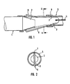
- the cylindrical ground displacement hammer 1 is provided with a conical tip 2, onto which a knife plate 3 is welded, which in turn is connected to a pull rope 4, which is of a construction pit from the ground displacement hammer, which has been inserted through a spaced construction pit, pulls through the old pipe 5.
- a vibrating impact device is provided, which is connected via compressed air supply lines at the rear end to a compressed air source arranged in the region of the rear excavation pit.
- a protective tube for a new supply pipe to be inserted later or the new supply pipe itself is attached to the rear end of the ground displacement hammer 1.
- the knife plate 3 is designed such that it has an inclined cutting edge 6 on one side, while on the opposite side there is a cutting edge 7 which is free of cutting edges and runs essentially parallel to the longitudinal axis of the ground displacement hammer and thus also of the old pipe. This merges into a short ripping edge 8 only at the rear end.
- This design ensures that, particularly in the area of special reinforcements of the old pipe, such as the sleeve 9 indicated above, in which practically twice the wall thickness of an old pipe has to be broken open, a break must first be achieved on one side and not, as in the case of previous ground displacement hammers, a simultaneous tearing on two or even more staggered edges.
- the trailing ripping blade 8 on the top of the cutter plate 3 also tears open the pipe at the same time, but at a staggered point where the material has already been weakened, if not completely broken, by the previous rupture has taken place, and above all at a point where there is also no reinforcement, such as the sleeve 9 shown.
- the invention is not restricted to the exemplary embodiment shown.
- the knives 6, 8 it would also be possible for the knives 6, 8 to be applied as separate components to a ground displacement hammer which then has a cylindrical tip towards the front of the conical part. It is crucial that a cutting edge 6 is opposite a support surface 7 and the ripping blade arranged at the rear end is offset such that when working on two opposing sides it is not broken open at the same time and thus the simultaneous double breaking open of reinforcements of the old pipe to be broken is avoided.
Landscapes
- Engineering & Computer Science (AREA)
- Life Sciences & Earth Sciences (AREA)
- Mining & Mineral Resources (AREA)
- Geology (AREA)
- General Engineering & Computer Science (AREA)
- Public Health (AREA)
- Health & Medical Sciences (AREA)
- Water Supply & Treatment (AREA)
- Physics & Mathematics (AREA)
- Environmental & Geological Engineering (AREA)
- Fluid Mechanics (AREA)
- Hydrology & Water Resources (AREA)
- Mechanical Engineering (AREA)
- General Life Sciences & Earth Sciences (AREA)
- Geochemistry & Mineralogy (AREA)
- Excavating Of Shafts Or Tunnels (AREA)
- Joints Allowing Movement (AREA)
Description
- Die Erfindung bezieht sich auf ein Rohraufweitungsgerät zum Aufbrechen und Verdrücken alter Metallrohre ins umgebende Erdreich in Form eines durch das Altrohr zu ziehenden, mit einer konischen Spitze und wenigstens einer Schneide versehenen zylindrischen Bodenverdrängungshammers mit vibrierend schlagendem Meißelkopf und einer rückwärtigen Haiterungsvorrichtung für einzuziehendes Schutzrohr oder neues Versorgungsrohr. Ein solches Gerät ist z.B. aus EP-A-0053480 bekannt.
- Derartige Rohraufweitungsgeräte zum grabenlosen Verlegen von Versorgungsleitungen werden in jüngster Zeit zunehmend eingesetzt, insbesondere weil durch die Vermeidung des Aushebens von Gräben der Verkehr weit weniger behindert wird als durch die herkömmliche Verlegung in offenen Gräben. Eine der Hauptschwierigkeiten bei diesem grabenlosen Verlegen besteht dabei in der Gefahr, daß sehr harte Altrohre durch die Schneiden des Bodenverdrängungshammers nicht aufgebrochen werden können, was vornehmlich im Bereich von Muffen oder sonstigen Endflanschen der einzelnen Rohrabschnitte zu befürchten ist, in dem eine doppelte oder gar mehrfache Wandstärke auftritt. Der Zug über das an der Spitze angehängte Seil ist dabei für den Vortrieb des Bodenverdrängungshammers nur unbedeutend. Die Hauptkraft ergibt sich durch das vibrierende Schlagen des Meißelkopfes, wobei die Reibung des zylindrischen Körpers des Bodenverdrängungshammers im ins Erdreich verdrückten zerbrochenen Altrohr die Hauptgegenkraft darstellt. Ist beispielsweise eine Rohrmuffe zu stark, so kann es passieren, daß diese Reibungskraft nicht ausreicht, um den Bodenverdrängungshammer soweit zu haltern, daß die Schlagkraft des vibrierenden Meißelkopfs auch tatsächlich zum Aufbrechen des Rohres an dieser verstärkten Stelle führt.
- Der Erfindung liegt daher die Aufgabe zugrunde, ein Rohraufweitungsgerät der eingangs genannten Art so auszugestalten, daß eine verbesserte Halterung des Bodenverdrängungshammers und daraus resultierend eine erhöhte Aufbrechkraft der schneidenbesetzten Spitze gewährleistet ist.
- Zur Lösung dieser Aufgabe ist erfindungsgemäß vorgesehen, daß einem Messer mit zur Längsachse der konischen Spitze geneigter Schneide eine zur Längsachse im wesentlichen parallele Abstützfläche gegenüberliegt, die am hinteren Ende in eine kurze Aufreißschneide übergeht.
- Im Gegensatz zu herkömmlichen Rohraufweitungsgeräte, bei denen meist mehr als zwei, mindestens aber zwei, symmetrische Messerschneiden vorgesehen waren, geht die vorliegende Erfindung von der durch umfangreiche Versuche gewonnen Erkenntnis aus, daß gerade der Versuch des gleichzeitigen Aufbrechens des Rohrs an zwei oder mehreren Stellen die vorstehend skizzierten Probleme zum großen Teil mit verursacht. Bereits bei zwei symmetrischen, einander gegenüberstehenden Schneiden ergibt sich nicht nur die Schwierigkeit, daß nur die Hälfte der Kraft zum Aufbrechen des Rohrs jeweils an einer Schneide zur Verfügung steht, sondern insbesondere entsteht ein Keiieffekt, der quasi wie ein selbsthemmender Keil ein weiteres Vordringen des Bodenverdrängungshammers ausschließt. Durch die erfindungsgemäße im wesentlichen parallel zur Längsachse des Bodenverdrängungshammers verlaufende Abstützfläche kann die Kraftvollständig zum Aufbrechen des Rohrs an einer einzigen Stelle eingesetzt werden. Die zur Achse parallele Abstützfläche verhindert eine Selbsthemmung eines zu großen Keilwinkels und ergibt auf der anderen Seite eine erhöhte Reibungskraft, die ein zu starkes Zurückfedern des vibrierenden Meißelkopfs verhindert und damit seine Aufbrechkraft erst richtig zur Geltung bringt
- Da in den weitaus meisten Fällen ein vollständiges Verdrängen des Altrohrs ins Erdreich bei einseitig aufgebrochenem Rohr nicht in befriedigendem Maß möglich ist, ist vorgesehen, daß die Abstützfläche am hinteren Ende in eine kurze Aufreißschneide übergeht, die somit das bereits einseitig aufgerissene Rohr auch auf der Gegenseite aufreißt, so daß zumindest zwei Halbrohre zur Verfügung stehen, die sich wesentlich besser nach außen verdrängen lassen. Das Aufreißen durch die verkürzte nach rückwärts versetzte Aufreißschneide ist dabei im Hinblick auf das bereits ja einseitig aufgerissene Rohr wesentlich einfacher und mit geringerem Kraftaufwand möglich, gerade weil durch die Voraufweitung der häufig aus Gußeisen bestehenden Rohre auch auf der der ersten Aufreißnaht gegenüberliegenden Seite bereite ein Bruch aufgetreten oder zumindest in der Struktur angedeutet ist.
- Eine besonders einfache und wirkungsvolle Konstruktion eines erfindungsgemäßen Rohraufweitungsgeräts erhält man, wenn, wie in Ausgestaltung der Erfindung vogesehen ist, eine nach vorne über die konische Spitze überstehende Messerplatte vorgesehen ist, die sowohl die Schneiden, als auch eine Abstützkante bildet.
- Weitere Vorteile, Merkmale und Einzelheiten der Erfindung ergeben sich aus der nachfolgenden Beschreibung eines Ausführungsbeispiels sowie anhand der Zeichnung. Dabei zeigen :
- Fig. 1 eine schematische Darstellung des Kopfes des Bodenverdrängungshammers eines erfindungsgemäßen Rohraufweitungsgeräts im Bereich einer Muffenverbindung des aufzubrechenden Altrohrs, und
- Fig. 2 einen Schnitt längs der Linie 11-11 in Fig. 1.
- Der zylindrische Bodenverdrängungshammer 1 ist mit einer konischen Spitze 2 versehen, auf die eine Messerplatte 3 aufgeschweißt ist, die ihrerseits mit einem Zugseil 4 verbunden ist, welches von einer Baugrube aus den Bodenverdrängungshammer, der durch eine beabstandete Baugrube eingesetzt worden ist, durch das Altrohr 5 hindurchzieht. Im Innern des zylindrischen Bodenverdrängungshammers 1 ist eine vibrierende Schlageinrichtung vorgesehen, die über Preßluftversorgungsleitungen am rückwärtigen Ende mit einer im Bereich der hinteren Baugrube angeordneten Preßluftquelle verbunden ist. Darüber hinaus ist am hinteren Ende des Bodenverdrängungshammers 1 entweder ein Schutzroh für ein später einzuziehendes neues Versorgungsrohr oder unmittelbar das neue Versorgungsrohr selbst angehängt. Erfindungsgemäß ist die Messerplatte 3 so ausgebildet, daß sie auf einer Seite eine geneigte Schneide 6 aufweist, während ihr gegenüberliegend eine schneidenfreie, im wesentlichen parallel zur Längsachse des Bodenverdrängungshammers und damit auch des Altrohrs verlaufende Abstützkante 7 vorgesehen ist. Diese geht erst am hinteren Ende in eine kurze Aufreißschneide 8 über. Durch diese Ausbildung wird erreicht, daß insbesondere im Bereich von besonderen Verstärkungen des Altrohrs, wie der vorstehend angedeutet Muffe 9, bei der ja praktisch die doppelte Wandstärke eines Altrohrs aufgebrochen werden muß, zunächst nur einseitig ein Aufbrechen erreicht werden muß und nicht, wie bei den bisherigen Bodenverdrängungshämmern, ein gleichzeitiges Aufreißen auf zwei oder gar noch mehr am Umfang versetzten Kanten. Die Abstützkante 7, die ja quasi parallel zur Innenwandung des Altrohrs 5 verläuft, gewährleistet, daß die Vordrängbewegung des vibrierenden Meißelkopfs als Aufbrechkraft lediglich auf der in der Zeichnung untenliegenden Schneide 6 auf das Altrohr einwirkt, so daß dieses sehr viel wirkungsvoller aufgebrochen werden kann. Dabei ist zu beachten, daß zwar die nachlaufende Aufreißschneide 8 an der Oberseite der Messerplatte 3 zum gleichen Zeitpunkt ebenfalls das Rohr aufreißt, dies jedoch an einer versetzten Stelle, an der durch das vorherige Aufbrechen zum einen bereits eine Materialschwächung, wenn nicht gar ein völliges Aufbrechen stattgefunden hat, und vor allen Dingen an einer Stelle, an der nicht ebenfalls eine Verstärkung, wie die gezeigte Muffe 9, vorhanden ist.
- Die Erfindung ist nicht auf das dargestellte Ausführungsbeispiel beschränkt. So wäre es beispielsweise auch möglich, daß die Messer 6, 8 als getrennte Bauteile auf einen Bodenverdrängungshammer aufgebracht werden, der nach vorne an den konischen Teil anschließend noch eine zylindrische Spitze aufweist. Entscheidend ist, daß einer Schneide 6 eine Abstützfläche 7 gegenüberliegt und die an deren hinterem Ende angeordnete Aufreißschneide so versetzt ist, daß beim Arbeiten nicht gleichzeitig an zwei einander gegenüberliegenden Seiten aufgebrochen wird und somit das gleichzeitige zweifache Aufbrechen von Verstärkungen des aufzubrechenden Altrohrs vermieden ist.
Claims (2)
Priority Applications (1)
| Application Number | Priority Date | Filing Date | Title |
|---|---|---|---|
| AT89100457T ATE61096T1 (de) | 1988-01-14 | 1989-01-12 | Rohraufweitungsgeraet. |
Applications Claiming Priority (2)
| Application Number | Priority Date | Filing Date | Title |
|---|---|---|---|
| DE3800869A DE3800869C1 (de) | 1988-01-14 | 1988-01-14 | |
| DE3800869 | 1988-01-14 |
Publications (2)
| Publication Number | Publication Date |
|---|---|
| EP0324463A1 EP0324463A1 (de) | 1989-07-19 |
| EP0324463B1 true EP0324463B1 (de) | 1991-02-27 |
Family
ID=6345260
Family Applications (1)
| Application Number | Title | Priority Date | Filing Date |
|---|---|---|---|
| EP89100457A Expired - Lifetime EP0324463B1 (de) | 1988-01-14 | 1989-01-12 | Rohraufweitungsgerät |
Country Status (3)
| Country | Link |
|---|---|
| EP (1) | EP0324463B1 (de) |
| AT (1) | ATE61096T1 (de) |
| DE (2) | DE3800869C1 (de) |
Families Citing this family (3)
| Publication number | Priority date | Publication date | Assignee | Title |
|---|---|---|---|---|
| DE3910354C1 (de) * | 1989-03-30 | 1990-06-28 | Diga - Die Gasheizung Gmbh, 4300 Essen, De | |
| US4983071A (en) * | 1990-05-15 | 1991-01-08 | Consolidated Edison Company Of New York, Inc. | Pipe bursting and replacement apparatus and method |
| FR2723780B1 (fr) * | 1994-07-26 | 1996-09-27 | Eau Et Force | Procede de remplacement de canalisations en plomb sans realisation de tranchees, et appareillages de mise en oeuvre |
Family Cites Families (5)
| Publication number | Priority date | Publication date | Assignee | Title |
|---|---|---|---|---|
| EP0094694B2 (de) * | 1980-12-02 | 1993-07-14 | British Gas Corporation | Einsatz von Hauptleitungen |
| GB2139938B (en) * | 1983-03-31 | 1987-02-04 | Daly Limited P N | Improvements in or relating to methods and apparatus for pipe replacement and boring |
| GB8502971D0 (en) * | 1985-02-06 | 1985-03-06 | Brickhouse Dudley Plc | Pipe replacement |
| DE3533995A1 (de) * | 1985-09-24 | 1987-04-16 | Tracto Technik | Rammbohrgeraet mit schlagmesserkolben |
| DE8605543U1 (de) * | 1986-02-28 | 1986-04-17 | Hans-Jürgen Essig Industrielle Anlagen, 1000 Berlin | Adapter |
-
1988
- 1988-01-14 DE DE3800869A patent/DE3800869C1/de not_active Expired
-
1989
- 1989-01-12 EP EP89100457A patent/EP0324463B1/de not_active Expired - Lifetime
- 1989-01-12 AT AT89100457T patent/ATE61096T1/de active
- 1989-01-12 DE DE8989100457T patent/DE58900052D1/de not_active Expired - Lifetime
Also Published As
| Publication number | Publication date |
|---|---|
| DE3800869C1 (de) | 1989-01-05 |
| DE58900052D1 (de) | 1991-04-04 |
| ATE61096T1 (de) | 1991-03-15 |
| EP0324463A1 (de) | 1989-07-19 |
Similar Documents
| Publication | Publication Date | Title |
|---|---|---|
| DE3902081C1 (de) | ||
| DE3326246C2 (de) | ||
| DE60132933T2 (de) | Vorrichtung zum Richtungsbohren | |
| CH640304A5 (de) | Bohrwerkzeug zum niederbringen von bohrloechern, insbesondere fuer eine selbstfahrende schlagmaschine. | |
| DE69500622T2 (de) | Ablenkkeil und verfahren zum setzen eines solchen ablenkkeils | |
| EP0244851B1 (de) | Rohrtragbohle für eine kombinierte Spundwand | |
| DE10044369C2 (de) | Schnellwechselhaltersystem für Werkzeuge auf Walzen | |
| EP0324463B1 (de) | Rohraufweitungsgerät | |
| EP0886034A2 (de) | Bohrvorrichtung | |
| DE3815232C1 (en) | Pipe-widening apparatus, in particular for disposal lines in refuse landfills | |
| DE19859928C1 (de) | Verfahren und Schutzrohr zum Erneuern einer im Erdreich verlegten Rohrleitung | |
| DE2342288C2 (de) | Hydraulische Zerkleinerungsvorrichtung für Kernbohrwerkzeuge | |
| AT5717U1 (de) | Vorrichtung zum bohren, insbesondere schlag- oder drehschlagbohren, von bohrlöchern | |
| EP0368079B1 (de) | Gerät für das Zerstören von Rohrleitungen nach innen | |
| DE9103015U1 (de) | Bohrer zur Herstellung von Bohrlöchern mit Hinterschneidung | |
| DE2656795A1 (de) | Schlagwerkzeug | |
| EP0563950A1 (de) | Vorrichtung und Verfahren zum richtungsgenauen Bohren | |
| DE2842131B2 (de) | Schrämwalze | |
| DE2353652A1 (de) | Ausbaubarer verpressanker mit zerstoerbarem ankerfuss | |
| DE3423789A1 (de) | Bohreinrichtung fuer gesteinbohrungen | |
| DE2952593C2 (de) | Vorrichtung zum Einbringen von stangenförmigen Wärmetauschern in das Erdreich | |
| DE3838601A1 (de) | Vorrichtung zum setzen eines pfahles durch eine ufereinfassungswand | |
| DE1187566B (de) | Bohrwerkzeug fuer das Schlagbohren mit einem sich drehenden Bohrer | |
| DE2355232A1 (de) | Strassenaufbruchgeraet zum aufbrechen von strassendecken | |
| DE102004052570A1 (de) | Verankerungsanordnung |
Legal Events
| Date | Code | Title | Description |
|---|---|---|---|
| PUAI | Public reference made under article 153(3) epc to a published international application that has entered the european phase |
Free format text: ORIGINAL CODE: 0009012 |
|
| AK | Designated contracting states |
Kind code of ref document: A1 Designated state(s): AT BE CH DE ES FR GB IT LI NL SE |
|
| 17P | Request for examination filed |
Effective date: 19890630 |
|
| 17Q | First examination report despatched |
Effective date: 19900813 |
|
| GRAA | (expected) grant |
Free format text: ORIGINAL CODE: 0009210 |
|
| AK | Designated contracting states |
Kind code of ref document: B1 Designated state(s): AT BE CH DE ES FR GB IT LI NL SE |
|
| PG25 | Lapsed in a contracting state [announced via postgrant information from national office to epo] |
Ref country code: IT Free format text: LAPSE BECAUSE OF FAILURE TO SUBMIT A TRANSLATION OF THE DESCRIPTION OR TO PAY THE FEE WITHIN THE PRE;WARNING: LAPSES OF ITALIAN PATENTS WITH EFFECTIVE DATE BEFORE 2007 MAY HAVE OCCURRED AT ANY TIME BEFORE 2007. THE CORRECT EFFECTIVE DATE MAY BE DIFFERENT FROM THE ONE RECORDED.SCRIBED TIME-LIMIT Effective date: 19910227 Ref country code: NL Effective date: 19910227 Ref country code: BE Effective date: 19910227 Ref country code: SE Effective date: 19910227 Ref country code: ES Free format text: THE PATENT HAS BEEN ANNULLED BY A DECISION OF A NATIONAL AUTHORITY Effective date: 19910227 |
|
| REF | Corresponds to: |
Ref document number: 61096 Country of ref document: AT Date of ref document: 19910315 Kind code of ref document: T |
|
| ET | Fr: translation filed | ||
| REF | Corresponds to: |
Ref document number: 58900052 Country of ref document: DE Date of ref document: 19910404 |
|
| GBT | Gb: translation of ep patent filed (gb section 77(6)(a)/1977) | ||
| NLV1 | Nl: lapsed or annulled due to failure to fulfill the requirements of art. 29p and 29m of the patents act | ||
| PLBE | No opposition filed within time limit |
Free format text: ORIGINAL CODE: 0009261 |
|
| STAA | Information on the status of an ep patent application or granted ep patent |
Free format text: STATUS: NO OPPOSITION FILED WITHIN TIME LIMIT |
|
| 26N | No opposition filed | ||
| PGFP | Annual fee paid to national office [announced via postgrant information from national office to epo] |
Ref country code: AT Payment date: 19921130 Year of fee payment: 5 |
|
| PGFP | Annual fee paid to national office [announced via postgrant information from national office to epo] |
Ref country code: CH Payment date: 19921201 Year of fee payment: 5 |
|
| PG25 | Lapsed in a contracting state [announced via postgrant information from national office to epo] |
Ref country code: AT Effective date: 19940112 |
|
| PG25 | Lapsed in a contracting state [announced via postgrant information from national office to epo] |
Ref country code: CH Effective date: 19940131 Ref country code: LI Effective date: 19940131 |
|
| REG | Reference to a national code |
Ref country code: CH Ref legal event code: PL |
|
| PGFP | Annual fee paid to national office [announced via postgrant information from national office to epo] |
Ref country code: FR Payment date: 19941122 Year of fee payment: 7 |
|
| PGFP | Annual fee paid to national office [announced via postgrant information from national office to epo] |
Ref country code: GB Payment date: 19941229 Year of fee payment: 7 |
|
| PGFP | Annual fee paid to national office [announced via postgrant information from national office to epo] |
Ref country code: DE Payment date: 19950202 Year of fee payment: 7 |
|
| PG25 | Lapsed in a contracting state [announced via postgrant information from national office to epo] |
Ref country code: GB Effective date: 19960112 |
|
| GBPC | Gb: european patent ceased through non-payment of renewal fee |
Effective date: 19960112 |
|
| PG25 | Lapsed in a contracting state [announced via postgrant information from national office to epo] |
Ref country code: FR Effective date: 19960930 |
|
| PG25 | Lapsed in a contracting state [announced via postgrant information from national office to epo] |
Ref country code: DE Effective date: 19961001 |
|
| REG | Reference to a national code |
Ref country code: FR Ref legal event code: ST |