EP0324112B1 - Dispositif d'ajustement pour une vis de réglage - Google Patents
Dispositif d'ajustement pour une vis de réglage Download PDFInfo
- Publication number
- EP0324112B1 EP0324112B1 EP88120649A EP88120649A EP0324112B1 EP 0324112 B1 EP0324112 B1 EP 0324112B1 EP 88120649 A EP88120649 A EP 88120649A EP 88120649 A EP88120649 A EP 88120649A EP 0324112 B1 EP0324112 B1 EP 0324112B1
- Authority
- EP
- European Patent Office
- Prior art keywords
- adjusting device
- thread
- counter
- threaded part
- thread bolt
- Prior art date
- Legal status (The legal status is an assumption and is not a legal conclusion. Google has not performed a legal analysis and makes no representation as to the accuracy of the status listed.)
- Expired - Lifetime
Links
- 210000000078 claw Anatomy 0.000 claims description 5
- 230000008878 coupling Effects 0.000 claims description 5
- 238000010168 coupling process Methods 0.000 claims description 5
- 238000005859 coupling reaction Methods 0.000 claims description 5
- 238000013016 damping Methods 0.000 claims description 4
- 239000004033 plastic Substances 0.000 claims description 2
- 229920003023 plastic Polymers 0.000 claims description 2
- 230000001105 regulatory effect Effects 0.000 claims 6
- 238000011161 development Methods 0.000 description 2
- 230000018109 developmental process Effects 0.000 description 2
- 230000006835 compression Effects 0.000 description 1
- 238000007906 compression Methods 0.000 description 1
- 230000000694 effects Effects 0.000 description 1
- 230000002349 favourable effect Effects 0.000 description 1
- 238000004519 manufacturing process Methods 0.000 description 1
- 230000035939 shock Effects 0.000 description 1
Images

Classifications
-
- F—MECHANICAL ENGINEERING; LIGHTING; HEATING; WEAPONS; BLASTING
- F04—POSITIVE - DISPLACEMENT MACHINES FOR LIQUIDS; PUMPS FOR LIQUIDS OR ELASTIC FLUIDS
- F04B—POSITIVE-DISPLACEMENT MACHINES FOR LIQUIDS; PUMPS
- F04B1/00—Multi-cylinder machines or pumps characterised by number or arrangement of cylinders
- F04B1/12—Multi-cylinder machines or pumps characterised by number or arrangement of cylinders having cylinder axes coaxial with, or parallel or inclined to, main shaft axis
- F04B1/26—Control
- F04B1/30—Control of machines or pumps with rotary cylinder blocks
- F04B1/32—Control of machines or pumps with rotary cylinder blocks by varying the relative positions of a swash plate and a cylinder block
- F04B1/328—Control of machines or pumps with rotary cylinder blocks by varying the relative positions of a swash plate and a cylinder block by changing the inclination of the axis of the cylinder barrel relative to the swash plate
Definitions
- the invention relates to an adjusting device according to the preamble of claim 1.
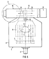
- FIG. 5 shows an axial piston machine in a front view
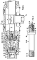
- FIG. 6 shows the known adjusting device in section as a detail of Axial piston machine shows.
- the throughput volume is of the inclined axis type which is generally known, so that a detailed description is not required.
- Only the main components of the axial piston machine 1 shown in FIG. 5 are briefly listed below, namely a housing 2, an input and output shaft 3 (pump / motor) mounted in the housing, and one rotatable in the housing 2 in the sense of the double arrows 4 and 5 as well as pivotably mounted cylinder drum 6 with a plurality of piston bores (not shown) arranged on a pitch circle and essentially axially extending, in which pistons (indicated by center lines) are slidably guided, which are supported on a slideway 7, an adjusting device generally designated 8 with an electric or hydraulic adjustment motor 9 for adjusting an adjustment member 12 which can be adjusted along the double arrow 11 in the form of a slide and which is not shown by a link guide 13 hydraulic control parts as well as with the cylinder drum 6 for the purpose of their adjustment in drive connection, and an adjusting device 15 arranged opposite the adjustment motor 9 for positioning the adjustment member
- the essential parts of the adjusting device 15 shown as detail X in section and enlarged in FIG. 6 are an adjusting threaded bolt 16, which is resiliently fixed along the axis of the adjusting member 12 by a damping device, generally designated 17, and a lock screw, generally designated 18 to secure the threaded bolt 16 against unintentional adjustment.
- the adjusting member is accommodated in a shoulder housing part 19, to which a pot-shaped housing shoulder 21, in which the damping device 17 is accommodated, is fastened on its side facing away from the adjusting motor 9.
- the adjusting member 12 On its side facing away from the adjusting motor 9, the adjusting member 12 is guided longitudinally in a bushing 22, which is simultaneously received in the housing part 19 and in the housing shoulder 21 and centers the latter against one another, the bushing 22 being axially fixed by shoulders 23.
- the damping device 17 has two axially arranged spring cups 24, each with an outer flange 25, a cylindrical section 26 and an inner flange 27, the cylindrical sections 26 projecting from one another from the outer flanges 25 and the inner flanges 27 being arranged at the inner ends of the cylindrical sections 26 .
- the cavities enclosed by the spring cups 24 are designated 28 and 29.
- the outer flanges 25 are clamped in an axially extending compression spring 31, which prestresses the spring cups 24 against shoulders 32, 33, of which the inner shoulder 32 is formed by the bushing 22 and the outer shoulder 33 by an inner flange 34, into which a hat-shaped cover 35 is inserted.
- the spring cups 24 together with the housing projection 21 represent a holder for the threaded bolt 16, which rests on the inside with a collar 36 and on the outside with a clamping nut 37 on the opposite sides of the inner flanges 27 of the spring cups 24 and is thereby positioned axially; the threaded bolt 16 passes through a shaft 38 corresponding holes in the inner flanges 27 with play.
- the threaded bolt 16 has the setting thread 42 as an external thread, with which it is screwed into a central blind hole 43 in the adjusting member 12 with a corresponding setting thread 44 as an internal thread.
- the non-rotatably longitudinal adjustment member 12 can thus be adjusted and thus positioned independently of the adjustment motor 9 from its shown central position to the right and left, namely in the present case in the zero position of the throughput volume setting.
- an engagement member 46 in the form of an Allen recess is provided at its outer end 45, into which a tool, here an Allen key, can be inserted after removing the cover 35.
- the threaded bolt 16 has an axial through-bore 47, the inner end section of which represents a threaded bore 48 in which the countersunk screw 18 is screwed in with an engagement element 49.
- the lock screw is formed with its tip Tension the counter member 51 against the bottom of the blind bore 43, whereby the adjusting member 12 and the threaded bolt 16 are pressed apart for the purpose of locking.
- the threaded bolt 16 is assigned a further adjusting device 52 at its outer end 45, which is formed by the adjusting thread 54 and the clamping nut 37.
- the further adjusting device 52 By means of the further adjusting device 52, the distance between the collar 36 and the clamping nut 37 can be precisely adapted to the existing distance between the sides of the inner flanges 27 of the spring cups 24 facing away from one another.
- the clamping nut 37 designed as an accordion-shaped special nut serves to secure the respective adjustment, ie to prevent unintentional relative rotation between the clamping nut 37 and the threaded bolt 16. It has been shown in practice that in the further adjusting device 52 too There is a risk of unintentional adjustment, in particular if the clamping nut 37 lifts from the associated inner flange 27 during the respective adjustment path of the adjustment member 12.
- the invention has for its object to improve the adjustment or adjustment between the threaded bolt and the adjusting member.
- a threaded part is available as an additional clamping part, which because of its thread engagement with the adjusting member engages the latter over a large area and can be effectively locked by turning the counter screw by means of its thread.
- the threaded section of the threaded bolt consists of two parts which can be braced against one another by means of the central lock screw. This creates an effective fixing device that prevents adjustment of the adjustment.
- the existing setting thread of the adjusting member is used to receive the threaded part.
- the counter screw on the threaded bolt can be supported in various ways.
- the embodiment according to claim 3 is a very simple, practical and inexpensive solution.
- the configuration according to claim 5 further improves the locking by means of the adjusting device, because the threaded part is prevented from rotating with the locking screw. Such a take away would be particularly problematic when the pitch of the internal and external threads of the threaded part match. In addition, this ensures a distance between the threaded bolt and the threaded part that enables the clamping effect.
- an additional threaded part 55 with an external thread and an internal thread is provided as the counter element 51, the external thread corresponding to the adjusting thread 44 of the adjusting element 12 and the internal thread corresponding to the external thread 53 of the counter screw 18 and being received on the latter.
- the counter screw 18 extends through a thread-free axial through-hole 56 in the threaded bolt 16, and it has a screw head 57 with an engagement element (not shown) for a counter tool at its end facing away from the threaded part 55.
- a stop 61 is provided in the form of a pin or clamping sleeve that passes through the counter screw 18 in a transverse hole, as a result of which the threaded part 55 is held captively on the counter screw 18.
- the stop 61 also ensures the constant engagement of a claw coupling 62 which is arranged between the threaded bolt 16 and the threaded part 55 and which prevents rotation of the threaded part 55 and by means of a transverse groove 63 in the end face of the threaded bolt 16 facing the threaded part 55 and one in the transverse groove 63 bordering web 64 is formed on the end face of the threaded part 55 facing the threaded bolt 16.
- an elastic member 65 in the form of an O-ring made of elastic plastic or rubber is arranged, which facilitates the screwing in of the component formed by the threaded bolt 16, the counter screw 18 and the threaded part 55.
- the counter screw 18 To lock the threaded bolt 16 in the adjusting member 12, the counter screw 18 must be turned clockwise in the presence of a right-hand thread, as a result of which the threaded part 55 is braced against the threaded bolt 16. Because of the length 1 of the counter screw 18, which is considerably greater than that of the known design, it has a considerable degree of expansion, which has a favorable effect on the fixing or locking. It is therefore advantageous to use an expansion screw as a counter screw 18.
- the clamping nut is formed from two nut parts 66, 67, which have a distance or gap between them and can be braced against one another by at least one, in the present exemplary embodiment, two diametrically opposite lock screws 69.
- the inner nut part 66 has a threaded hole and the outer nut part 67 has a through hole, preferably with an external depression for the head of the counter screw 69, so that the latter can be operated easily.
- the at least one lock screw 69 also simultaneously leads to an anti-rotation lock between the nut parts 66, 67.
Landscapes
- Engineering & Computer Science (AREA)
- Mechanical Engineering (AREA)
- General Engineering & Computer Science (AREA)
- Fluid-Damping Devices (AREA)
- Transmission Devices (AREA)
Claims (13)
- Dispositif d'ajustement (15) pour ajuster un organe de réglage (12) pour un dispositif de réglage (8) d'une machine (1) à pistons axiaux ou radiaux, à débit volumétrique réglable, dans lequel l'organe de réglage (12) est disposé de manière réglable dans un guidage (22) du côté de la machine et présente un alésage (43) avec un filetage (44) de réglage, dans lequel est vissé un goujon fileté de réglage (16) maintenu en étant immobilisé axialement dans un support (21, 24) du côté de la machine, ce goujon (16) se vissant par sa section d'extrémité intérieure (41) présentant un filetage de réglage (42) et étant bloqué dans sa position d'engagement avec l'organe de réglage (12) par un contre-organe (51) disposé dans l'alésage (43) en étant voisin de la section d'extrémité intérieure (41) du goujon fileté de réglage (16), ce contre-organe (51) étant réglable par rapport au goujon fileté de réglage (16) au moyen d'une contre-vis (18) avec un filetage externe, disposée dans un alésage axial traversant le goujon fileté de réglage (16) et prenant appui axialement sur celui-ci,
caractérisé en ce que le contre-organe (51) est sous la forme d'une pièce filetée cylindrique creuse séparée (55) avec un filetage externe et un filetage interne, au moyen desquels elle se trouve en engagement par vissage avec un filetage interne (44) ménagé dans l'alésage (43) dans l'organe de réglage (12) et avec le filetage externe (53) de la contre-vis (18). - Dispositif d'ajustement selon la revendication 1, caractérisé en ce que le filetage interne (44) se trouvant en engagement avec le filetage externe de la pièce filetée (55), ménagé dans l'alésage (43) de l'organe modificateur de réglage (12) est le filetage de réglage (44) de celui-ci.
- Dispositif d'ajustement selon la revendication 1 ou 2, caractérisé en ce que la contre-vis (18) traverse l'alésage continu (56) dans le goujon fileté de réglage (16) et présente une tête de vis (57) qui coopère avec un épaulement (59) ménagé sur le goujon fileté (16) et opposé à la pièce filetée (55).
- Dispositif d'ajustement selon la revendication 3, caractérisé en ce que l'épaulement (59) et/ou la tête de vis (57) sont disposés dans la zone de l'extrémité extérieure (45) du goujon fileté (16) opposée à la pièce filetée (55).
- Dispositif d'ajustement selon une des revendications 1 à 4, caractérisé en ce qu'un dispositif d'arrêt (62) pour empêcher la pièce filetée (55) de tourner est disposé sur le goujon fileté (16).
- Dispositif d'ajustement selon la revendication 5, caractérisé en ce que le dispositif anti-rotation (62) est constitué par un accouplement à griffes (62).
- Dispositif d'ajustement selon la revendication 6, caractérisé en ce que l'accouplement à griffes (62) est constitué par une rainure transversale (63) et par un tenon (64) s'engageant dans celle-ci, ménagés respectivement sur les côtés tournés l'un vers l'autre du goujon fileté (16) et de la pièce filetée (55).
- Dispositif d'ajustement selon une des revendications 1 à 7, caractérisé en ce que la pièce filetée (55) est protégée contre un dévissage de la contre-vis (18) par une butée (61) sur la contre-vis (18) de préférence sous la forme d'une goupille traversant la contre-vis (18) ou d'une douille de serrage.
- Dispositif d'ajustement selon la revendication 8, caractérisé en ce que l'appui de la pièce filetée (55) sur la butée (61) assure l'engagement de l'accouplement à griffes (62).
- Dispositif d'ajustement selon une des revendications 1 à 9, caractérisé en ce qu'un organe élastique (65) agissant dans le sens axial, de préférence sous la forme d'un joint torique en caoutchouc ou en matière plastique, est disposé entre le goujon fileté (16) et la pièce filetée (55).
- Dispositif d'ajustement selon une des revendications 1 à 10, dans lequel est associé au goujon fileté (16) un dispositif amortisseur (17) bilatéral qui présente deux cuvettes de ressort (24) précontraintes par une force de ressort tendant à les écarter l'une de l'autre contre des épaulements (32, 33) sur lesquels le goujon fileté (16) prend appui, tandis que sur l'extrémité extérieure (45) du goujon fileté (16) est prévu un autre filetage de réglage (54) sur lequel est vissé un écrou (37) pouvant être bloqué par serrage contre une rotation involontaire et prenant appui indirectement ou directement sur la cuvette de ressort (24) extérieure,
caractérisé en ce que l'écrou (37) se compose de deux parties d'écrou (66, 67) espacées axialement l'une de l'autre, pouvant être serrées axialement par au moins une contre-vis (69) disposée sensiblement parallèlement à l'axe. - Dispositif d'ajustement selon la revendication 11, caractérisé en ce que la contre-vis (69) est vissée dans une (66) des parties d'écrou (66, 67) et prend appui en sens périphérique sur l'autre partie d'écrou (67).
- Dispositif d'ajustement selon la revendication 12, caractérisé en ce que la contre-vis (69) traverse la partie d'écrou extérieure (67) dans un trou de passage à partir de l'extérieur et est vissée dans la partie d'écrou intérieure (66).
Applications Claiming Priority (2)
| Application Number | Priority Date | Filing Date | Title |
|---|---|---|---|
| DE3800892A DE3800892A1 (de) | 1988-01-14 | 1988-01-14 | Justiervorrichtung fuer einen einstell-gewindebolzen |
| DE3800892 | 1988-01-14 |
Publications (3)
| Publication Number | Publication Date |
|---|---|
| EP0324112A2 EP0324112A2 (fr) | 1989-07-19 |
| EP0324112A3 EP0324112A3 (en) | 1990-02-21 |
| EP0324112B1 true EP0324112B1 (fr) | 1994-04-06 |
Family
ID=6345273
Family Applications (1)
| Application Number | Title | Priority Date | Filing Date |
|---|---|---|---|
| EP88120649A Expired - Lifetime EP0324112B1 (fr) | 1988-01-14 | 1988-12-09 | Dispositif d'ajustement pour une vis de réglage |
Country Status (2)
| Country | Link |
|---|---|
| EP (1) | EP0324112B1 (fr) |
| DE (2) | DE3800892A1 (fr) |
Families Citing this family (2)
| Publication number | Priority date | Publication date | Assignee | Title |
|---|---|---|---|---|
| FI96149C (fi) * | 1994-05-25 | 1996-05-10 | Seppo Metsaelae | Hienomekaaninen säätölaite |
| DE69734684T2 (de) * | 1997-12-16 | 2006-08-10 | Seppo Metsälä | Feinmechanische querpositionierungsvorrichtung |
Family Cites Families (10)
| Publication number | Priority date | Publication date | Assignee | Title |
|---|---|---|---|---|
| FR2079E (fr) * | 1903-12-26 | Andre Minne | Nouveau système de contre-écrou dit contre-écrou rationnel | |
| DE800512C (de) * | 1948-10-02 | 1950-11-13 | Paul Steinmetzer | Schraubenmutter-Sicherung |
| US2998733A (en) * | 1959-06-02 | 1961-09-05 | Kenneth W Thompson | Control device |
| DE1453657B2 (de) * | 1964-07-17 | 1972-07-06 | Brüninghaus Hydraulik GmbH, 7240 Horb | Verstelleinrichtung, insbesondere fuer axialkolbenmaschinen |
| JPS5694019A (en) * | 1979-12-26 | 1981-07-30 | Masao Kanazawa | Lock bolt |
| US4466261A (en) * | 1980-10-20 | 1984-08-21 | Zimmer John C | Security apparatus |
| DE3413444C2 (de) * | 1984-04-10 | 1986-03-27 | Robert Bosch Gmbh, 7000 Stuttgart | Sicherungs- und Anzeigevorrichtung gegen unbefugtes Verstellen einer Schraube |
| FR2566483B1 (fr) * | 1984-06-21 | 1991-10-04 | Cuilleron J | Ecrou a double effet permettant le reglage et le rattrapage des jeux dans les assemblages mecaniques filetes |
| DE3433738A1 (de) * | 1984-09-14 | 1986-03-20 | Fa. Carl Zeiss, 7920 Heidenheim | Einrichtung zur lagemaessigen fixierung eines gewindebolzens |
| CH666093A5 (de) * | 1985-05-30 | 1988-06-30 | Sulzer Ag | Schraubverbindung. |
-
1988
- 1988-01-14 DE DE3800892A patent/DE3800892A1/de not_active Ceased
- 1988-12-09 DE DE88120649T patent/DE3888956D1/de not_active Expired - Fee Related
- 1988-12-09 EP EP88120649A patent/EP0324112B1/fr not_active Expired - Lifetime
Also Published As
| Publication number | Publication date |
|---|---|
| EP0324112A3 (en) | 1990-02-21 |
| DE3800892A1 (de) | 1989-07-27 |
| DE3888956D1 (de) | 1994-05-11 |
| EP0324112A2 (fr) | 1989-07-19 |
Similar Documents
| Publication | Publication Date | Title |
|---|---|---|
| DE2339873C2 (de) | Anordnung zum Einstellen und Befestigen eines ein Schneidplättchen tragenden Blocks in einer nutförmigen Aufnahme im Werkzeugkörper eines spanabhebenden Werkzeugs | |
| DE3610284C2 (fr) | ||
| EP0039765B1 (fr) | Dispositif pour le montage de plaques flexibles sur un cylindre de plaques pour rotatives | |
| DE102007030876B4 (de) | Werkzeug zur spanabtragenden Bearbeitung von Werkstücken | |
| DE3929802C1 (fr) | ||
| EP0962280B1 (fr) | Dispositif d'alignement | |
| DE68914680T2 (de) | Werkzeughalter mit spannmechanismus mit eingebautem blockierkeil. | |
| DE2141366A1 (de) | Werkzeug zur Montage bzw. Demontage von Schraubenfeder-Stoßdämpfern und Verfahren unter Verwendung dieses Werkzeuges | |
| DE3928876C2 (de) | Einrichtung zum Justieren eines Stoßfängers an einem Kraftfahrzeug | |
| EP0324112B1 (fr) | Dispositif d'ajustement pour une vis de réglage | |
| DE3029133C2 (de) | Werkzeughalter | |
| DE8627319U1 (de) | Segment zum Ausrichten einer Formplatte auf einem Werkzeugmaschinentisch | |
| DE2953815C2 (de) | Gummituchspannvorrichtung | |
| EP0308645B1 (fr) | Vis d'extension pour le redressement des dents | |
| DE2158779A1 (de) | Nachstellbare Maschinenreibahle | |
| EP0598165A1 (fr) | Dispositif pour assembler des pièces de façon tournante, par exemple leviers à lames, entraîneurs de lames et métiers à tisser pourvu d'un tel dispositif | |
| DE4407270C1 (de) | Schneidplatten-Einstellvorrichtung | |
| EP1134440B1 (fr) | Ensemble de connexion | |
| DE19750614C2 (de) | Vorrichtung zum Verändern des Verdrängungsvolumens einer hydrostatischen Maschine | |
| AT387823B (de) | Hilfseinrichtung fuer eine betaetigungsstange der an pumpen-duesenaggregaten von einspritz-brennkraftmaschinen vorgesehenen regelglieder | |
| DE20106561U1 (de) | Vorrichtung zum Verbinden von Profilstäben | |
| EP0255706B1 (fr) | Dispositif de réglage de la position relative d'éléments de construction, en particulier dispositif de tension pour transmission à organe flexible sans fin | |
| DE3009288A1 (de) | Zweikreisdruckregler | |
| EP2562460B1 (fr) | Setting device | |
| DE102016210430A1 (de) | Stoßwerkzeug für Innenkonturen, eine Schneidplatte und einen Schneidplattenhalter |
Legal Events
| Date | Code | Title | Description |
|---|---|---|---|
| PUAI | Public reference made under article 153(3) epc to a published international application that has entered the european phase |
Free format text: ORIGINAL CODE: 0009012 |
|
| AK | Designated contracting states |
Kind code of ref document: A2 Designated state(s): DE GB IT SE |
|
| PUAL | Search report despatched |
Free format text: ORIGINAL CODE: 0009013 |
|
| AK | Designated contracting states |
Kind code of ref document: A3 Designated state(s): DE GB IT SE |
|
| 17P | Request for examination filed |
Effective date: 19900307 |
|
| 17Q | First examination report despatched |
Effective date: 19920909 |
|
| GRAA | (expected) grant |
Free format text: ORIGINAL CODE: 0009210 |
|
| AK | Designated contracting states |
Kind code of ref document: B1 Designated state(s): DE GB IT SE |
|
| REF | Corresponds to: |
Ref document number: 3888956 Country of ref document: DE Date of ref document: 19940511 |
|
| ITF | It: translation for a ep patent filed | ||
| GBT | Gb: translation of ep patent filed (gb section 77(6)(a)/1977) |
Effective date: 19940712 |
|
| EAL | Se: european patent in force in sweden |
Ref document number: 88120649.4 |
|
| PLBE | No opposition filed within time limit |
Free format text: ORIGINAL CODE: 0009261 |
|
| STAA | Information on the status of an ep patent application or granted ep patent |
Free format text: STATUS: NO OPPOSITION FILED WITHIN TIME LIMIT |
|
| 26N | No opposition filed | ||
| REG | Reference to a national code |
Ref country code: GB Ref legal event code: IF02 |
|
| PGFP | Annual fee paid to national office [announced via postgrant information from national office to epo] |
Ref country code: SE Payment date: 20061213 Year of fee payment: 19 |
|
| PGFP | Annual fee paid to national office [announced via postgrant information from national office to epo] |
Ref country code: DE Payment date: 20061218 Year of fee payment: 19 |
|
| PGFP | Annual fee paid to national office [announced via postgrant information from national office to epo] |
Ref country code: GB Payment date: 20061221 Year of fee payment: 19 |
|
| PGFP | Annual fee paid to national office [announced via postgrant information from national office to epo] |
Ref country code: IT Payment date: 20061231 Year of fee payment: 19 |
|
| EUG | Se: european patent has lapsed | ||
| GBPC | Gb: european patent ceased through non-payment of renewal fee |
Effective date: 20071209 |
|
| PG25 | Lapsed in a contracting state [announced via postgrant information from national office to epo] |
Ref country code: DE Free format text: LAPSE BECAUSE OF NON-PAYMENT OF DUE FEES Effective date: 20080701 Ref country code: SE Free format text: LAPSE BECAUSE OF NON-PAYMENT OF DUE FEES Effective date: 20071210 |
|
| PG25 | Lapsed in a contracting state [announced via postgrant information from national office to epo] |
Ref country code: GB Free format text: LAPSE BECAUSE OF NON-PAYMENT OF DUE FEES Effective date: 20071209 |
|
| PG25 | Lapsed in a contracting state [announced via postgrant information from national office to epo] |
Ref country code: IT Free format text: LAPSE BECAUSE OF NON-PAYMENT OF DUE FEES Effective date: 20071209 |