EP0323718B1 - Unité de palier linéaire et guidages rectilignes utilisant de telles unités - Google Patents
Unité de palier linéaire et guidages rectilignes utilisant de telles unités Download PDFInfo
- Publication number
- EP0323718B1 EP0323718B1 EP88311710A EP88311710A EP0323718B1 EP 0323718 B1 EP0323718 B1 EP 0323718B1 EP 88311710 A EP88311710 A EP 88311710A EP 88311710 A EP88311710 A EP 88311710A EP 0323718 B1 EP0323718 B1 EP 0323718B1
- Authority
- EP
- European Patent Office
- Prior art keywords
- retainer
- ball
- unit
- self
- bearing
- Prior art date
- Legal status (The legal status is an assumption and is not a legal conclusion. Google has not performed a legal analysis and makes no representation as to the accuracy of the status listed.)
- Expired - Lifetime
Links
Images


Classifications
-
- F—MECHANICAL ENGINEERING; LIGHTING; HEATING; WEAPONS; BLASTING
- F16—ENGINEERING ELEMENTS AND UNITS; GENERAL MEASURES FOR PRODUCING AND MAINTAINING EFFECTIVE FUNCTIONING OF MACHINES OR INSTALLATIONS; THERMAL INSULATION IN GENERAL
- F16C—SHAFTS; FLEXIBLE SHAFTS; ELEMENTS OR CRANKSHAFT MECHANISMS; ROTARY BODIES OTHER THAN GEARING ELEMENTS; BEARINGS
- F16C29/00—Bearings for parts moving only linearly
- F16C29/04—Ball or roller bearings
- F16C29/06—Ball or roller bearings in which the rolling bodies circulate partly without carrying load
- F16C29/0614—Ball or roller bearings in which the rolling bodies circulate partly without carrying load with a shoe type bearing body, e.g. a body facing one side of the guide rail or track only
- F16C29/0616—Ball or roller bearings in which the rolling bodies circulate partly without carrying load with a shoe type bearing body, e.g. a body facing one side of the guide rail or track only for supporting load essentially in a single direction
-
- F—MECHANICAL ENGINEERING; LIGHTING; HEATING; WEAPONS; BLASTING
- F16—ENGINEERING ELEMENTS AND UNITS; GENERAL MEASURES FOR PRODUCING AND MAINTAINING EFFECTIVE FUNCTIONING OF MACHINES OR INSTALLATIONS; THERMAL INSULATION IN GENERAL
- F16C—SHAFTS; FLEXIBLE SHAFTS; ELEMENTS OR CRANKSHAFT MECHANISMS; ROTARY BODIES OTHER THAN GEARING ELEMENTS; BEARINGS
- F16C29/00—Bearings for parts moving only linearly
- F16C29/04—Ball or roller bearings
- F16C29/06—Ball or roller bearings in which the rolling bodies circulate partly without carrying load
- F16C29/0676—Ball or roller bearings in which the rolling bodies circulate partly without carrying load with a bearing body or carriage almost fully embracing the guide rail or track, e.g. a circular sleeve with a longitudinal slot for the support posts of the rail
-
- F—MECHANICAL ENGINEERING; LIGHTING; HEATING; WEAPONS; BLASTING
- F16—ENGINEERING ELEMENTS AND UNITS; GENERAL MEASURES FOR PRODUCING AND MAINTAINING EFFECTIVE FUNCTIONING OF MACHINES OR INSTALLATIONS; THERMAL INSULATION IN GENERAL
- F16C—SHAFTS; FLEXIBLE SHAFTS; ELEMENTS OR CRANKSHAFT MECHANISMS; ROTARY BODIES OTHER THAN GEARING ELEMENTS; BEARINGS
- F16C29/00—Bearings for parts moving only linearly
- F16C29/04—Ball or roller bearings
- F16C29/06—Ball or roller bearings in which the rolling bodies circulate partly without carrying load
- F16C29/068—Ball or roller bearings in which the rolling bodies circulate partly without carrying load with the bearing body fully encircling the guide rail or track
- F16C29/0683—Ball or roller bearings in which the rolling bodies circulate partly without carrying load with the bearing body fully encircling the guide rail or track the bearing body encircles a rail or rod of circular cross-section, i.e. the linear bearing is not suited to transmit torque
- F16C29/0685—Ball or roller bearings in which the rolling bodies circulate partly without carrying load with the bearing body fully encircling the guide rail or track the bearing body encircles a rail or rod of circular cross-section, i.e. the linear bearing is not suited to transmit torque with balls
- F16C29/069—Ball or roller bearings in which the rolling bodies circulate partly without carrying load with the bearing body fully encircling the guide rail or track the bearing body encircles a rail or rod of circular cross-section, i.e. the linear bearing is not suited to transmit torque with balls whereby discrete load bearing elements, e.g. discrete load bearing plates or discrete rods, are provided in a retainer and form the load bearing tracks
-
- F—MECHANICAL ENGINEERING; LIGHTING; HEATING; WEAPONS; BLASTING
- F16—ENGINEERING ELEMENTS AND UNITS; GENERAL MEASURES FOR PRODUCING AND MAINTAINING EFFECTIVE FUNCTIONING OF MACHINES OR INSTALLATIONS; THERMAL INSULATION IN GENERAL
- F16C—SHAFTS; FLEXIBLE SHAFTS; ELEMENTS OR CRANKSHAFT MECHANISMS; ROTARY BODIES OTHER THAN GEARING ELEMENTS; BEARINGS
- F16C29/00—Bearings for parts moving only linearly
- F16C29/04—Ball or roller bearings
- F16C29/06—Ball or roller bearings in which the rolling bodies circulate partly without carrying load
- F16C29/068—Ball or roller bearings in which the rolling bodies circulate partly without carrying load with the bearing body fully encircling the guide rail or track
- F16C29/0692—Ball or roller bearings in which the rolling bodies circulate partly without carrying load with the bearing body fully encircling the guide rail or track the bearing body encircles a guide rail or track of non-circular cross-section, e.g. with grooves or protrusions, i.e. the linear bearing is suited to transmit torque
- F16C29/0695—Ball or roller bearings in which the rolling bodies circulate partly without carrying load with the bearing body fully encircling the guide rail or track the bearing body encircles a guide rail or track of non-circular cross-section, e.g. with grooves or protrusions, i.e. the linear bearing is suited to transmit torque with balls
- F16C29/0697—Ball or roller bearings in which the rolling bodies circulate partly without carrying load with the bearing body fully encircling the guide rail or track the bearing body encircles a guide rail or track of non-circular cross-section, e.g. with grooves or protrusions, i.e. the linear bearing is suited to transmit torque with balls with polygonal guide rail or track
Landscapes
- Engineering & Computer Science (AREA)
- General Engineering & Computer Science (AREA)
- Mechanical Engineering (AREA)
- Bearings For Parts Moving Linearly (AREA)
- Knitting Machines (AREA)
- Turning (AREA)
- Electrical Discharge Machining, Electrochemical Machining, And Combined Machining (AREA)
Claims (17)
- Unité de palier linéaire (20) individuelle entièrement autonome, adaptée pour constituer une ligne unique de support palier pour un élément (40) animé d'un mouvement glissant relatif à cela, cette unité (20) pouvant être positionée adjacente à des unités (20) analogues supplémentaires pour constituer de la sorte des lignes supplémentaires de support palier pour ledit élément, ladite unité (20) comportant les composants d'assemblage constitués par :
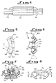
un dispositif de retenue (22) allongé expansible latéralement présentant des faces de retenue (31, 34) opposées dont l'une (34) fait face audit élément (40), ledit dispositif de retenue (22) ayant une partie de corps central (32) et des sections d'extrémité opposées (26), ledit dispositif de retenue (22) comprenant un chemin de roulement sans fin incluant des voies de virage (44) pour billes disposées dans les sections d'extrémité respectives (26) et des voies de roulement (36, 42) chargées de billes et non chargées de billes dirigées longitudinalement en ligne droite, s'étendant entre des extrémités correspondantes des voies de virage, la voie chargée de billes (36) comportant une ouverture (38) sur une face (34) dudit dispositif de retenue (22), la voie non chargée de billes (42) étant définie par une encoche ouverte sur l'autre face (31) dudit dispositif de retenue (22),
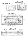
une pluralité de billes (28) logées dans ledit chemin de roulement et pouvant déplacer autour dudit chemin de roulement sans fin, sensibles au déplacement relatif glissant dudit élément (40) en contact support avec les billes (28) dans la voie chargée de billes (36), et une plaque palier allongée (30), ledit dispositif de retenue (22) comportant un moyen de définition d'un logement (50) réceptif à la plaque palier disposé le long de la voie chargée de billes (36) et où les billes (28) de la voie chargée de billes (36) peuvent engager la plaque palier (30) éloignée du contact support desdites billes (28) avec ledit élément (40) pour transmettre de la sorte la charge de palier des billes (28) à ladite plaque palier (30),
caractérisée en ce que :
ladite plaque palier (30) prolonge au-delà des extrémités de ladite partie (32) du corps central du dispositif de retenue, une distance à l'intérieur des sections d'extrémité (26) du dispositif de retenue,
des moyens de couvercle (24) non amovibles montés sur chacune des sections d'extrémité (26) dudit dispositif de retenue (22) pour maintenir captives les billes (28) dans les voies de virage des billes (14) lorsqu'elles passent en se déplaçant depuis la voie chargée de billes à la voie non chargée de billes (36, 42) et pour maintenir captive ladite plaque palier (30) dans ledit logement (50), la partie (32) du corps central de retenue comportant un rebord de captage (62a) s'étendant le long d'une marge de ladite voie non chargée de billes (42) définissant une encoche pour maintenir les billes (28) captives lorsqu'elles se déplacent le long de ladite voie non chargée de billes (42), le dispositif de retenue (22) et lesdites structures de moyens de couvercle (24) comportant des périphéries extérieures transversales qui décrivent des trajectoires enveloppes identiques. - Unité de palier linéaire autonome selon la revendication 1, dans laquelle ledit moyen de définition du logement de retenue (50) comporte une paire de membrures (48) s'étendant verticalement à partir du dispositif de retenue (22) et adjacentes aux marges de ladite voie chargée de billes (36).
- Unité de palier linéaire autonome selon la revendication 2, dans laquelle les parties inférieures des parois intérieures se faisant face desdites membrures (48) sont en continuité avec des épaulements latéraux (50) sur lesquels repose ladite plaque palier (30), celle-ci ayant, sur au moins une partie importante de sa longeur, une épaisseur égale ou légèrement supérieure à celle de l'extension verticale desdites membrures (48).
- Unité de palier linéaire autonome selon la revendication 3, dans laquelle les membrures (48) sont de même étendue l'une par rapport à l'autre, leurs extrémités se prolongeant au-delà des extrémités de la parties de corps central (32) du dispositif de retenue à l'intérieur des sections d'extrémité (26) du dispositif de retenue.
- Unité de palier linéaire autonome selon la revendication 4, dans laquelle les sections d'extrémité. (26) dudit dispositif de retenue (22) sont de dimensions plus réduites par rapport à la partie du corps central (22) et où au moins les parties d'extrémité desdites membrures (48) et de ladite plage palier (30), là où celles-ci s'étendent à l'intérieur desdites sections d'extrémité (26) du dispositif de retenue, sont décalées vers le bas pour ménager un espace destiné à y loger les moyens de couvercle (24) sur les sections d'extrémité (26) du dispositif de retenue et en butée avec sa partie de corps central (32).
- Unité de palier linéaire autonome selon la revendication 5, dans laquelle la surface de la plaque support (30) qui est en contact avec les billes (28) dans la voie chargée de billes (36) comporte une encoche ménagée sur sa longueur.
- Unité de palier linéaire autonome selon la revendication 6, dans laquelle l'encoche (33) de la plaque support a une section incurvée, l'arc décrit par celle-ci ayant un rayon de courbure légèrement supérieur au rayon des billes (28).
- Unité de palier linéaire autonome selon la revendication 5, dans laquelle les sections d'extrémité (26) du dispositif de retenue, sur l'autre face dudit dispositif de retenue, comportent au moins deux surfaces planes en intersection (64, 66), les moyens de couvercle (24) comprenant au moins une surface plane intérieure (84) associée à l'une desdites deux surfaces en intersection (64) pour se mettre en butée avec celle-ci.
- Unité de palier linéaire autonome selon la revendication 1, dans laquelle la voie chargée de billes (36) s'étend longitudinalement et au centre dudit dispositif de retenue (20), la voie non chargée de billes (42) étant espacée de celle-ci latéralement et étant adjacente à la marge longitudinale dudit dispositif de retenue.
- Unité de palier linéaire autonome (22a) selon la revendication 1, en combinaison avec au moins une unité analogue (22b) supplémentaire disposée longitudinalement adjacente à la première unité et ayant une surface marginale latérale pouvant se mettre en butée et en position conforme avec une surface marginale latérale de la première unité, entoure lorsqu'elle est ainsi en butée et encercle partiellement l'élément (18) pour être animé d'un mouvement glissant relatif avec ce dernier, constituant ainsi une ligne supplémentaire de support palier pour l'élément (18).
- Combinaison d'unités de paliers linéaires selon la revendication 10, dans laquelle la surface marginale latérale de l'unité comporte au moins deux parties de surface d'orientation différente, l'une d'entre elles (92) étant en butée contre une partie de surface analogue (92) d'une unité adjacente, l'autre partie de surface comportant une patte de connexion (90) qui lui est solidaire et qui est aussi solidaire de l'autre partie de surface de l'unité adjacente.
- Unité de palier linéaire autonome selon la revendication 1, dans laquelle le dispositif de retenue (22) et les structures de moyen de couvercle (24) ont des périphéries extérieures transversales qui décrivent des trajectoires d'enveloppe identiques, ces périphéries ainsi circonscrites comportant des surfaces supérieure et inférieure qui sont des arcs d'un cercle générés à partir d'un centre commun et des surfaces latérales s'étendant entre les extrémités desdites surfaces supérieure et inférieure, lesdites surfaces latérales comportant chacune une partie droite inférieure (58) qui diverge par rapport à l'autre et une partie droite supérieure (56) qui est inclinée par rapport à la partie inférieure dans la direction de l'autre surface latérale.
- Unité de palier linéaire autonome selon la revendication 12, dans laquelle la partie droite supérieure (56) des surfaces latérales sont parallèles entre elles.
- Unité de palier linéaire autonome selon la revendication 1, dans laquelle le dispositif de retenue (22) et les structures de moyens de couvercle (24) ont des périphéries extérieures transversales qui décrivent des trajectoires à enveloppe identique, de telles périphéries circonscrites comportant des surfaces supérieure et inférieure uniformément espacées l'une par rapport à l'autre et des surfaces latérales s'étendant entre les extrémités desdites surfaces supérieure et inférieure comportant au moins deux parties, l'une des parties étant inclinée par rapport à l'autre.
- Unité de palier linéaire autonome selon la revendication 14, dans laquelle lesdites surfaces supérieure et inférieure sont des surfaces à lignes droites parallèles.
- Unité de palier linéaire autonome selon la revendication 1, dans laquelle le dispositif de retenue (22) et les moyens de couvercle (24) sont des composants en un matériau thermoplastique moulé.
- Unité de palier linéaire autonome (22a) selon la revendication 16 qui, en combinaison avec une pluralité de telles unités supplémentaires (22b, 22c, 22d), constitue une chaîne d'unités, chaque unité de la chaîne étant connectée à une unité adjacente par des pattes de connexion (90) solidaires des côtés des parties (32) du corps central du dispositif de retenue de chacune de ces unités et des parties (32) du corps central des unités adjacentes.
Priority Applications (1)
| Application Number | Priority Date | Filing Date | Title |
|---|---|---|---|
| AT88311710T ATE95284T1 (de) | 1987-12-10 | 1988-12-09 | Lagereinheit fuer laengsbewegungen und linearfuehrungen. |
Applications Claiming Priority (2)
| Application Number | Priority Date | Filing Date | Title |
|---|---|---|---|
| US132065 | 1987-12-10 | ||
| US07/132,065 US4815862A (en) | 1987-12-10 | 1987-12-10 | Self-contained linear bearing unit and linear bearings embodying such units |
Publications (3)
| Publication Number | Publication Date |
|---|---|
| EP0323718A2 EP0323718A2 (fr) | 1989-07-12 |
| EP0323718A3 EP0323718A3 (en) | 1990-02-07 |
| EP0323718B1 true EP0323718B1 (fr) | 1993-09-29 |
Family
ID=22452294
Family Applications (1)
| Application Number | Title | Priority Date | Filing Date |
|---|---|---|---|
| EP88311710A Expired - Lifetime EP0323718B1 (fr) | 1987-12-10 | 1988-12-09 | Unité de palier linéaire et guidages rectilignes utilisant de telles unités |
Country Status (4)
| Country | Link |
|---|---|
| US (1) | US4815862A (fr) |
| EP (1) | EP0323718B1 (fr) |
| AT (1) | ATE95284T1 (fr) |
| DE (1) | DE3884594T2 (fr) |
Families Citing this family (20)
| Publication number | Priority date | Publication date | Assignee | Title |
|---|---|---|---|---|
| DE3911500A1 (de) * | 1989-04-08 | 1990-10-11 | Werner Jacob | Kugelumlaufbuechse fuer eine linearkugelfuehrung |
| US5407249A (en) * | 1990-10-15 | 1995-04-18 | Bonutti; Peter M. | Armrest assembly |
| JP2872839B2 (ja) * | 1991-09-02 | 1999-03-24 | 日本トムソン株式会社 | 小形直動転がり案内ユニット |
| US5161897A (en) * | 1991-06-20 | 1992-11-10 | Thomson Industries, Inc. | Linear motion roller bearing assembly |
| US6022079A (en) * | 1991-09-05 | 2000-02-08 | Industrial Ergonomics | Ergonomic arm support |
| US5851054A (en) * | 1991-09-05 | 1998-12-22 | Industrial Ergonomics, Inc. | Ergonomic arm support |
| US5597207A (en) * | 1991-09-05 | 1997-01-28 | Industrial Ergonomics | Ergonomic arm support |
| US5281001A (en) * | 1991-09-05 | 1994-01-25 | Bergsten Jeffrey D | Ergonomic arm support |
| US5369805A (en) * | 1991-09-05 | 1994-12-06 | Bergsten; Jeffrey D. | Ergonomic arm support |
| US6203109B1 (en) | 1991-09-05 | 2001-03-20 | Industrial Ergonomics, Inc. | Ergonomic arm support |
| US5884974A (en) * | 1991-09-05 | 1999-03-23 | Industrial Ergonomics | Ergonomic arm support and bracket |
| DE4318427C2 (de) * | 1993-06-03 | 2001-05-31 | Schaeffler Waelzlager Ohg | Wälzkörperumlauflager |
| US5558442A (en) * | 1993-07-20 | 1996-09-24 | Thomson Industries, Inc. | Linear motion bearing assembly |
| US5346313A (en) * | 1993-07-20 | 1994-09-13 | Thomson Industries, Inc. | Linear motion bearing assembly |
| US5613780A (en) * | 1995-06-29 | 1997-03-25 | Thomson Industries, Inc. | Linear motion bearing assembly |
| DE19937278A1 (de) * | 1999-08-06 | 2001-02-08 | Schaeffler Waelzlager Ohg | Linearwälzlager |
| DE10051770A1 (de) | 2000-10-19 | 2002-05-02 | Ina Schaeffler Kg | Linearwälzlager |
| CN101213383B (zh) * | 2005-06-30 | 2010-04-14 | Thk株式会社 | 滚动引导装置及其制作方法 |
| US10638849B2 (en) | 2016-10-28 | 2020-05-05 | Steelcase Inc. | Convertible body support structure |
| US10423146B2 (en) * | 2018-01-25 | 2019-09-24 | Schaeffler Technologies AG & Co. KG | Carriage with two-piece housing |
Citations (6)
| Publication number | Priority date | Publication date | Assignee | Title |
|---|---|---|---|---|
| US3751121A (en) * | 1971-09-17 | 1973-08-07 | Barden Corp | Segmental cage for linear and linear/rotary bearings |
| US3767276A (en) * | 1971-10-18 | 1973-10-23 | Hein Universal Corp | Ball bearing assembly |
| US3951473A (en) * | 1974-06-01 | 1976-04-20 | Skf Industrial Trading And Development Company, B.V. | Ball bearing for longitudinal movements |
| US4025128A (en) * | 1975-11-12 | 1977-05-24 | Ted Geffner | Antifriction bearings |
| US4456312A (en) * | 1982-09-27 | 1984-06-26 | Thomson Industries, Inc. | Combination of rotary and rectilinear bearing |
| US4572591A (en) * | 1983-09-02 | 1986-02-25 | Skf Kugellagerfabriken Gmbh | Ball bearing arrangement for longitudinal movement on a shaft or the like |
Family Cites Families (10)
| Publication number | Priority date | Publication date | Assignee | Title |
|---|---|---|---|---|
| US2628135A (en) * | 1949-03-15 | 1953-02-10 | Thomson John B | Antifriction bearing for linear motion |
| US2681836A (en) * | 1950-03-09 | 1954-06-22 | Jarund Harry Sigurd Valdemar | Block bearing |
| FR1558579A (fr) * | 1968-01-16 | 1969-02-28 | ||
| DE2003535A1 (de) * | 1970-01-27 | 1971-08-12 | Star Kugelhalter Gmbh Dt | Kugelfuehrung mit einem Kunststoffring |
| DE2626399A1 (de) * | 1976-06-12 | 1977-12-22 | Schaeffler Ohg Industriewerk | Kugellager zur laengsbeweglichen lagerung von wellen |
| DE2725355C2 (de) * | 1977-06-04 | 1984-04-12 | Skf Kugellagerfabriken Gmbh, 8720 Schweinfurt | Kugelbüchse |
| JPS5848775B2 (ja) * | 1981-08-06 | 1983-10-31 | 博 寺町 | 無限摺動用ボ−ルスプライン軸受 |
| US4512617A (en) * | 1984-03-06 | 1985-04-23 | The Barden Corporation | Linear ball bearing which accommodates shaft misalignment |
| US4557530A (en) * | 1984-05-24 | 1985-12-10 | Haase Harold A | Flat, compact, linear ball bearing with wedge-locked eccentric adjustment and removable races in cylindrical seats |
| DE3422444A1 (de) * | 1984-06-16 | 1985-12-19 | Skf Gmbh | Teleskopeinheit |
-
1987
- 1987-12-10 US US07/132,065 patent/US4815862A/en not_active Expired - Lifetime
-
1988
- 1988-12-09 AT AT88311710T patent/ATE95284T1/de not_active IP Right Cessation
- 1988-12-09 DE DE88311710T patent/DE3884594T2/de not_active Expired - Fee Related
- 1988-12-09 EP EP88311710A patent/EP0323718B1/fr not_active Expired - Lifetime
Patent Citations (6)
| Publication number | Priority date | Publication date | Assignee | Title |
|---|---|---|---|---|
| US3751121A (en) * | 1971-09-17 | 1973-08-07 | Barden Corp | Segmental cage for linear and linear/rotary bearings |
| US3767276A (en) * | 1971-10-18 | 1973-10-23 | Hein Universal Corp | Ball bearing assembly |
| US3951473A (en) * | 1974-06-01 | 1976-04-20 | Skf Industrial Trading And Development Company, B.V. | Ball bearing for longitudinal movements |
| US4025128A (en) * | 1975-11-12 | 1977-05-24 | Ted Geffner | Antifriction bearings |
| US4456312A (en) * | 1982-09-27 | 1984-06-26 | Thomson Industries, Inc. | Combination of rotary and rectilinear bearing |
| US4572591A (en) * | 1983-09-02 | 1986-02-25 | Skf Kugellagerfabriken Gmbh | Ball bearing arrangement for longitudinal movement on a shaft or the like |
Also Published As
| Publication number | Publication date |
|---|---|
| DE3884594D1 (de) | 1993-11-04 |
| US4815862A (en) | 1989-03-28 |
| EP0323718A3 (en) | 1990-02-07 |
| ATE95284T1 (de) | 1993-10-15 |
| EP0323718A2 (fr) | 1989-07-12 |
| DE3884594T2 (de) | 1994-05-11 |
Similar Documents
| Publication | Publication Date | Title |
|---|---|---|
| EP0323718B1 (fr) | Unité de palier linéaire et guidages rectilignes utilisant de telles unités | |
| EP1328734B1 (fr) | Segment de palier a mouvement lineaire | |
| US4406502A (en) | Unlimited sliding ball bearing spline assembly | |
| JPS6330820Y2 (fr) | ||
| EP0449595B1 (fr) | Palier linéaire | |
| JPS6343607B2 (fr) | ||
| JPS5861329A (ja) | 再潤滑可能な複列軸受 | |
| JPS6347930B2 (fr) | ||
| KR20100084154A (ko) | 레이디얼 롤링 베어링 특히 2 열 앵귤러 콘택트 볼 베어링 | |
| JPH10220470A (ja) | ボールスプライン | |
| EP0104308A2 (fr) | Palier combiné rotatif et linéaire | |
| US4655611A (en) | Ball spline bearing assembly | |
| US3966284A (en) | Snappable open separators for the cage of rolling thrust bearing elements | |
| US5092685A (en) | Sealing structure for linear motion bearing | |
| JPH0366531B2 (fr) | ||
| JPS62110025A (ja) | 分割構造の軌道輪を有する転がり軸受 | |
| US5221145A (en) | Linear bearing | |
| JPS5936134B2 (ja) | 縦方向玉案内用の玉入りブツシユ | |
| JP2533751Y2 (ja) | 球充填凹所を備える直動球軸受 | |
| KR20010042054A (ko) | 볼 베어링용 케이지와, 이러한 케이지를 구비하는 볼 베어링 | |
| US4438985A (en) | Ball bushing of simplified construction | |
| US5174538A (en) | Rotary support device | |
| JPH11280769A (ja) | ころ軸受 | |
| GB2049070A (en) | Bearings | |
| EP0339630B1 (fr) | Dispositif de support rotatif et procédé de production de ce dispositif |
Legal Events
| Date | Code | Title | Description |
|---|---|---|---|
| PUAI | Public reference made under article 153(3) epc to a published international application that has entered the european phase |
Free format text: ORIGINAL CODE: 0009012 |
|
| AK | Designated contracting states |
Kind code of ref document: A2 Designated state(s): AT DE FR GB IT |
|
| PUAL | Search report despatched |
Free format text: ORIGINAL CODE: 0009013 |
|
| AK | Designated contracting states |
Kind code of ref document: A3 Designated state(s): AT DE FR GB IT |
|
| 17P | Request for examination filed |
Effective date: 19900720 |
|
| 17Q | First examination report despatched |
Effective date: 19911128 |
|
| GRAA | (expected) grant |
Free format text: ORIGINAL CODE: 0009210 |
|
| AK | Designated contracting states |
Kind code of ref document: B1 Designated state(s): AT DE FR GB IT |
|
| PG25 | Lapsed in a contracting state [announced via postgrant information from national office to epo] |
Ref country code: AT Effective date: 19930929 |
|
| REF | Corresponds to: |
Ref document number: 95284 Country of ref document: AT Date of ref document: 19931015 Kind code of ref document: T |
|
| REF | Corresponds to: |
Ref document number: 3884594 Country of ref document: DE Date of ref document: 19931104 |
|
| ITF | It: translation for a ep patent filed |
Owner name: STUDIO TORTA SOCIETA' SEMPLICE |
|
| ET | Fr: translation filed | ||
| PLBE | No opposition filed within time limit |
Free format text: ORIGINAL CODE: 0009261 |
|
| STAA | Information on the status of an ep patent application or granted ep patent |
Free format text: STATUS: NO OPPOSITION FILED WITHIN TIME LIMIT |
|
| 26N | No opposition filed | ||
| PGFP | Annual fee paid to national office [announced via postgrant information from national office to epo] |
Ref country code: GB Payment date: 19991208 Year of fee payment: 12 Ref country code: FR Payment date: 19991208 Year of fee payment: 12 |
|
| PGFP | Annual fee paid to national office [announced via postgrant information from national office to epo] |
Ref country code: DE Payment date: 19991210 Year of fee payment: 12 |
|
| PG25 | Lapsed in a contracting state [announced via postgrant information from national office to epo] |
Ref country code: GB Free format text: LAPSE BECAUSE OF NON-PAYMENT OF DUE FEES Effective date: 20001209 |
|
| GBPC | Gb: european patent ceased through non-payment of renewal fee |
Effective date: 20001209 |
|
| PG25 | Lapsed in a contracting state [announced via postgrant information from national office to epo] |
Ref country code: FR Free format text: LAPSE BECAUSE OF NON-PAYMENT OF DUE FEES Effective date: 20010831 |
|
| REG | Reference to a national code |
Ref country code: FR Ref legal event code: ST |
|
| PG25 | Lapsed in a contracting state [announced via postgrant information from national office to epo] |
Ref country code: DE Free format text: LAPSE BECAUSE OF NON-PAYMENT OF DUE FEES Effective date: 20011002 |
|
| PG25 | Lapsed in a contracting state [announced via postgrant information from national office to epo] |
Ref country code: IT Free format text: LAPSE BECAUSE OF NON-PAYMENT OF DUE FEES;WARNING: LAPSES OF ITALIAN PATENTS WITH EFFECTIVE DATE BEFORE 2007 MAY HAVE OCCURRED AT ANY TIME BEFORE 2007. THE CORRECT EFFECTIVE DATE MAY BE DIFFERENT FROM THE ONE RECORDED. Effective date: 20051209 |