EP0322111B1 - Ereignisfolgenbedingtes Kupplung-zu-Kupplung-Herunterschalten für ein elektronisch gesteuertes automatisches Getriebe - Google Patents
Ereignisfolgenbedingtes Kupplung-zu-Kupplung-Herunterschalten für ein elektronisch gesteuertes automatisches Getriebe Download PDFInfo
- Publication number
- EP0322111B1 EP0322111B1 EP88311070A EP88311070A EP0322111B1 EP 0322111 B1 EP0322111 B1 EP 0322111B1 EP 88311070 A EP88311070 A EP 88311070A EP 88311070 A EP88311070 A EP 88311070A EP 0322111 B1 EP0322111 B1 EP 0322111B1
- Authority
- EP
- European Patent Office
- Prior art keywords
- clutch
- torque
- engagement
- speed ratio
- shift
- Prior art date
- Legal status (The legal status is an assumption and is not a legal conclusion. Google has not performed a legal analysis and makes no representation as to the accuracy of the status listed.)
- Expired - Lifetime
Links
Images


Classifications
-
- F—MECHANICAL ENGINEERING; LIGHTING; HEATING; WEAPONS; BLASTING
- F16—ENGINEERING ELEMENTS AND UNITS; GENERAL MEASURES FOR PRODUCING AND MAINTAINING EFFECTIVE FUNCTIONING OF MACHINES OR INSTALLATIONS; THERMAL INSULATION IN GENERAL
- F16H—GEARING
- F16H61/00—Control functions within control units of change-speed- or reversing-gearings for conveying rotary motion ; Control of exclusively fluid gearing, friction gearing, gearings with endless flexible members or other particular types of gearing
- F16H61/04—Smoothing ratio shift
- F16H61/06—Smoothing ratio shift by controlling rate of change of fluid pressure
- F16H61/061—Smoothing ratio shift by controlling rate of change of fluid pressure using electric control means
-
- F—MECHANICAL ENGINEERING; LIGHTING; HEATING; WEAPONS; BLASTING
- F16—ENGINEERING ELEMENTS AND UNITS; GENERAL MEASURES FOR PRODUCING AND MAINTAINING EFFECTIVE FUNCTIONING OF MACHINES OR INSTALLATIONS; THERMAL INSULATION IN GENERAL
- F16H—GEARING
- F16H59/00—Control inputs to control units of change-speed-, or reversing-gearings for conveying rotary motion
- F16H59/36—Inputs being a function of speed
- F16H59/38—Inputs being a function of speed of gearing elements
- F16H2059/385—Turbine speed
-
- F—MECHANICAL ENGINEERING; LIGHTING; HEATING; WEAPONS; BLASTING
- F16—ENGINEERING ELEMENTS AND UNITS; GENERAL MEASURES FOR PRODUCING AND MAINTAINING EFFECTIVE FUNCTIONING OF MACHINES OR INSTALLATIONS; THERMAL INSULATION IN GENERAL
- F16H—GEARING
- F16H61/00—Control functions within control units of change-speed- or reversing-gearings for conveying rotary motion ; Control of exclusively fluid gearing, friction gearing, gearings with endless flexible members or other particular types of gearing
- F16H61/02—Control functions within control units of change-speed- or reversing-gearings for conveying rotary motion ; Control of exclusively fluid gearing, friction gearing, gearings with endless flexible members or other particular types of gearing characterised by the signals used
- F16H61/0202—Control functions within control units of change-speed- or reversing-gearings for conveying rotary motion ; Control of exclusively fluid gearing, friction gearing, gearings with endless flexible members or other particular types of gearing characterised by the signals used the signals being electric
- F16H61/0204—Control functions within control units of change-speed- or reversing-gearings for conveying rotary motion ; Control of exclusively fluid gearing, friction gearing, gearings with endless flexible members or other particular types of gearing characterised by the signals used the signals being electric for gearshift control, e.g. control functions for performing shifting or generation of shift signal
- F16H61/0206—Layout of electro-hydraulic control circuits, e.g. arrangement of valves
- F16H2061/0209—Layout of electro-hydraulic control circuits, e.g. arrangement of valves with independent solenoid valves modulating the pressure individually for each clutch or brake
-
- F—MECHANICAL ENGINEERING; LIGHTING; HEATING; WEAPONS; BLASTING
- F16—ENGINEERING ELEMENTS AND UNITS; GENERAL MEASURES FOR PRODUCING AND MAINTAINING EFFECTIVE FUNCTIONING OF MACHINES OR INSTALLATIONS; THERMAL INSULATION IN GENERAL
- F16H—GEARING
- F16H59/00—Control inputs to control units of change-speed-, or reversing-gearings for conveying rotary motion
- F16H59/36—Inputs being a function of speed
- F16H59/46—Inputs being a function of speed dependent on a comparison between speeds
Definitions
- This invention relates to clutch-to-clutch speed ratio control in a motor vehicle automatic transmission, and more particularly to a method of effecting ratio downshifts when the vehicle is being operated in a positive torque or power-on mode.
- a motor vehicle automatic transmission includes a number of gear elements coupling its input and output shafts, and a related number of torque establishing devices, such as clutches and brakes, which are selectively engageable to activate certain gear elements for establishing a desired speed ratio between the input and output shafts.
- the brake can be of the band type or disk type; engineering personnel in the automotive art refer to disc type brakes in transmissions as “clutches” or “reaction clutches".
- the input shaft is connected to the vehicle engine through a fluid coupling such as a torque converter and the output shaft is connected directly to the vehicle wheels. Shifting from one forward speed ratio to another is performed in response to engine throttle and vehicle speed, and generally involves releasing or disengaging the clutch or brake (off-going) associated with the current speed ratio and applying or engaging the clutch or brake (on-coming) associated with the desired speed ratio.
- clutch-to-clutch shifts Shifts performed in the above manner, using clutches and/or reaction clutches, are termed clutch-to-clutch shifts. Shifts of this type present particular control difficulty in situations where a downshift to a lower speed ratio is required to accelerate the vehicle or maintain speed up a grade. Such downshifts typically involve relatively high transmission input torque and are referred to herein as power-on downshifts.
- the control difficulty concerns the relative timing of the off-going release and the on-coming apply. If the on-coming clutch is applied before the off-going clutch is released, the clutches oppose each other and the output torque is sharply reduced; if the off-going clutch is released before the on-coming clutch is applied, the transmission is effectively shifted to neutral and the engine speed flares. Both situations degrade the shift quality and are highly undesirable.
- automatic transmissions commonly include free-wheeling or one-way torque transmitting elements in series with a reaction clutch, which elements are capable of transmitting torque in one direction only.
- the free-wheeling or one-way device associated with the off-going clutch overruns, effectively releasing the off-going clutch.
- the one-way devices do not come without expense, and it is highly desirable to limit their usage in automatic transmissions.
- An example of a known automatic transmission according to the preamble of claim 1 is described in US-A-4 653 351.
- This invention is directed to a motor vehicle electronic transmission control apparatus for achieving high quality clutch-to-clutch power-on downshifts without the use of free-wheeling or one-way torque transmitting elements.
- the electronic control is used to advantage through its ability to continuously monitor various engine and transmission operating parameters and precisely control the pressure supplied to the clutching devices involved in the shift.
- Downshifting is functionally divided into three phases: A, B and C.
- A-Phase the torque capacity of the off-going clutch is progressively reduced and filling of the on-coming clutch is initiated in preparation for torque transmission.
- B-Phase of the shift is entered.
- the reduction of the off-going clutch torque capacity is suspended while the transmission input speed continues to rise.
- the slip speed of the on-coming clutch falls below a reference value determined in relation to the engagement time thereof, the off-going and on-coming clutches are concurrently released and engaged, respectively, to complete the shift.
- the transmission input speed substantially achieves its post shift value when the exchange of clutching devices occurs. As a result, the output torque disturbance due to the shift is reduced.
- the motor vehicle powertrain 10 generally designates a motor vehicle powertrain.
- the motor vehicle powertrain 10 comprises an internal combustion engine 12 having an output shaft 38 which drives a pair of vehicle prop shafts 14 through a (stepped ratio) automatic transmission 16 and a conventional differential gearset (DG) 18.
- DG differential gearset
- Internal combustion engine 12 includes a throttle 36 for admitting combustion air and regulating the torque at its output shaft 38.
- the throttle 36 is positioned by an (operator manipulated) accelerator pedal 44, as indicated by the broken lines 45.
- a position transducer (T) 46 responsive to the linkage position generates an electrical signal (TPS) in accordance therewith on line 48.
- a pressure transducer 26 responsive to the internal engine pressure downstream of the throttle 36 (manifold absolute pressure MAP) generates an electrical signal in accordance therewith on line 32.
- the automatic transmission 16 includes a conventional torque converter 52 and torque converter clutch 54.
- the torque converter 52 has an impeller 56 driven by the output shaft 38, a turbine 58 and a stator 60.
- line A supplies fluid to the release side of torque converter clutch 54.
- the fluid is returned to a conventional cooler (not shown) via line B.
- line B supplies fluid to the apply side of torque converter clutch 54. Any flow from the torque converter 52 is exhausted by line A.
- the turbine 58 and torque converter clutch 54 are connected to a shaft 64 which is coupled with an overdrive planetary gearset, generally designated by the reference numeral 66.
- the overdrive planetary gearset 66 includes a sun gear 68, a ring gear 70, a plurality of planet gears 72 in meshing engagement with the sun and ring gears 68 and 70 and a planet carrier 74.
- the planet carrier 74 is connected to the shaft 64.
- the sun gear 68 is selectively connectible with transmission housing 80 through a (selectively engageable fluid-operated) friction brake 82.
- a (selectively engageable) fluid clutch 84 connects the planet carrier 74 to the sun gear 68.
- the overdrive planetary gearset 66 is conditioned for an overdrive ratio; when friction brake 82 is disengaged, the sun gear 68 freewheels and the automatic transmission 16 is in Neutral.
- the sun gear 68 is connected to the planet carrier 74, which locks the overdrive planetary gearset 66 for a direct drive.
- the ring gear 70 of overdrive planetary gearset 66 is connected to a shaft 86 which acts as an input member for a pair of (fluid-operated) friction clutches 88 and 90.
- the friction clutch 88 is connected to a ring gear 92 of planetary gearset 94.
- the friction clutch 90 is connected to a sun gear 96 of the planetary gearset 94 and to a sun gear 98 of a planetary gearset 100.
- the planetary gearset 94 includes a carrier 102 upon which are mounted a plurality of planet gears 104 in meshing engagement with the sun and ring gears 96 and 92.
- the carrier 102 is connected to a transmission output shaft 106.
- the planetary gearset 100 includes a ring gear 108, a carrier 110, and a plurality of planet gears 112 rotatably mounted on the carrier 110 and in meshing engagement with the sun and ring gears 98 and 108.
- the ring gear 108 is connected to the transmission output shaft 106, while the carrier 110 may be selectively connected with the transmission housing 80 by a one-way brake 114 or by a (fluid-operated) friction brake 116.
- the sun gears 96 and 98 are interconnected and selectively controlled by a (fluid-operated) friction band brake 118.
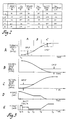
- the fluid-operated devices 82, 84, 88, 90, 116 and 118 are selectively engageable in accordance with the friction element state table of Figure 2 to provide four forward ratios (1st, 2nd, 3rd and 4th) and one reverse ratio (Rev).
- the friction brake 82 (referred to herein as 4th clutch) is supplied with fluid pressure via line D.
- the fluid clutch 84 (referred to herein as D3, or Drive 3 clutch) is supplied with fluid pressure via line C.
- the friction clutch 88 (referred to herein as the forward clutch) is supplied with fluid pressure via line G.
- the friction clutch 90 (referred to herein as 3rd clutch) is supplied with fluid pressure via lines E and F.
- the pressure is supplied via line E to engage the reverse ratio, and via line F to engage the 3rd and 4th ratios.
- the friction brake 116 (referred to herein as 1st/REV clutch) is supplied with fluid pressure via line H.
- the friction band brake 118 (referred to herein as 2nd band) is engaged by a conventional fluid-operated servo 120.
- the 2-1 downshift merely requires release of the 2nd friction band brake 118; the on-coming torque establishing device is the one-way brake 114, which engages automatically.
- the 3-2 downshift requires concurrent engagement of the 2nd friction band brake 118 and release of the 3rd friction clutch 90.
- the 4-3 downshift requires concurrent engagement of the D3 fluid clutch 84 and release of the 4th friction clutch 82.
- the fluid supply elements for the automatic transmission 16 include a conventional (variable displacement) pump (P) 122 driven by the impeller 56 of torque converter 52 and a pressure regulator valve (PRV) 124.
- the pump 122 draws hydraulic fluid from a reservoir 126 and delivers pressurized fluid to line 128.
- Line 128 is connected to PRV 124, which operates in response to a pilot pressure in line 130 to regulate the fluid pressure therein by returning a variable portion of the fluid to the reservoir 126.
- the PRV 124 provides a second regulated fluid pressure in line 132 (hereinafter referred to as converter feed pressure).
- the pilot pressure in line 130 is obtained from line pressure solenoid valve 134, which is pulse-width-modulated by powertrain control module 34 via line 136 to alternately connect line 130 with line pressure in line 128 or with exhaust line 138.
- the duty cycle of pulse-width-modulation thereby controls the line pressure in line 128 and the converter feed pressure in line 132.
- the converter feed pressure in line 132 is applied to torque converter control valve (TCCV) 140, which operates in response to a pilot pressure in line 142 to selectively direct converter feed pressure to line A or line B.
- the pilot pressure in line 142 is obtained from (torque converter clutch) solenoid valve 144, which is controlled by the powertrain control module 34 via line 146 to selectively connect line 142 with line pressure in line 128, the exhaust line 148.
- the solenoid valve 144 is normally operative to bias the TCCV 140 such that converter feed pressure in line 132 is directed to line A, and line B is exhausted to the cooler. In such state, the torque converter clutch 54 is released, and torque converter operation is achieved.
- the solenoid valve 144 is energized to bias the TCCV 140 such that converter feed pressure in line 132 is directed to line B, and line A is exhausted to the cooler.
- Line pressure is also supplied to a manual valve 150, the spool 152 of which is adapted to receive linear mechanical input from the operator of the vehicle via a suitable linkage (not shown).
- the spool 152 is positioned by the operator to select the desired operation of automatic transmission 16 as set forth by the designations P, R, N, D, 3, 2 and 1, which correspond to Park, Reverse, Neutral, Drive, 3rd, 2nd and 1st, respectively.
- the manual valve 150 distributes the line pressure to the various output passages C - H according to the spool position.
- spool 152 is positioned in relation to the N, or Neutral, indication.
- the (forward) friction clutch 88 is exhausted via passage G and exhaust line 154 and the (reverse) friction brake 116 is exhausted via passage H and exhaust line 156.
- Line pressure is supplied to solenoid valves 162, 164, 166 and 170 via lines 168 and 172.
- line pressure is also supplied to the (forward) friction clutch 88 via passage G.
- the (2nd band) solenoid valve 162 is pulse-width-modulated by the powertrain control module 34 via line 174 to control the band apply pressure exerted by the fluid-operated servo 120.
- the (3rd clutch) solenoid valve 164 is pulse-width-modulated by the powertrain control module 34 via line 176 to control the apply pressure of 3rd friction clutch 90.
- the (D3 clutch) solenoid valve 166 is pulse-width-modulated by the powertrain control module 34 via line 178 to control the apply pressure of the D3 fluid clutch 84.
- the (4th clutch) solenoid valve 170 is pulse-width-modulated by the powertrain control module 34 via line 180 to control the apply pressure of the 4th friction brake 82.
- the valving arrangement designated generally by the reference numeral 181, performs 1st/REV timing logic.
- the powertrain control module 34 is computer based and receives engine related input signals TPS and MAP via lines 48 and 32 and various other transmission related inputs via lines 182 - 188.
- An engine speed input signal N e is provided on line 182
- a turbine speed input signal N t is provided on line 184
- a transmission output speed input signal N o is provided on line 186
- a manual valve position signal MV is provided on line 188.
- the various input signals are obtained using conventional transducer technology.
- the position signals on lines 48 and 188 are obtained with conventional potentiometers or position transducers 46 and 192; the pressure signal on line 32 is obtained with a conventional pressure transducer 26; and the speed signals on lines 182 - 186 are obtained with conventional variable reluctance magnetic pickups 194 - 198. Obviously other sensor technologies could be used.
- the powertrain control module 34 includes conventional computer elements including a microcomputer, memory elements for storing operating instructions and data, A/D converter elements for conditioning various analogue inputs, and input/output elements for receiving and sending the various input and output signals.
- the powertrain control module 34 operates as described below to control the operation of the various solenoid-operated valves of automatic transmission 16 via lines 136, 146, 174, 176, 178 and 180.
- Flow diagrams representative of computer programs executed by the microprocessor of powertrain control module 34 in carrying out such control are given in Figures 8, 9, and 10a - 10b.
- Transmission operating parameters are graphically depicted on a common time base as they would occur in the course of an event sequenced downshift according to this invention in Graphs A - E of Figure 3.
- Graph 3A depicts the turbine speed N t ;
- Graph 3B depicts the desired gear slip speed DSLPSPD;
- Graph 3C depicts the actual gear slip speed ASLPSPD;
- Graph 3D depicts the pressure command P(OFG) for the off-going clutching device;
- Graph 3E depicts the pressure command P(ONC) for the on-coming clutching device.
- an event sequenced downshift according to this invention is functionally divided into three phases: A, B and C. Additionally, the designations t0 - t5 appear on the time axes to facilitate the description of the sequence of events in the downshift.
- a relatively high speed ratio THIRD for example, is engaged. Accordingly, the pressure command P(OFG) for the active (off-going) friction clutch 90 is maintained at a relatively high steady state value as seen in Graph 3D.
- Such pressure command is obtained from a predetermined and torque dependent schedule designed to substantially prevent clutch slippage.
- the powertrain control module 34 commands a 3-2 downshift, marking the beginning of the A-Phase as designated in Figure 3.
- the pressure command P(OFG) for the off-going friction clutch 90 is progressively reduced according to the predetermined torque and time dependent schedule of Figure 4, as seen in Graph 3D.
- the pressure schedule shown in Figure 4 is matched to the steady state pressure schedule referred to above so that the initial pressure command P(OFG) obtained from the A-Phase portion of Figure 4 (at time t0) corresponds with the steady state pressure command in effect prior to the shift.
- the on-coming clutch engagement mechanism (fluid-operated servo 120) is also filled or prepared for torque transmission during the A-Phase of the shift.
- the relation between the initiation of the off-going clutch pressure reduction (time t0) and the start of fill (time t1) is governed by a term referred to herein as SHIFT DELTA.
- SHIFT DELTA is defined as the interval (t1 - t0), and is scheduled as a function of the turbine speed change DELTURB expected to occur during the shift. This, in turn, is calculated at the initiation of the shift in relation to the turbine speed AGINPSPD in effect at the start of the shift, the transmission output speed N o and the speed ratio defined by the desired gear.
- SHIFT DELTA and DELTURB are empirically determined, as graphically depicted in Figure 5, so that the on-coming clutch is filled and prepared for engagement by the time the turbine speed is within a reference amount CREF of its postshift value DGINPSPD.
- the pressure command P(ONC) is reduced to a low level P lo , as indicated at time t2, sufficient only to maintain the on-coming clutch prepared for engagement.
- the friction clutch 90 With the reduction in the pressure command P(OFG), the friction clutch 90 begins to slip as seen by the actual (old) gear slip speed ASLPSPD in Graph 3C. This enables the internal combustion engine 12 to increase the turbine speed N t as seen in Graph 3A.
- the reference slip level BREF is empirically determined in relation to the change DELTURB in turbine speed N t during the shift, as graphically depicted in Figure 6, so that the consequent rate of change in turbine speed is within a predetermined acceleration range at the onset of the B-Phase.
- the reference BREF may be defined as a specified amount of turbine speed increase, as indicated in Graph 3A.
- the B-Phase pressure command P(OFG) is obtained by freezing the time variable SHFTME at the A-Phase-to-B-Phase transition.
- the pressure command P(OFG) retains its torque dependency, but does not decrease with time spent in the B-Phase.
- the desired gear slip speed DSLPSPD decreases, as seen in Graph 3B.
- a slip speed of zero indicates synchronization of the turbine speed N t with the desired gear.
- the slip speed falls below a reference speed CREF, signaling the end of the B-Phase and the beginning of the C-Phase.
- the reference CREF may alternately be defined as a specified amount of remaining turbine speed increase, as indicated in Graph 3A.
- the pressure command P(OFG) is progressively reduced to release the off-going friction clutch 90 as seen in Graph 3D, and the pressure command P(ONC) is progressively increased to engage the on-coming friction band brake 118 as seen in Graph 3E.
- the pressure command P(OFG) is reduced in accordance with the schedule graphically depicted in the C-Phase region of Figure 4. As indicated in that Figure, the schedule provides a multiplier MULT for the pressure command in effect during the B-Phase of the shift. The multiplier starts at unity and decreases to zero with elapsed time SHFTME.
- the pressure command P(ONC) is increased in accordance with the schedule graphically depicted in Figure 7 as a function of the input torque variable T v and the time spent in the C-Phase CTME.
- the shift is complete when the pressure commands P(OFG) and P(ONC) reach their final values.
- Friction clutch 90 and friction band brake 118 define torque establishing devices.
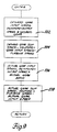
- Figures 8, 9 and 10a - 10b depict flow diagrams representative of computer program instructions executed by the computer based powertrain control module 34 of Figure 1 in carrying out the control functions of this invention.
- Figure 8 depicts a main loop or executive program setting forth the major steps of the control.
- Figures 9 and 10a - 10b depict various of such steps in detail.
- the reference numeral 310 generally designates a series of instructions executed at the initiation of each period of vehicle operation for initializing the various timers, registers and variables of the powertrain control module 34.
- the instruction blocks 312 - 324 are repeatedly executed in sequence as designated by the flow diagram lines connecting such instruction blocks and the return line 326.
- Instruction block 312 serves to read and condition the various input signals applied to powertrain control module 34, and updates (increments) various control unit timers.
- Instruction block 314 calculates various terms used in the control algorithms, including the input torque variable T v .
- An algebraic expression which may be used to calculate the term T v is given in US-A-4 653 350.
- Instruction block 316 schedules a line or operating pressure command for the pressure regulator valve PRV in accordance with the input torque variable T v , and the instruction block 318 determines the desired speed ratio, R des .
- the desired speed ratio R des may be determined in accordance with a number of inputs including throttle position, vehicle speed and manual valve position. In transmission control, this function is generally referred to as shift pattern generation.
- Instruction block 320 determines various ratio-based terms used in connection with the event sequenced downshift control of this invention, and instruction block 322 determines the clutching device pressure commands for effecting a ratio shift, if required. The pressure commands for nonshifting clutching devices are also determined. Expanded descriptions of the instruction blocks 320 and 322 are given in the flow diagrams of Figures 9 and 10a - 10b, respectively, as indicated.
- Instruction block 324 converts the clutching device and PRV pressure commands to PWM duty cycles based on the operating characteristics of the various actuators (empirically determined), and energizes the actuator coils accordingly.
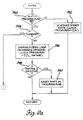
- the instruction blocks 332 -338 are executed in sequence to determine various ratio-based terms used in connection with the event sequenced downshift of this invention.
- the desired gear input speed is computed at instruction block 332 according to the product of the transmission output speed N o and the speed ratio of the desired speed ratio R des .
- the desired gear slip speed DSLPSPD is computed at instruction block 334 according to the difference of the desired gear input speed and the turbine speed N t .
- the actual (old) gear input speed is computed at instruction block 336 according to the product of the transmission output speed N o and the speed ratio of the present (old) ratio R.
- the actual (old) gear slip speed ASLPSPD is computed at instruction block 338 according to the difference between the turbine speed N t and the actual gear input speed completed at instruction block 336.
- decision block 340 is first executed to determine if the SHIFT IN PROGRESS flag is set. This flag is set by the desired ratio scheduling routine, described in reference to instruction block 318 of the main flow diagram of Figure 8, whenever the desired speed ratio R des differs from the actual (present) ratio R. As indicated below, the SHIFT IN PROGRESS flag is reset at the completion of the commanded shift.
- instruction block 342 is executed to schedule the steady state clutch pressures so as to maintain engagement of the currently established ratio R, completing the routine.
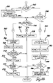
- decision block 344 is executed to determine if the required shift is a downshift. If not, an upshift is required and instruction block 346 is executed to schedule the on-coming and off-going clutch pressures P(ONC) and P(OFG) as an open-loop function of the input torque variable T v and the elapsed time of the shift, designated by the term SHFTME. When the term SHFTME exceeds a reference, MAXTIME, indicative of shift completion, as determined at decision block 348, instruction block 350 is executed to reset the SHIFT IN PROGRESS flag. If the required shift is a downshift, the flow diagram set forth in Figure 10b is executed to carry out an event sequenced downshift according to this invention, as indicated by the circled numeral 1.
- decision block 352 is first executed to determine if the A PHASE flag is set. If not, the shift is just starting and instruction block 354 is executed to initialize the term SHIFT DELTA, defined above in reference to Graph 3E, to set the A PHASE flag and to reset the elapsed shift time term SHFTME. In the course of the shift, the decision block 352 will thereafter be answered in the affirmative, signaling the execution of decision block 356.
- the decision block 356 determines if the desired gear slip speed DSLPSPD is less than a synchronization level threshold LVLCTHR defined above in reference to Graph 3A.
- decision block 356 will be answered in the negative, signaling the execution of decision block 358.
- the decision block 358 determines if the actual (present) gear slip speed ASLPSPD is less than the B Phase slip level speed reference, BREF, defined above in reference to Graph 3A.
- instruction block 366 is first executed to increment the elapsed shift time term SHFTME. Then, instruction block 368 is executed to determine the pressure command P(OFG) for the off-going clutch. As indicated above in reference to the graph of Figure 4, the off-going pressure command P(OFG) is determined as a two-dimensional function of the input torque variable T v and the elapsed shift time term SHFTME.
- instruction block 372 is executed to set the pressure command P(ONC) for the on-coming clutch equal to the transmission line pressure P line for initiating the fill phase of the clutch.
- P(ONC) is determined as a function of the change in turbine speed for the shift.
- instruction block 378 is executed to determine the off-going pressure command P(OFG) as a function of the input torque variable T v and the elapsed shift time term SHFTME.
- the time term used in scheduling P(OFG) during the B-Phase is frozen at the end of the A-Phase.
- the term SHFTME is not incremented during the B-Phase of the shift.
- the pressure command P(ONC) for the on-coming clutch is maintained at the relatively low level P lo to maintain the on-coming clutch in a filled condition.
- instruction block 380 is first executed to increment the elapsed shift time term SHFTME and a separate elapsed C-Phase time term CTME. Then, instruction blocks 382 and 384 are executed to determine the pressure commands P(ONC) and P(OFG) for the on-coming and off-going clutches. As indicated above in reference to Figure 7, P(ONC) is determined as a function of the input torque variable T v and the time in the C-Phase of the shift CTME.
- P(OFG) is determined according to the product of P(OFG) at the end of the B-Phase and a multiplier MULT determined as a function of the input torque variable T v and the elapsed shift time SHFTME.
- instruction block 388 is executed to reset the SHIFT IN PROGRESS flag, completing the C-Phase and the event sequenced downshift routine.
Landscapes
- Engineering & Computer Science (AREA)
- General Engineering & Computer Science (AREA)
- Physics & Mathematics (AREA)
- Fluid Mechanics (AREA)
- Mechanical Engineering (AREA)
- Control Of Transmission Device (AREA)
- Structure Of Transmissions (AREA)
Claims (2)
- Verfahren zum Betreiben von Drehmomenteinrichtgeräten (90, 118) eines Automatikgetriebes (16) zum Herabschalten des Automatikgetriebes (16) von einem oberen (3.) Drehzahlverhältnis-Mechanismus zu einem unteren (2.) Drehzahlverhältnis-Mechanismus, wenn das Herabschalten zur Erfüllung einer Anforderung des Fahrers benötigt ist, wobei die Drehmomenteinrichtgeräte (90, 118) wahlweise in Eingriff bringbar sind, um Motordrehmoment eines mit dem Automatikgetriebe (16) verbundenen Motors (12) durch ihre jeweiligen Drehzahlverhältnis-Mechanismen zu übertragen, wobei das dem unteren (2.) Drehzahlverhältnis-Mechanismus zugeordnete Drehmoment-Einrichtgerät (118) Eingriffsmittel enthält, die im wesentlichen mit Fluid gefüllt werden müssen, bevor der Eingriff des Drehmoment-Einrichtgerätes (118) bewirkt werden kann, und das Verfahren die Schritte enthält
der dem Drehmoment-Einrichtgerät (90), das dem oberen (3.) Drehzahlverhältnis-Mechanismus zugeordnet ist, zugeführte Fluiddruck wird fortschreitend reduziert, wodurch dem Motor (12) die Erhöhung der Getriebeeingangs-Drehzahl erlaubt wird; die fortschreitende Reduzierung des dem Drehmoment-Einrichtgerät (90), das dem oberen (3.) Drehzahlverhältnis-Mechanismus zugeordnet ist, zugeführten Fluiddrucks wird unterbrochen, wenn der darüber auftretende Schlupf einen ersten Referenzwert übersteigt; und die jeweils dem unteren (2.) und dem oberen (3.) Drehzahlverhältnis-Mechanismus zugeordneten Drehmoment-Einrichtgeräte (118, 90) werden fortschreitend in Eingriff gebracht bzw. aus diesen gelöst;
dadurch gekennzeichnet, daß das Füllen des Eingriffsmittels eingeleitet wird in Relation zu der Änderung der Getriebe-Eingangsdrehzahl, die während des Herabschaltens erwartet wird, und einer Abschätzung der zu ihrem Füllen erforderlichen Zeit, so daß das Eingriffsmittel im wesentlichen vor dem erforderlichen Eingreifen seines zugeordneten Drehmoment-Einrichtgeräts gefüllt ist; daß der dem Eingriffsmittel zugeführte Druck nach Ablauf der geschätzten Füllzeit bis zu einem Pegel reduziert wurd, der ausreicht, das Eingriffsmittel in einem im wesentlichen gefüllten Zustand zu erhalten, bis der Eingriff seines zugeordneten Drehmoment-Einrichtgeräts erforderlich ist; und daß der Schritt des zunehmenden Eingreifens bzw. zunehmenden Lösens beginnt, wenn der Schlupf über dem dem unteren (2.) Drehzahlverhältnis-Mechanismus zugeordneten Drehmoment-Einrichtgerät (118) unter einen zweiten Referenzwert abfällt, der mit Bezug auf dessen Eingriffszeitpunkt ausgewählt ist, wodurch die Getriebe-Eingangsdrehzahl im wesentlichen einen Nachschaltwert erreicht zum Zeitpunkt eines solchen Eingriffes bzw. Lösens, wodurch sich eine reduzierte schaltungsbezogene Ausgangsdrehmoment-Störung ergibt. - Verfahren nach Anspruch 1, bei dem der erste Referenzwert in Relation zu der Getriebe-Eingangsdrehzahl-Änderung ausgewählt wird, deren Auftreten während des Herabschaltens zum Erreichen eines erwünschten Pegels der Getriebe-Eingangsdrehzahl-Beschleunigung erwartet wird.
Applications Claiming Priority (2)
| Application Number | Priority Date | Filing Date | Title |
|---|---|---|---|
| US07/136,417 US4796490A (en) | 1987-12-22 | 1987-12-22 | Event sequenced clutch-to-clutch downshift for an electronically controlled transmission |
| US136417 | 2002-05-01 |
Publications (3)
| Publication Number | Publication Date |
|---|---|
| EP0322111A2 EP0322111A2 (de) | 1989-06-28 |
| EP0322111A3 EP0322111A3 (en) | 1990-02-14 |
| EP0322111B1 true EP0322111B1 (de) | 1993-05-26 |
Family
ID=22472771
Family Applications (1)
| Application Number | Title | Priority Date | Filing Date |
|---|---|---|---|
| EP88311070A Expired - Lifetime EP0322111B1 (de) | 1987-12-22 | 1988-11-23 | Ereignisfolgenbedingtes Kupplung-zu-Kupplung-Herunterschalten für ein elektronisch gesteuertes automatisches Getriebe |
Country Status (4)
| Country | Link |
|---|---|
| US (1) | US4796490A (de) |
| EP (1) | EP0322111B1 (de) |
| JP (1) | JPH0633816B2 (de) |
| DE (1) | DE3881362T2 (de) |
Families Citing this family (51)
| Publication number | Priority date | Publication date | Assignee | Title |
|---|---|---|---|---|
| JPS63284039A (ja) * | 1987-05-14 | 1988-11-21 | Nissan Motor Co Ltd | 車両の走行制御装置 |
| JPH0792140B2 (ja) * | 1988-04-15 | 1995-10-09 | 日産自動車株式会社 | 自動変速機のライン圧制御装置 |
| JPH01275938A (ja) * | 1988-04-26 | 1989-11-06 | Honda Motor Co Ltd | 自動変速機の変速制御方法 |
| US4905545A (en) * | 1988-04-29 | 1990-03-06 | Chrysler Motors Corporation | Method of controlling the speed change of a kickdown shift for an electronic automatic transmission system |
| JPH0246365A (ja) * | 1988-08-08 | 1990-02-15 | Nissan Motor Co Ltd | 自動変速機のライン圧制御装置 |
| JPH0792142B2 (ja) * | 1989-01-31 | 1995-10-09 | 日産自動車株式会社 | 自動変速機の変速液圧制御装置 |
| JP2848401B2 (ja) * | 1989-02-28 | 1999-01-20 | 日産自動車株式会社 | 自動変速機の変速液圧制御装置 |
| JP2739121B2 (ja) * | 1989-09-05 | 1998-04-08 | トヨタ自動車株式会社 | 自動変速機の変速制御装置 |
| JP2966003B2 (ja) * | 1989-09-06 | 1999-10-25 | トヨタ自動車株式会社 | 自動変速機の変速制御装置 |
| US5014573A (en) * | 1989-12-11 | 1991-05-14 | General Motors Corporation | Double transition upshift control in an automatic transmission |
| US5046174A (en) * | 1990-01-11 | 1991-09-03 | General Motors Corporation | Method of clutch-to-clutch closed throttle downshift in an automatic transmission |
| US5070747A (en) * | 1989-12-26 | 1991-12-10 | General Motors Corporation | Adaptive powered downshift control of an automatic transmission |
| EP0435372B1 (de) * | 1989-12-26 | 1994-11-09 | General Motors Corporation | Verfahren zum Steuern des Gangwechsels in automatischen Getrieben |
| US5029494A (en) * | 1989-12-26 | 1991-07-09 | General Motors Corporation | Control method of clutch-to-clutch powered downshift in an automatic transmission |
| EP0435377B1 (de) * | 1989-12-26 | 1995-04-05 | General Motors Corporation | Verfahren zum Steuern des Gangwechsels in automatischen Getrieben |
| US4989477A (en) * | 1990-01-11 | 1991-02-05 | General Motors Corporation | Double transition closed throttle downshift control in an automatic transmissions |
| US5046383A (en) * | 1990-07-16 | 1991-09-10 | General Motors Corporation | Acceleration-based control of power-on clutch-to-clutch upshifting in an automatic transmission |
| US5113343A (en) * | 1990-08-02 | 1992-05-12 | General Motors Corporation | Sequenced control of double transition powered downshifting in an automatic transmission |
| US5036729A (en) * | 1990-10-23 | 1991-08-06 | Saturn Corporation | Coast-sync-coast downshift control method for clutch-to-clutch transmission shifting |
| US5079970A (en) * | 1990-10-24 | 1992-01-14 | General Motors Corporation | Acceleration-based control of power-on downshifting in an automatic transmission |
| US5038636A (en) * | 1991-02-07 | 1991-08-13 | General Motors Corporation | Double transition downshift control for an automatic transmission |
| US5086665A (en) * | 1991-06-27 | 1992-02-11 | Saturn Corporation | Adaptive shift pressure characterization of an electronically controlled automatic transmission |
| US5119695A (en) * | 1991-06-27 | 1992-06-09 | Saturn Corporation | Open-loop clutch-to-clutch upshift control having clutch overlap regulation |
| US5443427A (en) * | 1992-06-23 | 1995-08-22 | Honda Giken Kogyo Kabushiki Kaisha | Apparatus for controlling automatic transmission |
| US5343782A (en) * | 1992-08-31 | 1994-09-06 | General Motors Corporation | Anti-flare method using offgoing slip speed and rate of change of slip-speed to determine pressure compensation for incoming clutch |
| US5383825A (en) * | 1993-05-25 | 1995-01-24 | Ford Motor Company | Electronic shift controller for a multiple ratio automotive transmission |
| GB2286641B (en) * | 1994-02-17 | 1998-01-07 | Acg France | Method and apparatus for controlling a gear change in an automatic transmission |
| DE4405806A1 (de) * | 1994-02-23 | 1995-08-24 | Zahnradfabrik Friedrichshafen | Verfahren zum Steuern eines automatischen Schaltgetriebes |
| JP3571409B2 (ja) * | 1995-04-03 | 2004-09-29 | 本田技研工業株式会社 | 自動変速機の変速制御装置 |
| GB2327990B (en) * | 1995-04-13 | 1999-04-07 | Caterpillar Inc | Method for determining the fill time of a transmission clutch |
| US5580332A (en) * | 1995-04-13 | 1996-12-03 | Caterpillar Inc. | Method for determining the fill time of a transmission clutch |
| JP4012581B2 (ja) * | 1996-01-08 | 2007-11-21 | 本田技研工業株式会社 | 自動変速機の変速制御方法 |
| JP3785672B2 (ja) * | 1996-03-31 | 2006-06-14 | マツダ株式会社 | 自動変速機の制御装置 |
| JPH09292013A (ja) * | 1996-04-25 | 1997-11-11 | Toyota Motor Corp | 自動変速機の変速制御装置 |
| EP1302705B1 (de) * | 1996-09-25 | 2004-07-07 | Honda Giken Kogyo Kabushiki Kaisha | Steuergerät für hydraulisch gesteuertes Fahrzeuggetriebe |
| JP3555386B2 (ja) * | 1997-06-25 | 2004-08-18 | トヨタ自動車株式会社 | 自動変速機の変速制御装置 |
| US6115661A (en) * | 1998-04-09 | 2000-09-05 | Caterpillar Inc. | End-of-fill detector for a fluid actuated clutch |
| US5950789A (en) * | 1998-04-27 | 1999-09-14 | Caterpillar Inc. | End of fill detector for a fluid actuated clutch |
| JP3797041B2 (ja) * | 1999-10-08 | 2006-07-12 | トヨタ自動車株式会社 | 自動変速機の油圧制御装置 |
| US6368249B1 (en) | 2000-05-19 | 2002-04-09 | General Motors Corporation | Driver responsive power-on downshift control |
| US6415213B1 (en) | 2000-05-19 | 2002-07-02 | General Motors Corporation | Model-based control of an automatic transmission power-on downshift |
| US6319170B1 (en) | 2000-05-19 | 2001-11-20 | General Motors Corporation | Model-based engine torque control for power-on downshifting in an automatic transmission |
| US6656087B1 (en) * | 2002-06-11 | 2003-12-02 | General Motors Corporation | Multi-stage skip downshift control for an automatic transmission |
| DE10231817A1 (de) * | 2002-07-15 | 2004-02-05 | Zf Friedrichshafen Ag | Verfahren zur Steuerung eines Gangwechsels in einem Kraftfahrzeug-Automatgetriebe |
| US20060219509A1 (en) * | 2005-03-31 | 2006-10-05 | Caterpillar Inc. | System and method for controlling engagement of a clutch |
| US8682555B2 (en) * | 2009-03-17 | 2014-03-25 | Flanders' Mechatronics Technology Centre Vzw | Method for controlling a torque transmitting device with learning function |
| US20130253789A1 (en) * | 2012-03-21 | 2013-09-26 | Anthony K. Johnson | Method For Hydraulically Filling A Clutch Without Using A Calibration Routine |
| US8965653B2 (en) * | 2013-07-24 | 2015-02-24 | GM Global Technology Operations LLC | Partial prefill of clutch for coast downshift conditions in a vehicle |
| US9308908B2 (en) | 2013-10-10 | 2016-04-12 | Ford Global Technologies, Llc | Method of shifting a transmission |
| KR101567231B1 (ko) * | 2014-07-29 | 2015-11-06 | 현대자동차주식회사 | 하이브리드 자동차의 엔진클러치 제어 장치 및 방법 |
| JP6565813B2 (ja) * | 2016-07-20 | 2019-08-28 | トヨタ自動車株式会社 | 自動変速機の制御装置 |
Family Cites Families (16)
| Publication number | Priority date | Publication date | Assignee | Title |
|---|---|---|---|---|
| US4102222A (en) * | 1977-01-03 | 1978-07-25 | Borg-Warner Corporation | Transmission control system |
| DE2835051C2 (de) * | 1978-08-10 | 1984-06-28 | Zahnradfabrik Friedrichshafen Ag, 7990 Friedrichshafen | Vorrichtung zur Regelung des übertragbaren Momentes von Reibelementen |
| JPS5547041A (en) * | 1978-09-30 | 1980-04-02 | Aisin Warner Ltd | Controller for automatic speed change gear |
| DE3010865A1 (de) * | 1980-03-21 | 1981-10-01 | Robert Bosch Gmbh, 7000 Stuttgart | Vorrichtung zur steuerung eines automatischen stufengetriebes in kraftfahrzeugen |
| JPS57146941A (en) * | 1981-03-06 | 1982-09-10 | Aisin Warner Ltd | Oil pressure controller for automatic speed changer |
| JPS57163732A (en) * | 1981-03-31 | 1982-10-08 | Mitsubishi Motors Corp | Control apparatus of automatic speed change gear |
| JPS5947552A (ja) * | 1982-09-10 | 1984-03-17 | Mitsubishi Motors Corp | 自動変速機の制御装置 |
| JPS6145153A (ja) * | 1984-08-06 | 1986-03-05 | Mazda Motor Corp | 自動変速機の油圧制御装置 |
| JPS61241558A (ja) * | 1985-04-18 | 1986-10-27 | Toyota Motor Corp | 車輌用自動変速機の変速制御方法 |
| US4690017A (en) * | 1985-07-01 | 1987-09-01 | Toyota Jidosha Kabushiki Kaisha | Shift control system of automatic transmission |
| US4709596A (en) * | 1985-10-31 | 1987-12-01 | Mazda Motor Corporation | Control of a vehicle automatic transmission |
| JPS6276026U (de) * | 1985-11-01 | 1987-05-15 | ||
| US4653350A (en) * | 1985-11-29 | 1987-03-31 | General Motors Corporation | Adaptive direct pressure shift control for a motor vehicle transmission |
| US4707789A (en) * | 1985-11-29 | 1987-11-17 | General Motors Corporation | Adaptive direct pressure shift control for a motor vehicle transmission |
| JPS62165051A (ja) * | 1986-01-13 | 1987-07-21 | Toyota Motor Corp | 自動変速機の制御方法 |
| US4653351A (en) * | 1986-02-12 | 1987-03-31 | General Motors Corporation | Clutch-to-clutch power-on downshifting in a motor vehicle automatic transmission |
-
1987
- 1987-12-22 US US07/136,417 patent/US4796490A/en not_active Expired - Lifetime
-
1988
- 1988-11-23 DE DE8888311070T patent/DE3881362T2/de not_active Expired - Lifetime
- 1988-11-23 EP EP88311070A patent/EP0322111B1/de not_active Expired - Lifetime
- 1988-12-22 JP JP63324720A patent/JPH0633816B2/ja not_active Expired - Lifetime
Also Published As
| Publication number | Publication date |
|---|---|
| EP0322111A2 (de) | 1989-06-28 |
| JPH023770A (ja) | 1990-01-09 |
| EP0322111A3 (en) | 1990-02-14 |
| JPH0633816B2 (ja) | 1994-05-02 |
| US4796490A (en) | 1989-01-10 |
| DE3881362T2 (de) | 1993-09-09 |
| DE3881362D1 (de) | 1993-07-01 |
Similar Documents
| Publication | Publication Date | Title |
|---|---|---|
| EP0322111B1 (de) | Ereignisfolgenbedingtes Kupplung-zu-Kupplung-Herunterschalten für ein elektronisch gesteuertes automatisches Getriebe | |
| US4724723A (en) | Closed loop shift quality control system | |
| EP0231994B1 (de) | Steuereinrichtung zum Herunterschalten eines Fahrzeuggetriebes im Schiebebetrieb zwischen zwei mittels Kupplungen schaltbaren Übersetzungen | |
| US4989477A (en) | Double transition closed throttle downshift control in an automatic transmissions | |
| US5046178A (en) | Control method for automatic transmission garage shifts | |
| US5046174A (en) | Method of clutch-to-clutch closed throttle downshift in an automatic transmission | |
| US5014573A (en) | Double transition upshift control in an automatic transmission | |
| EP0235892B1 (de) | Herunterschalten unter Last von Kupplung zu Kupplung in einem automatischen Getriebe eines Kraftfahrzeugs | |
| US5046383A (en) | Acceleration-based control of power-on clutch-to-clutch upshifting in an automatic transmission | |
| US5113343A (en) | Sequenced control of double transition powered downshifting in an automatic transmission | |
| US5058460A (en) | Clutch-to-clutch control in an automatic transmission | |
| CA2026480C (en) | Method of detecting clutch tie-up during transmission shifting | |
| US5029494A (en) | Control method of clutch-to-clutch powered downshift in an automatic transmission | |
| US5036729A (en) | Coast-sync-coast downshift control method for clutch-to-clutch transmission shifting | |
| EP0770800B1 (de) | Ein automatisches Getriebe | |
| EP0707162A2 (de) | Automatisches Mehrganggetriebe und Steuersystem dafür | |
| US7559876B2 (en) | Method of detecting and preventing tie-up during a double transition up-shift | |
| CA2097689C (en) | Transmission detent shift control with acceleration-based compensation | |
| EP0800124B1 (de) | Adaptives Gangschaltungssteuersystem basiert auf unscharfer Logik | |
| EP0626529A2 (de) | Kraftfahrzeuggetriebe | |
| US6254510B1 (en) | Coasting downshift control strategy for a multiple-ratio automatic transmission | |
| EP0435372B1 (de) | Verfahren zum Steuern des Gangwechsels in automatischen Getrieben | |
| US5596495A (en) | Gearshift controller for automatic transmission | |
| JPH04102761A (ja) | トルク伝達装置の流体充填時間決定方法及びそのための装置 | |
| EP0435376B1 (de) | Verfahren zur Steuerung des Gangwechsels in automatischen Getrieben |
Legal Events
| Date | Code | Title | Description |
|---|---|---|---|
| PUAI | Public reference made under article 153(3) epc to a published international application that has entered the european phase |
Free format text: ORIGINAL CODE: 0009012 |
|
| AK | Designated contracting states |
Kind code of ref document: A2 Designated state(s): DE FR GB |
|
| PUAL | Search report despatched |
Free format text: ORIGINAL CODE: 0009013 |
|
| AK | Designated contracting states |
Kind code of ref document: A3 Designated state(s): DE FR GB |
|
| 17P | Request for examination filed |
Effective date: 19900427 |
|
| 17Q | First examination report despatched |
Effective date: 19910827 |
|
| GRAA | (expected) grant |
Free format text: ORIGINAL CODE: 0009210 |
|
| AK | Designated contracting states |
Kind code of ref document: B1 Designated state(s): DE FR GB |
|
| REF | Corresponds to: |
Ref document number: 3881362 Country of ref document: DE Date of ref document: 19930701 |
|
| ET | Fr: translation filed | ||
| PLBE | No opposition filed within time limit |
Free format text: ORIGINAL CODE: 0009261 |
|
| STAA | Information on the status of an ep patent application or granted ep patent |
Free format text: STATUS: NO OPPOSITION FILED WITHIN TIME LIMIT |
|
| 26N | No opposition filed | ||
| REG | Reference to a national code |
Ref country code: GB Ref legal event code: IF02 |
|
| PGFP | Annual fee paid to national office [announced via postgrant information from national office to epo] |
Ref country code: DE Payment date: 20071115 Year of fee payment: 20 |
|
| PGFP | Annual fee paid to national office [announced via postgrant information from national office to epo] |
Ref country code: FR Payment date: 20071108 Year of fee payment: 20 Ref country code: GB Payment date: 20071121 Year of fee payment: 20 |
|
| REG | Reference to a national code |
Ref country code: GB Ref legal event code: PE20 Expiry date: 20081122 |
|
| PG25 | Lapsed in a contracting state [announced via postgrant information from national office to epo] |
Ref country code: GB Free format text: LAPSE BECAUSE OF EXPIRATION OF PROTECTION Effective date: 20081122 |