EP0321908B1 - Appareil pour la vaporisation de désinfectants - Google Patents
Appareil pour la vaporisation de désinfectants Download PDFInfo
- Publication number
- EP0321908B1 EP0321908B1 EP88121238A EP88121238A EP0321908B1 EP 0321908 B1 EP0321908 B1 EP 0321908B1 EP 88121238 A EP88121238 A EP 88121238A EP 88121238 A EP88121238 A EP 88121238A EP 0321908 B1 EP0321908 B1 EP 0321908B1
- Authority
- EP
- European Patent Office
- Prior art keywords
- gas generator
- gas
- generator according
- inner tube
- shell
- Prior art date
- Legal status (The legal status is an assumption and is not a legal conclusion. Google has not performed a legal analysis and makes no representation as to the accuracy of the status listed.)
- Expired - Lifetime
Links
Images

Classifications
-
- B—PERFORMING OPERATIONS; TRANSPORTING
- B01—PHYSICAL OR CHEMICAL PROCESSES OR APPARATUS IN GENERAL
- B01D—SEPARATION
- B01D1/00—Evaporating
- B01D1/30—Accessories for evaporators ; Constructional details thereof
- B01D1/305—Demister (vapour-liquid separation)
-
- A—HUMAN NECESSITIES
- A61—MEDICAL OR VETERINARY SCIENCE; HYGIENE
- A61L—METHODS OR APPARATUS FOR STERILISING MATERIALS OR OBJECTS IN GENERAL; DISINFECTION, STERILISATION OR DEODORISATION OF AIR; CHEMICAL ASPECTS OF BANDAGES, DRESSINGS, ABSORBENT PADS OR SURGICAL ARTICLES; MATERIALS FOR BANDAGES, DRESSINGS, ABSORBENT PADS OR SURGICAL ARTICLES
- A61L2/00—Disinfection or sterilisation of materials or objects, in general; Accessories therefor
- A61L2/16—Disinfection or sterilisation of materials or objects, in general; Accessories therefor using chemical substances
- A61L2/20—Gaseous substances, e.g. vapours
-
- B—PERFORMING OPERATIONS; TRANSPORTING
- B01—PHYSICAL OR CHEMICAL PROCESSES OR APPARATUS IN GENERAL
- B01B—BOILING; BOILING APPARATUS ; EVAPORATION; EVAPORATION APPARATUS
- B01B1/00—Boiling; Boiling apparatus for physical or chemical purposes ; Evaporation in general
- B01B1/005—Evaporation for physical or chemical purposes; Evaporation apparatus therefor, e.g. evaporation of liquids for gas phase reactions
-
- B—PERFORMING OPERATIONS; TRANSPORTING
- B01—PHYSICAL OR CHEMICAL PROCESSES OR APPARATUS IN GENERAL
- B01D—SEPARATION
- B01D1/00—Evaporating
- B01D1/0011—Heating features
- B01D1/0017—Use of electrical or wave energy
-
- B—PERFORMING OPERATIONS; TRANSPORTING
- B01—PHYSICAL OR CHEMICAL PROCESSES OR APPARATUS IN GENERAL
- B01D—SEPARATION
- B01D3/00—Distillation or related exchange processes in which liquids are contacted with gaseous media, e.g. stripping
- B01D3/34—Distillation or related exchange processes in which liquids are contacted with gaseous media, e.g. stripping with one or more auxiliary substances
- B01D3/343—Distillation or related exchange processes in which liquids are contacted with gaseous media, e.g. stripping with one or more auxiliary substances the substance being a gas
- B01D3/346—Distillation or related exchange processes in which liquids are contacted with gaseous media, e.g. stripping with one or more auxiliary substances the substance being a gas the gas being used for removing vapours, e.g. transport gas
-
- Y—GENERAL TAGGING OF NEW TECHNOLOGICAL DEVELOPMENTS; GENERAL TAGGING OF CROSS-SECTIONAL TECHNOLOGIES SPANNING OVER SEVERAL SECTIONS OF THE IPC; TECHNICAL SUBJECTS COVERED BY FORMER USPC CROSS-REFERENCE ART COLLECTIONS [XRACs] AND DIGESTS
- Y10—TECHNICAL SUBJECTS COVERED BY FORMER USPC
- Y10S—TECHNICAL SUBJECTS COVERED BY FORMER USPC CROSS-REFERENCE ART COLLECTIONS [XRACs] AND DIGESTS
- Y10S261/00—Gas and liquid contact apparatus
- Y10S261/65—Vaporizers
Definitions
- the present invention relates to a gas generator for vaporizing a disinfectant by dropping it on a heating element, which apparatus is applied to such the technical field, of disinfection.
- a gas generator for vaporizing a disinfectant by dropping it on a heating element which apparatus is applied to such the technical field, of disinfection.
- a packing material including a container or the like is sterilized or disinfected by using disinfection gas
- a material to be sterilized is sterilized by dropping a disinfection liquid on the heating element to vaporize, introducing the vaporized infection gas to the surface of the material to be sterilized by a heated carrier gas and condensing the carried disinfection gas on the surface of the material to be sterilized by a heated carrier gas and condensing the carried disinfection gas on the surface of the material to be sterilized.
- hydrogen peroxide is used as a disinfection gas and a spray vaporization method.
- spray vaporization method it is necessary to provide a system for pressurizing hydrogen peroxide and a spray chamber. Some trouble in process such as blinding of nozzles and hunting of spray is probable to occur.
- Japanese Patent Application 174235/86 discloses a gas generator according to the preamble of claim 1.
- the known gas generator adopts a drop vaporization method in which hydrogen peroxide is vaporized by dropping it on the heating unit.
- a board heating type or a falling heating type is proposed as the construction of said heating unit.
- a stainless steel net is provided on a heat transfer block as an evaporation surface, a blow-off opening for a heated carrier air is provided above the evaporation surface parallel to the surface of the heat transfer block, the heated air is blown from the opening to promote the evaporation of hydrogen peroxide and the hydrogen peroxide gas is carried.
- a filter means is provided adjacent to the outlet of the vaporization chamber so as to prevent droplet splashes of hydrogen peroxide caused by increase of the carrier air or by the spheroidal phenomenon on the heated surface from being accompanied with the hydrogen peroxide gas.
- a stainless steel net is provided as a vaporization surface in a vertical double heat pipe, a blow-off opening for heated carrier air is provided below said double heat pipes and the heated air is blown up along the interval between the double heat pipes.
- Other features are substantially same as those of the board heating type unit previously explained.
- the drop vaporization method presents some difficulties in controlling the rate of supply of the material to be sterilized to the sterilizing apparatus and the drying conditions of the material to be sterilized, unless the hydrogen peroxide gas not accompanied with the droplet splashes can be supplied on the surface of the material to be sterilized. That is, if the droplet splashes of hydrogen peroxide exists with the hydrogen peroxide gas, the gas density thereof becomes inhomogenuous, resulting in uneven sterilization of the surface to be sterilized.
- the hydrogen peroxide which is not evaporized due to inhomogenuous heating often accumulates at the bottom of the apparatus. Further there also occurs large heat loss caused by the large heating area. Additionally, the known filter means for preventing the drop splash of hydrogen peroxide accompanied with the hydrogen peroxide gas is not sufficient enough to make the vaporized hydrogen peroxide gas uniform.
- the hot surface is extended vertically, and therefore it leaves same disadvantages as those of the board heating type unit.
- the object of the present invention is to provide a disinfectant vaporizing apparatus or gas generator for dropping disinfection liquid on a heating unit and for providing uniform distribution of disinfection gas on a surface of a material to be sterilized.
- liquid disinfectant such as hydrogen peroxide, alcohol or the like can be used.
- heated carrier gas not only hot air but also inlet gas, mixed gas of inlet gas and air or the like can be used.
- the apparatus according to the present invention has following advantages. Since the surface area of the evaporation part is smaller compared with the well-known unit, there are no uneven heating, no accumulation of the disinfectant such as hydrogen peroxide at the bottom of the evaporation part and no heating loss.
- the dropwise or splashwise disinfectant cannot rise and it combines each other into large drop, resulting in falling, uniform disinfection gas accompanied with the heated carrier gas can be supplied on the surface of the material to be sterilized.
- the apparatus is compact enough as an evaporation means and it can easily be demounted in respect to maintenance and therefore has high high economical effect.
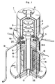
- 4 reference numeral 1 is a hydrogen peroxide vaporizing apparatus comprising an upper outer cylinder 2 and a lower outer cylinder 3.
- a flange 2A is provided in the lower surface of the upper outer cylinder 2 and a flange 3A is provided in the upper surface of the lower outer cylinder 3.
- a packing 4 is provided between the flanges.
- a ring 5 having concaved cross section is removably mounted to cover the flanges.
- An inlet port 6 is arranged on the upper portion of the upper outer cylinder 2.
- An inner cylinder 7 is provided inside the upper outer cylinder 2, which inner cylinder 7 has a flange 7A at the lower portion thereof and the periphery of the flange 7A is arranged to fit between a cutout portion 2B of the flange 2A and the inner periphery surface of the flange 3A.
- a hole 7B is provided in the flange 7A, with this, the carrier hot air is discharged to a vaporization chamber 8.
- the vaporization chamber 8 of hydrogen peroxide is determined by the flange 7A, an evaporation unit 12 and the lower outer cylinder 3.
- the profile of the vaporization chamber of the present invention is not limitted to the above construction.
- Shield disks 9 are provided in an upper inner tube 10 inside the inner cylinder 7 and a stairs construction is formed by the plural shield disks 9.
- Plural holes 9A are provided on the shield disks 9, which holes adjacent to each other are arranged staggeringly and the plural holes of the plural shield disks are arranged not to overlap each other to the vertical direction.
- the arrangement of the plural holes adjacent to each other and the arrangement of the holes of the plural shield disks are not limitted to the above described arrangement and any construction according to claim 1 in which the mix gas of the hydrogen peroxide gas and the carrier hot air can rise snakingly or swirlingly can be applied.
- the shield plate is not limitted to the disk-like shield.
- the drop splash removing apparatus is not limitted to the construction in which the plural shield plates provided with the plural holes are arranged to form stairs.
- the upper portion of the upper inner tube 10 opens to the upper inner surface of the inner cylinder 7 and a lower inner tube 11 is connected with the lower portion of the upper inner tube 10.
- the lower inner tube 11 passes through an inner path 12C of the evaporation unit 12C and an exhaust port 13 for the carrier hot air is provided in the lower portion of the lower inner tube 11.
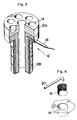
- the evaporation unit 12 is provided inside the lower outer cylinder 3, which evaporation unit 12 comprising an upper cylinder portion 12A and an lower cylinder portion 12B (Fig 3) having a diameter less than that of the upper cylinder portion and the inner path 12C is vertically provided in the inner side of the upper cylinder portion 12A and the lower cylinder portion 12B.
- Plural concaved cylindrical vaporization part 14 are provided on the upper surface of the cylindrical portion 12A.
- a cylindrical net 15 is provided about the surrounding of the concaved cylindrical vaporization part 14.
- the vaporization part 14 is not limitted to the concaved cylindrical unit, any dished unit can be applied.
- Plural heaters 16 are arranged to form stages in the lower cylinder portion 12B and lead wires 17 are connected with the heater 16.
- a space 22 is provided below the concaved cylindrical vaporization part 14 inside the evaporation unit 12 and a thermo sensor 18 is inserted to the upper portion thereof from the outside of the lower outer cylinder 3.
- thermo sensor 18 A vaporization condition can be measured by the thermo sensor 18 substantially equal to the condition of the concaved cylindrical vaporization part 14.
- the space 22 belonging to the upper cylinder portion 12A it can be filled with a filler having good coefficient of thermal conductivity and also it can be integrally molded with the same material as the evaporation unit 12.
- the space of the upper cylinder portion 12A is used only as a hole for the thermo sensor.
- heat insulating material 21 is filled.
- the hydrogen peroxide liquid is supplied from a quantitative apparatus (not shown ) through plural supply tubes 19.
- dropping nozzles 20 are connected with the end of the supply tube 19 and each dropping nozzle passes through the lower outer cylinder 3 and is turned down above the concaved cylindrical vaporization part 14.
- the operation of the disinfectant vaporizing apparatus according to the present invention is described based on Fig. 1 and 2.
- the pre-heated carrier gas at high temperature is applied to the disinfectant vaporizing apparatus from an inlet port 6.
- the heated carrier gas lowers along the interval between an upper outer cylinder 2 and an inner cylinder 7 to reach an evaporation chamber 8 through an opening 7B.
- disinfectant applied from a quantitative supply apparatus is dropped on a dished vaporization part from a dropping nozzle 20 through a supply tube 19.
- An evaporation unit 12 is heated by a heater means 16. Because the dished vaporization part is heated by heat transmitted through the outer or inner surface of the evaporation unit 12, the drop of the disinfectant dropped on the dished vaporization part is heated to evaporate.
- a cylindrical net 15 may be provided about the surrounding of the dished, for example concaved cylindrical evaporation part 14. With this, the drop is broken into parts by the cylindrical net 15, resulting in shorter evaporation time.
- Disinfection gas heated and vaporized on the dished evaporation part is carried to an opening of an upper inner tube 10 through a droplet splash removing apparatus, accompanied with the heated carrier gas.
- the droplet splash removing apparatus is provided with plural shield disks arranged to form stairs, said disks provided with plural holes, said holes adjacent to each other of said plural holes 9A of said shield disk 9 should be arranged staggeringly, additionally the plural holes provided on the plural shield disks 9 adjacent to each other should be arranged not to overlap each other to the vertical direction. Then the mix gas of the disinfection gas and the heated carrier gas rise snakingly or swirlingly. And the dropwise or splashwise disinfectant cannot rise therewith and combine each other into large drop, resulting in falling. Further since the mix gas of the disinfection gas and the heated carrier gas is snaked or swirled, the resulting mix gas has a uniform density.
- the mix gas of the disinfection gas and the heated carrier gas carried to the opening of the upper inner tube 10 from the drop splash removing apparatus descends through the upper inner tube 10 and the lower inner tube 11 to be supplied to the disinfection apparatus directly from an exhaust port 13 or through an induction pipe (not shown ).
Landscapes
- Chemical & Material Sciences (AREA)
- Chemical Kinetics & Catalysis (AREA)
- Health & Medical Sciences (AREA)
- General Chemical & Material Sciences (AREA)
- Epidemiology (AREA)
- Life Sciences & Earth Sciences (AREA)
- Animal Behavior & Ethology (AREA)
- General Health & Medical Sciences (AREA)
- Public Health (AREA)
- Veterinary Medicine (AREA)
- Apparatus For Disinfection Or Sterilisation (AREA)
- Feeding, Discharge, Calcimining, Fusing, And Gas-Generation Devices (AREA)
Claims (9)
- Générateur de gaz pour délivrer un désinfectant gazeux, comprenant:(a) une chambre de vaporisation (8) pour l'enrichissement d'un gaz porteur chauffé, par un désinfectant gazeux,(b) une unité de vaporisation (12) qui est alimentée par au moins un injecteur de gouttelettes (20) avec un liquide pouvant être vaporisé,caractérisé en ce que(c) l'unité de vaporisation (12) est pourvue, dans sa partie supérieure, d'une partie en forme de disque (12A), qui peut être chauffée,(d) sur la face supérieure de la partie en forme de disque (12A), une pluralité de cavités (14), dans lesquelles le liquide désinfectant est vaporisé, est disposée,(e) au-dessus de chaque cavité (14) au moins un injecteur de gouttelettes 20 est disposé, et(f) un dispositif en labyrinthe (9) disposé entre la partie en forme de disque (12A) et l'ouverture d'un tube interne (10), est prévu.
- Générateur de gaz selon la revendication 1,
caractérisé en ce que(a) au-dessus de la partie en forme de disque (12A) une enveloppe externe cylindrique (2), disposant d'une embouchure d'entrée (6) destinée au gaz porteur à son extrémité supérieure, et une enveloppe interne cylindrique (7) sont disposées, cette dernière dispose d'une extrémité supérieure fermée, d'une extrémité inférieure ouverte (7A) et est contenue dans ladite enveloppe externe de façon à ce qu'un espace (7C) soit créé entre les enveloppes externe et interne (2; 7),(b) ledit espace (7C) est relié à ladite embouchure d'entrée (6) et aux orifices (7A) adjacents auxdites cavités (14),(c) un tube interne allongé (10) est disposé à l'intérieur de ladite enveloppe interne (7) de façon à ce que l'extrémité supérieure dudit tube soit recouverte par l'enveloppe interne (7),et(d) le dispositif en labyrinthe (9) consiste en plaques perforées (9) qui sont disposées autour du tube interne (10) au-dessus des cavités (14) et à l'intérieur de l'enveloppe (7) afin de supprimer les gouttelettes de l'écoulement de gaz porteur de la chambre de vaporisation (8). - Générateur de gaz selon la revendication 2, caractérisé en ce que les plaques perforées (9) sont disposées en étages parallèles.
- Générateur de gaz selon l'une des revendications 2 et 3, caractérisé en ce que les perforations (9a) dans les plaques (9) sont disposées pour éviter un recouvrement vertical, en regardant d'une plaque (9) vers une autre.
- Générateur de gaz selon l'une des revendications 1 à 4, caractérisé en ce que les cavités (14) sont de forme cylindrique et supportent une grille cylindrique (15) recouvrant la surface de la paroi interne des cavités.
- Générateur de gaz selon l'une quelconque des revendications précédentes, caractérisé en ce que le tube interne (10) débouche sur la surface interne supérieure du cylindre interne (7) et en ce qu'il est en outre raccordé à l'embouchure d'évacuation (13) à travers le tube interne inférieur (11).
- Générateur de gaz selon l'une des revendications 1 à 6, caractérisé en ce que les moyens de chauffage (16) de l'unité de vaporisation (12) sont disposés au-dessous de la partie en forme de disque (12A), et en ce qu'une extrémité inférieure du tube interne (11) s'étend à travers lesdits moyens de chauffage (16).
- Générateur de gaz selon la revendication 7, caractérisé en ce que lesdits moyens de chauffage (16) présentent une partie inférieure allongée (12B) et en ce que ledit tube interne inférieur (11) s'étend à travers ladite partie inférieure allongée (12B).
- Générateur de gaz selon l'une des revendications précédentes, dans lequel un capteur thermo-sensible (18) est disposé dans la partie cylindrique supérieure (12A) de l'unité de vaporisation (12).
Applications Claiming Priority (2)
| Application Number | Priority Date | Filing Date | Title |
|---|---|---|---|
| JP326287/87 | 1987-12-23 | ||
| JP62326287A JPH0817804B2 (ja) | 1987-12-23 | 1987-12-23 | 殺菌剤気化装置 |
Publications (3)
| Publication Number | Publication Date |
|---|---|
| EP0321908A2 EP0321908A2 (fr) | 1989-06-28 |
| EP0321908A3 EP0321908A3 (en) | 1990-03-21 |
| EP0321908B1 true EP0321908B1 (fr) | 1994-03-30 |
Family
ID=18186082
Family Applications (1)
| Application Number | Title | Priority Date | Filing Date |
|---|---|---|---|
| EP88121238A Expired - Lifetime EP0321908B1 (fr) | 1987-12-23 | 1988-12-19 | Appareil pour la vaporisation de désinfectants |
Country Status (5)
| Country | Link |
|---|---|
| US (1) | US5078976A (fr) |
| EP (1) | EP0321908B1 (fr) |
| JP (1) | JPH0817804B2 (fr) |
| CA (1) | CA1313746C (fr) |
| DE (1) | DE3888809T2 (fr) |
Cited By (1)
| Publication number | Priority date | Publication date | Assignee | Title |
|---|---|---|---|---|
| US7090808B2 (en) | 2001-07-09 | 2006-08-15 | Pharmaceutical Systems, Inc. | Apparatus for testing sterilization methods and materials |
Families Citing this family (38)
| Publication number | Priority date | Publication date | Assignee | Title |
|---|---|---|---|---|
| JP2932072B2 (ja) * | 1989-02-22 | 1999-08-09 | 四国化工機株式会社 | 殺菌用過酸化水素ガス濃度調整装置 |
| US5258162A (en) * | 1989-11-07 | 1993-11-02 | Tetra Alfa Holdings S.A. | Method of producing a gaseous hydrogen peroxide-containing sterilization fluid |
| SE463240B (sv) * | 1989-11-07 | 1990-10-29 | Tetra Pak Holdings & Finance | Saett att framstaella gasformigt, vaeteperoxidinnehaallande steriliseringsfluidum |
| GB9022268D0 (en) * | 1990-10-13 | 1990-11-28 | Cmb Foodcan Plc | Sterilising apparatus |
| US5220637A (en) * | 1992-06-26 | 1993-06-15 | Aai Corporation | Method and apparatus for controllably generating smoke |
| US5666977A (en) * | 1993-06-10 | 1997-09-16 | Philip Morris Incorporated | Electrical smoking article using liquid tobacco flavor medium delivery system |
| US5553188A (en) * | 1995-02-24 | 1996-09-03 | Mks Instruments, Inc. | Vaporizer and liquid delivery system using same |
| US6094523A (en) * | 1995-06-07 | 2000-07-25 | American Sterilizer Company | Integral flash steam generator |
| DE19704639C2 (de) * | 1997-02-07 | 2000-11-02 | Tetra Laval Holdings & Finance | Verfahren zum Verdampfen und Überhitzen eines Sterilisierungsmittels und Vorrichtung hierfür |
| JP3707035B2 (ja) * | 1997-04-22 | 2005-10-19 | 株式会社イシン技研 | 竪形蒸発缶 |
| US6106772A (en) * | 1997-06-23 | 2000-08-22 | Ethicon, Inc. | Injector impinger |
| JP2001004095A (ja) * | 1999-06-18 | 2001-01-09 | Nippon M K S Kk | 気化器 |
| US6948491B2 (en) * | 2001-03-20 | 2005-09-27 | Aerogen, Inc. | Convertible fluid feed system with comformable reservoir and methods |
| SE516643C2 (sv) * | 2000-05-31 | 2002-02-05 | Tetra Laval Holdings & Finance | Förfarande och anordning för framställning av ett gasformigt medium |
| US6477890B1 (en) | 2000-09-15 | 2002-11-12 | K-Line Industries, Inc. | Smoke-producing apparatus for detecting leaks |
| US20020098111A1 (en) * | 2000-12-04 | 2002-07-25 | Nguyen Nick N. | Vaporizer |
| US6746652B2 (en) | 2001-07-09 | 2004-06-08 | Pharmaceutical Systems, Inc. | Production of hydrogen peroxide vapor-air mixtures |
| DE10145818C1 (de) * | 2001-09-17 | 2002-10-10 | Alfill Engineering Gmbh & Co K | Sterilisiervorrichtung mit H202-Verdampfer |
| US7300038B2 (en) * | 2002-07-23 | 2007-11-27 | Advanced Technology Materials, Inc. | Method and apparatus to help promote contact of gas with vaporized material |
| US6921062B2 (en) * | 2002-07-23 | 2005-07-26 | Advanced Technology Materials, Inc. | Vaporizer delivery ampoule |
| US6909839B2 (en) * | 2003-07-23 | 2005-06-21 | Advanced Technology Materials, Inc. | Delivery systems for efficient vaporization of precursor source material |
| CN101495190B (zh) * | 2005-03-16 | 2013-05-01 | 高级技术材料公司 | 用于从固体源递送试剂的系统 |
| CN102060268A (zh) * | 2005-03-29 | 2011-05-18 | 卡西欧计算机株式会社 | 蒸发装置以及液体吸收件 |
| US7713473B2 (en) * | 2005-06-30 | 2010-05-11 | Ethicon, Inc. | Sterilization system and vaporizer therefor |
| DE102005030822A1 (de) * | 2005-07-01 | 2007-01-11 | Krones Ag | Verfahren und Vorrichtung zum Überwachen eines Verdampfers |
| US20080241805A1 (en) | 2006-08-31 | 2008-10-02 | Q-Track Corporation | System and method for simulated dosimetry using a real time locating system |
| DE102007034205A1 (de) * | 2007-07-23 | 2009-01-29 | Krones Ag | Verdampfer zum Sterilisieren von Kunststoffbehältern |
| US8297223B2 (en) * | 2007-10-02 | 2012-10-30 | Msp Corporation | Method and apparatus for particle filtration and enhancing tool performance in film deposition |
| JP4922271B2 (ja) * | 2008-09-19 | 2012-04-25 | 株式会社大気社 | 空調対象空間の燻蒸方法 |
| FR2952540B1 (fr) * | 2009-11-13 | 2012-04-20 | Jce Biotechnology | Dispositif de decontamination de surfaces par du peroxyde d'hydrogene gazeux adapte pour etre monte sur une enceinte de manipulation et enceinte de manipulation ainsi equipee |
| JP5604511B2 (ja) * | 2010-03-31 | 2014-10-08 | パナソニックヘルスケア株式会社 | 過酸化水素ガス生成装置 |
| KR20200124780A (ko) | 2012-05-31 | 2020-11-03 | 엔테그리스, 아이엔씨. | 배취식 침착을 위한 고 물질 플럭스를 갖는 유체의 소스 시약-기반 수송 |
| EP3108902B1 (fr) * | 2015-06-24 | 2018-07-18 | Gea Procomac S.p.A. | Procédée pour stériliser des récipients |
| PH12019500361B1 (en) | 2016-09-27 | 2023-03-24 | Orihiro Eng Co Ltd | Aseptic filling and packaging apparatus, and method of aseptically filling plastic film package bag with material |
| GB202007453D0 (en) * | 2020-05-19 | 2020-07-01 | Aseptick Ltd | Apparatus and methods for decontaminating enclosed spaces |
| KR102519832B1 (ko) * | 2020-12-31 | 2023-04-11 | 주식회사 우정바이오 | 과산화수소 증기 기화기 |
| DE102024113747A1 (de) * | 2024-05-16 | 2025-11-20 | Gasti Verpackungsmaschinen Gmbh | Vorrichtung zum verdampfen einer flüssigkeit |
| DE102024113746A1 (de) * | 2024-05-16 | 2025-11-20 | Gasti Verpackungsmaschinen Gmbh | Vorrichtung zum verdampfen einer flüssigkeit |
Family Cites Families (12)
| Publication number | Priority date | Publication date | Assignee | Title |
|---|---|---|---|---|
| US604598A (en) * | 1898-05-24 | Vacuum | ||
| US468048A (en) * | 1892-02-02 | Thomas james ratnee | ||
| US1410164A (en) * | 1921-04-26 | 1922-03-21 | Owen L Carroll | Heating apparatus for vapor-bath devices |
| FR708729A (fr) * | 1930-04-09 | 1931-07-28 | Appareil pour volatiliser par la vapeur des substances pharmaceutiques balsamiques ou autres, pour les mélanger avec la vapeur et pour les surchauffer en vue de leur utilisation dans des installations de bains de vapeur, de désinfection, ou autres | |
| GB392044A (en) * | 1932-09-15 | 1933-05-11 | Manuf De Machines Auxiliaires | Means permitting of evaporating or of de-gasifying in vacuo continuously a liquid contained in any vessel or apparatus |
| US2047973A (en) * | 1935-06-04 | 1936-07-21 | Harold P Lawton | Apparatus for treating leather |
| US2262327A (en) * | 1939-09-26 | 1941-11-11 | Dougald T Mckinnon | Humidor |
| US4003967A (en) * | 1974-10-31 | 1977-01-18 | Les Placement Courteau Limitee | Electric heating and humidifying apparatus |
| US4190052A (en) * | 1978-12-18 | 1980-02-26 | The Gillette Company | Steam facial apparatus |
| DE3235476C2 (de) * | 1981-11-14 | 1986-09-11 | Jagenberg AG, 4000 Düsseldorf | Verfahren und Einrichtung zum Entkeimen von Verpackungsmaterial, insbesondere von Verpackungsbehältern |
| SE8300356L (sv) * | 1983-01-25 | 1984-07-26 | Tetra Pak Int | Sett och anordning for forangning av en vetska |
| IN162484B (fr) * | 1983-10-03 | 1988-06-04 | Pall Corp |
-
1987
- 1987-12-23 JP JP62326287A patent/JPH0817804B2/ja not_active Expired - Lifetime
-
1988
- 1988-12-16 US US07/285,267 patent/US5078976A/en not_active Expired - Fee Related
- 1988-12-19 EP EP88121238A patent/EP0321908B1/fr not_active Expired - Lifetime
- 1988-12-19 DE DE3888809T patent/DE3888809T2/de not_active Expired - Fee Related
- 1988-12-21 CA CA000586664A patent/CA1313746C/fr not_active Expired - Fee Related
Cited By (1)
| Publication number | Priority date | Publication date | Assignee | Title |
|---|---|---|---|---|
| US7090808B2 (en) | 2001-07-09 | 2006-08-15 | Pharmaceutical Systems, Inc. | Apparatus for testing sterilization methods and materials |
Also Published As
| Publication number | Publication date |
|---|---|
| JPH01166758A (ja) | 1989-06-30 |
| EP0321908A2 (fr) | 1989-06-28 |
| CA1313746C (fr) | 1993-02-23 |
| DE3888809D1 (de) | 1994-05-05 |
| JPH0817804B2 (ja) | 1996-02-28 |
| DE3888809T2 (de) | 1994-08-11 |
| US5078976A (en) | 1992-01-07 |
| EP0321908A3 (en) | 1990-03-21 |
Similar Documents
| Publication | Publication Date | Title |
|---|---|---|
| EP0321908B1 (fr) | Appareil pour la vaporisation de désinfectants | |
| EP2038597B1 (fr) | Appareil et procédé de séchage d'instruments au moyen de vapeur d'eau surchauffée | |
| CA1296996C (fr) | Evaporateur a colonnes paralleles garnies | |
| US5826647A (en) | Heat exchanger | |
| US4028445A (en) | Apparatus for wetting respiratory gas | |
| US6521047B1 (en) | Process and apparatus for liquid delivery into a chemical vapor deposition chamber | |
| JPS5811625A (ja) | 槽形容器の殺菌方法および装置 | |
| US4375185A (en) | Milk sterilizing apparatus | |
| JP7204487B2 (ja) | 充填製品充填プラントにおいて流体媒体を気化させるための装置 | |
| US6251341B1 (en) | Method for treatment of fluent products | |
| US6161300A (en) | Alcohol vapor dryer system | |
| US2713895A (en) | Apparatus for supplying and distributing liquids | |
| CN1365296A (zh) | 一种对液态产品进行蒸发冷却的装置 | |
| US3326202A (en) | Atmospheric type water heating apparatus | |
| JP2729417B2 (ja) | 減圧気化冷却装置 | |
| JP3862821B2 (ja) | 熱交換器 | |
| US2743350A (en) | Electric vaporizer | |
| US4026686A (en) | Vacuum filter for the purification of gaseous materials | |
| JPH0934559A (ja) | 蒸気加熱装置 | |
| JPH0934558A (ja) | 蒸気加熱装置 | |
| WO2026015501A1 (fr) | Appareil de lyophilisation et procédé de lyophilisation associé | |
| SU844014A1 (ru) | Пленочный вакуумный испаритель | |
| JP2023540583A (ja) | 液体および/またはエアロゾルを気化するための気化器装置、特に滅菌気化器装置 | |
| HK1130886B (en) | Apparatus and method for drying instruments using superheated steam |
Legal Events
| Date | Code | Title | Description |
|---|---|---|---|
| PUAI | Public reference made under article 153(3) epc to a published international application that has entered the european phase |
Free format text: ORIGINAL CODE: 0009012 |
|
| AK | Designated contracting states |
Kind code of ref document: A2 Designated state(s): DE FR GB |
|
| PUAL | Search report despatched |
Free format text: ORIGINAL CODE: 0009013 |
|
| AK | Designated contracting states |
Kind code of ref document: A3 Designated state(s): DE FR GB |
|
| 17P | Request for examination filed |
Effective date: 19900419 |
|
| RIN1 | Information on inventor provided before grant (corrected) |
Inventor name: TANAKA, TATSUO Inventor name: HATANAKA, KOICHI Inventor name: SHIBAUCHI YOSHITO |
|
| 17Q | First examination report despatched |
Effective date: 19910618 |
|
| GRAA | (expected) grant |
Free format text: ORIGINAL CODE: 0009210 |
|
| AK | Designated contracting states |
Kind code of ref document: B1 Designated state(s): DE FR GB |
|
| REF | Corresponds to: |
Ref document number: 3888809 Country of ref document: DE Date of ref document: 19940505 |
|
| ET | Fr: translation filed | ||
| PLBE | No opposition filed within time limit |
Free format text: ORIGINAL CODE: 0009261 |
|
| STAA | Information on the status of an ep patent application or granted ep patent |
Free format text: STATUS: NO OPPOSITION FILED WITHIN TIME LIMIT |
|
| 26N | No opposition filed | ||
| PGFP | Annual fee paid to national office [announced via postgrant information from national office to epo] |
Ref country code: DE Payment date: 20011129 Year of fee payment: 14 |
|
| PGFP | Annual fee paid to national office [announced via postgrant information from national office to epo] |
Ref country code: GB Payment date: 20011214 Year of fee payment: 14 |
|
| PGFP | Annual fee paid to national office [announced via postgrant information from national office to epo] |
Ref country code: FR Payment date: 20011218 Year of fee payment: 14 |
|
| REG | Reference to a national code |
Ref country code: GB Ref legal event code: IF02 |
|
| PG25 | Lapsed in a contracting state [announced via postgrant information from national office to epo] |
Ref country code: GB Free format text: LAPSE BECAUSE OF NON-PAYMENT OF DUE FEES Effective date: 20021219 |
|
| PG25 | Lapsed in a contracting state [announced via postgrant information from national office to epo] |
Ref country code: DE Free format text: LAPSE BECAUSE OF NON-PAYMENT OF DUE FEES Effective date: 20030701 |
|
| GBPC | Gb: european patent ceased through non-payment of renewal fee |
Effective date: 20021219 |
|
| PG25 | Lapsed in a contracting state [announced via postgrant information from national office to epo] |
Ref country code: FR Free format text: LAPSE BECAUSE OF NON-PAYMENT OF DUE FEES Effective date: 20030901 |
|
| REG | Reference to a national code |
Ref country code: FR Ref legal event code: ST |