EP0321079B1 - Adaptive control system for operating adjustable automotive suspension units - Google Patents
Adaptive control system for operating adjustable automotive suspension units Download PDFInfo
- Publication number
- EP0321079B1 EP0321079B1 EP88310072A EP88310072A EP0321079B1 EP 0321079 B1 EP0321079 B1 EP 0321079B1 EP 88310072 A EP88310072 A EP 88310072A EP 88310072 A EP88310072 A EP 88310072A EP 0321079 B1 EP0321079 B1 EP 0321079B1
- Authority
- EP
- European Patent Office
- Prior art keywords
- suspension units
- units
- suspension
- operating
- control system
- Prior art date
- Legal status (The legal status is an assumption and is not a legal conclusion. Google has not performed a legal analysis and makes no representation as to the accuracy of the status listed.)
- Expired - Lifetime
Links
Images

Classifications
-
- B—PERFORMING OPERATIONS; TRANSPORTING
- B60—VEHICLES IN GENERAL
- B60G—VEHICLE SUSPENSION ARRANGEMENTS
- B60G17/00—Resilient suspensions having means for adjusting the spring or vibration-damper characteristics, for regulating the distance between a supporting surface and a sprung part of vehicle or for locking suspension during use to meet varying vehicular or surface conditions, e.g. due to speed or load
- B60G17/015—Resilient suspensions having means for adjusting the spring or vibration-damper characteristics, for regulating the distance between a supporting surface and a sprung part of vehicle or for locking suspension during use to meet varying vehicular or surface conditions, e.g. due to speed or load the regulating means comprising electric or electronic elements
- B60G17/018—Resilient suspensions having means for adjusting the spring or vibration-damper characteristics, for regulating the distance between a supporting surface and a sprung part of vehicle or for locking suspension during use to meet varying vehicular or surface conditions, e.g. due to speed or load the regulating means comprising electric or electronic elements characterised by the use of a specific signal treatment or control method
- B60G17/0185—Resilient suspensions having means for adjusting the spring or vibration-damper characteristics, for regulating the distance between a supporting surface and a sprung part of vehicle or for locking suspension during use to meet varying vehicular or surface conditions, e.g. due to speed or load the regulating means comprising electric or electronic elements characterised by the use of a specific signal treatment or control method for failure detection
-
- B—PERFORMING OPERATIONS; TRANSPORTING
- B60—VEHICLES IN GENERAL
- B60G—VEHICLE SUSPENSION ARRANGEMENTS
- B60G2400/00—Indexing codes relating to detected, measured or calculated conditions or factors
- B60G2400/10—Acceleration; Deceleration
- B60G2400/106—Acceleration; Deceleration longitudinal with regard to vehicle, e.g. braking
-
- B—PERFORMING OPERATIONS; TRANSPORTING
- B60—VEHICLES IN GENERAL
- B60G—VEHICLE SUSPENSION ARRANGEMENTS
- B60G2400/00—Indexing codes relating to detected, measured or calculated conditions or factors
- B60G2400/20—Speed
- B60G2400/204—Vehicle speed
-
- B—PERFORMING OPERATIONS; TRANSPORTING
- B60—VEHICLES IN GENERAL
- B60G—VEHICLE SUSPENSION ARRANGEMENTS
- B60G2400/00—Indexing codes relating to detected, measured or calculated conditions or factors
- B60G2400/25—Stroke; Height; Displacement
- B60G2400/252—Stroke; Height; Displacement vertical
-
- B—PERFORMING OPERATIONS; TRANSPORTING
- B60—VEHICLES IN GENERAL
- B60G—VEHICLE SUSPENSION ARRANGEMENTS
- B60G2400/00—Indexing codes relating to detected, measured or calculated conditions or factors
- B60G2400/40—Steering conditions
-
- B—PERFORMING OPERATIONS; TRANSPORTING
- B60—VEHICLES IN GENERAL
- B60G—VEHICLE SUSPENSION ARRANGEMENTS
- B60G2500/00—Indexing codes relating to the regulated action or device
- B60G2500/10—Damping action or damper
- B60G2500/102—Damping action or damper stepwise
-
- B—PERFORMING OPERATIONS; TRANSPORTING
- B60—VEHICLES IN GENERAL
- B60G—VEHICLE SUSPENSION ARRANGEMENTS
- B60G2500/00—Indexing codes relating to the regulated action or device
- B60G2500/20—Spring action or springs
- B60G2500/22—Spring constant
-
- B—PERFORMING OPERATIONS; TRANSPORTING
- B60—VEHICLES IN GENERAL
- B60G—VEHICLE SUSPENSION ARRANGEMENTS
- B60G2600/00—Indexing codes relating to particular elements, systems or processes used on suspension systems or suspension control systems
- B60G2600/04—Means for informing, instructing or displaying
- B60G2600/044—Alarm means
-
- B—PERFORMING OPERATIONS; TRANSPORTING
- B60—VEHICLES IN GENERAL
- B60G—VEHICLE SUSPENSION ARRANGEMENTS
- B60G2600/00—Indexing codes relating to particular elements, systems or processes used on suspension systems or suspension control systems
- B60G2600/20—Manual control or setting means
-
- B—PERFORMING OPERATIONS; TRANSPORTING
- B60—VEHICLES IN GENERAL
- B60G—VEHICLE SUSPENSION ARRANGEMENTS
- B60G2600/00—Indexing codes relating to particular elements, systems or processes used on suspension systems or suspension control systems
- B60G2600/70—Computer memory; Data storage, e.g. maps for adaptive control
Definitions
- This invention relates to a control system, for operating adjustable automotive suspension units, which has the ability to adapt to impairment of the adjustable feature of the suspension units.
- Multistable automotive suspension units have been known for some time. Such suspension units are typically mounted between the sprung and unsprung portions of the vehicle. Suspension units defined as “multistable” have the ability to be operated in a plurality of predetermined states. Such suspension units are intended to provide control of vehicle ride and handling which may be tailored to particular road surfaces and/or driver characteristics. In typical fashion, the particular state chosen for the multistable unit is determined by a control algorithm with inputs from a variety of vehicle parameters. For example, it is known to control a multistable suspension unit by utilizing vehicle linear acceleration, braking, steering activity, and vehicle speed as well as through a manually operable mode switch.
- U.S. Patent 4,621,833 discloses a system for operating multistable suspension units, including feedback of the operating mode of each suspension unit.
- U.S. Patent 4.700,303 discloses a system for operating a vehicle height adjusting apparatus in the event that an abnormality is detected in the sensors which measure the vehicle s ride height. If such abnormality is detected, the control system will operate a compressor until a minimum pressure is produced in an air suspension system. Similarly, it is known to compensate for loss of the ability to control one or more of the suspension units in an automotive vehicle by placing all of the units into a predetermined control position.
- U.S. Patents 4,526,401 and 4,666,180 disclose two control systems in which the inability to operate adjustable suspension units is compensated for by the placement of all the operational suspension units into a "normal" damping force condition.
- control schemes set forth in the '303, '401 and '180 patents are not adaptive inasmuch as they lack the capability of selecting an operating mode for any viable suspension units which operating mode takes into account the specific nature of the inability to adjust one or more of the remaining suspension units. Too, such systems do not provide for the contingency that the "normal" adjustment position may not be attainable.
- a control system according to this invention will minimise the degradation of the ride control of a vehicle in the event that one of more of the adjustable suspension units becomes inoperative.
- DE-A-3437 799 discloses a control system for adjustable suspension units of an automotive vehicle corresponding to the preamble of claim 1.
- a control system for governing a plurality of multiple operating mode adjustable suspension units in an automotive vehicle, comprising; adjustment means for receiving and adjustment control signal and for placing said suspension units in any of said multiple adjustment modes; fault warning means for detecting an inablility of said adjustment means to adjust one or more of said suspension units and for generating a fault warning signal in response to said detection; characterised in that the system further comprises diagnostic means responsive to said fault warning signal and operatively connected with said adjustment means for determining the extent to which the ability to adjust said units has been impaired by commanding said adjustment means to sequentially place said units into at least two of said multiple operating modes and by observing the response of said suspension unit to said commands; and mode selection means, operatively connected with said diagnostic means, for deciding into which of said multiple operating modes said suspension units should be directed, by comparing the results of said sequential operation of said suspension units by said diagnostic means to a ranked order of states of impairment of said suspension units and by selecting that attainable operation mode which is most preferable according to said ranked order, said mode selection
- a method for governing a plurality of multiple operating mode adjustable suspension units in an automotive vehicle comprising the steps of, detecting a loss of control of the adjustability of one or more of said suspension units, attempting to place said suspension units in an authorised operating position upon detection of such loss of control, detecting the resulting operating position of the suspension units, and inhibiting the control system from making any further changes in the operating positions of the suspension units in the event that the suspension units have moved to said authorised operating position, characterised by taking the following additional steps in the event that said suspension units have not assumed such authorised operating position, determining the extent to which the ability to adjust said suspension units has been impaired, by commanding to sequentially place said unit into at least two of said multiple operating mode and by observing the response of said units to said commands, comparing the result of said sequential operation of the suspension unit to a ranked order of states of impairment of the suspension unit, selecting an operating position for the suspension units, which is most preferred according to said ranked order and directing the suspension units into the selected operating position.
- a control system according to the present invention is intended for use with adjustable suspension units typically found in automotive vehicles.
- U. S. Patents 4,313,529; 4,621,833 and 4,666,180 which are hereby incorporated by reference, disclose adjustable suspension units which are exemplary of but a portion of the class of suspension units which may be controlled by a system according to the present invention.
- the motor vehicle in Figure 1 is equipped in conventional fashion with adjustable air spring suspension units 12, which serve to control the vertical motion of wheel and tire assemblies 10.
- the air springs are supplied with compressed air by compressor 21, which is electrically powered by the vehicle's battery.
- Each of adjustable suspension units 12 is operatively connected with and controlled by suspension control module 14.
- the control module includes a micropressor and may be arranged according to a number of different architectures. Those skilled in the art will appreciate in view of this disclosure that each such architecture could generally include an input-output control circuit (I/O) for exchanging data with external devices and a random access memory (RAM) for temporarily holding data while the data are being processed. Control programs including unit commands will be sequentially read from a read-only memory (ROM). Unit commands will be executed by a central processing unit (CPU).
- I/O input-output control circuit
- RAM random access memory
- FIG. 1 represents merely one preferred embodiment of the present invention, it being understood that this invention is suitable for use with other suspension units such as air/hydraulic or hydraulic load bearing units or combination adjustable load bearing and adjustable damping units such as those known in the art.
- a system according to this invention could be employed in conjunction with the control of damping, or spring rate, or both functions.
- This system could also be employed in conjunction with adjustable suspension units having variable ride height or spring load control characteristics.
- the present invention could be applied preferentially to the suspension units located at only one end of the vehicle such as the front or rear.
- a system according to the present invention is operated by the suspension control module 14 which receives inputs from each of the suspension units as well as inputs from various vehicle sensors.
- the vehicle sensors could include a steering sensor, brake sensor, speed sensor, suspension ride height sensor, manual mode selection switch or other types of sensing devices.
- a system according to the present invention could be employed in connection with a simple multi-positionable manual suspension control device, such as a switching device for placing adjustable suspension units into either of two selectable positions.
- the purpose of each of the sensing devices is to help the control unit to decide which of the multiple operating modes the suspension units should be placed into during the normal operation of the system.
- a system according to the present invention is intended to make decisions regarding what operating positions the various suspension units should be placed into in the event that the system has lost the full ability to properly control each of the individual suspension units.
- This inability of the adjustment means to adjust one or more of the suspension units could result from a variety of sources such as broken power supply conductors affecting individual suspension units, incorrectly wired signal conductors causing erroneous adjustments, or yet other sources.
- sources such as broken power supply conductors affecting individual suspension units, incorrectly wired signal conductors causing erroneous adjustments, or yet other sources.
- one type of inability of the adjustment means to properly adjust the unit would occur were the control wiring to be transposed such that a "firm" adjustment command signal is met with a "normal” adjustment.
- suspension control module 14 receives input data from vehicle sensors 16 and adjustable suspension units 12.
- the information received from these adjustable suspension units by the suspension control module comprises a feedback signal indicating the position of the suspension unit.
- Devices for providing such position feedback are disclosed in U.S. Patents 4,526,401, and 4,621,833.
- position feedback devices may be viewed as multi-position switches which track the actual positions of the individual suspension units, so that the actual positions may be compared with the ordered positions, with any discrepancy being recorded in a register within the suspension system control module.
- the control module's computer decides when the adjustable suspension units should be moved from the normal to the firm position and vice versa. This mode selection may be accomplished through a variety of adjustment means.
- U.S. Patent 4,621,833 discloses such a means in which a multi-positionable electromagnetic motor causes a control valve within the shock absorber to move to one of two operating positions. The computer will then record, in a suitable register, the movement of the suspension unit into the directed operating position. If, however, the suspension unit does not move into the designated position, the computer will note such failure and generate a fault warning signal. This could be accomplished by feeding the output of a multi-positionable switch, such as that illustrated in U.S.
- Patent 4,621,833 to the diagnostic and mode selection portions of the present system. Because the multi-positionable switch tracks the actual position of the suspension unit's adjuster, the diagnostic means may use the position information to determine the extent of the system's impairment by comparing a commanded position to the actual position of the suspension unit. Similarly, the mode selection means will utilize position feedback to keep track of the actual position of each of the suspension units.
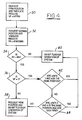
- the computer Upon generating a fault warning signal, the computer will determine the extent to which the ability to adjust the suspension units has been impaired. This diagnostic process may be accomplished by commanding the suspension unit adjustment means to sequentially place the suspension units into at least two multiple operating modes and by observing the responses of the suspension units to such commands. These processes are shown in blocks 30 and 32 of Figure 4.
- the computer's CPU reads an instruction from the ROM and commands the adjustment means to place the adjustable suspension units into the firm position or firm operating mode. After this command has been given, the computer tabulates the number of suspension units in the firm position. If the last command to the suspension units prior to generation of the fault warning signal was the "firm" command, however, such command need not be duplicated. Having made the first tabulation, the computer moves to block 32 wherein the adjustment means is commanded to place the units into the normal operating position. As before, the computer tabulates or counts the number of units which have actually moved into the normal operating position. The computer then moves on with the balance of the algorithm which implements the ranking system shown in Figure 5.
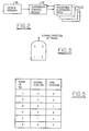
- Figure 5 illustrates a ranked order of six possible states of impairment for four adjustable suspension units.
- the columns labeled "Normal Position” and "Firm Position” contain entries corresponding to the numbers of suspension units (out of a total of four) capable of being placed into the indicated operating position, whether normal or firm.
- State No. 1 is the most desirable state with state No. 6 being the least desirable.
- State No. 1 indicates that it is most desirable in the event that the fault warning means has detected an inability of the adjustment means to adjust one or more of the suspension units that the system be operated if possible such that all four of the suspension units are placed into the normal position.
- the shock absorbers are in the firm position.
- state 4 also stands for the condition wherein two of the shock absorbers at the front of the vehicle are firm whereas two at the rear are in the normal position.
- state 6 on the other hand, it is assumed that both of the shock absorbers at the rear of the vehicle are in the firm position whereas two in the front are in the normal position, or alternatively it is assumed that, for example, the left front and right rear are in the normal position, whereas the right front and left rear shock absorbers are in the firm position.
- state 5 it is assumed that in the event it is possible to place three shock absorbers in the firm position but only one in the normal position, such a position is preferable to the state shown as state No. 6 and, therefore, this state will be selected.
- the ranked order of Figure 5 is implemented for a two-position shock absorber system by the logic algorithm contained in Figure 4.
- This algorithm is for a system in which the mode selection means comprising the microprocessor, multi-positionable electromagnetic motors, and interconnecting electronic devices, selects a single operating mode for all of the suspension units based upon the results of the operation of a diagnostic means as well as the results of a comparison of the such results with the ranked order of Figure 5.
- Other algorithms could be employed according to the present invention to provide individual control for each of the suspension units, based upon the results of the diagnostic routine and a subsequent comparison with a suitable ranked order scheme.
- the microprocessor tracks the position of each suspension unit individually, it will know if any of the suspension units have been wired incorrectly such that control commands are inverted with the result that a "firm" adjustment command is met with a "normal” adjustment, and vice-versa. If such is the case, the microprocessor will know that it is possible to operate the defective suspension units by giving such units an adjustment command which is nominally opposite to the desired command.
- the computer asks the question whether more shock absorbers are capable of being shifted to the firm position or more to the normal position. If the answer is no, in other words, if more shock absorbers are capable of being placed into the normal position than the number capable of being placed into the firm position, the computer will transfer to block 40 wherein further operation of the system will be inhibited. Accordingly, at block 40 the suspension units will be maintained in the position which they occupied when the computer requested at block 32 be placed in the normal position.
- the computer transfers to block 36 wherein the number capable of being placed in the firm position is compared with the number three. If the number of shock absorbers capable of being placed in the firm position is not equal to three, logic dictates that the number being capable of being placed in the firm position must be equal to four because from block 34 it is already known that the number of firm shock absorbers exceeds the number of normal shock absorbers. Having answered the question of block 36 in the negative, the algorithm transfers to block 38 wherein the firm position is requested and further operation of the system is inhibited.
- the logic embodied in blocks 42 and 44 prevents state 6 of Figure 5 from prevailing.
- block 42 if units 1 and 4 are in the same position, it is known that units 1 and 2 cannot be in the firm position while units 3 and 4 are occupying the normal position. It is also known that units 1 and 3 cannot be in the normal position while units 4 and 2 are occupying the firm position. If the answer to the question at block 42 is "no" and the computer transfers to block 44, and the answers to the questions in block 44 are "yes", it will be known that state 6 has been avoided because suspension units 3 and 4 are in the firm position and as a result, neither of the conditions in state 6 are possible.
- the embodiment described herein in which the mode selection means implements a ranked order through the use of a logic algorithm contained in a software program comprises but one means for executing a comparison of the results of a sequential operation of suspension units by a diagnostic means to a ranked order. Comparison of the results of the operation of suspension units by a diagnostic means to a ranked order of states of impairment could also be accomplished by recording the individual operating characteristics of each suspension unit and by using the recorded results in conjunction with a lookup table contained within the computer's ROM so as to select an operating mode for each of the suspension units.
- mode selection means could be employed for selecting not only a single operating mode for all the suspension units but, alternatively, an individual operating mode could be selected for each of the units based upon the results of the diagnostic operation and a comparison of those results with the ranked order.
- a system may operate with the following steps. First, in order to trigger operation of the system, the system will detect a loss of control of the adjustability of one or more of the suspension units. This detection will be answered with an attempt to place the suspension units in an authorized operating position. After such attempt, the resulting operating positions of the suspension units will be noted and the system will be inhibited from making further changes in the positions of the suspension units in the event that the suspension units have moved to the authorized operating position. If, however, the suspension units have not moved to the authorized operating position the system will then determine the extent to which the ability to adjust the suspension units has been impaired and will then select an operating position for the suspension units based upon the determination of the extent of adjustment impairment.
- the authorized operating position described herein may comprise the position which the suspension units occupied at a time immediately preceding the detection of the loss of control of adjustability or, alternatively, the authorized operating position may comprise a normal operating position which allows the suspension units to provide acceptable ride control characteristics.
- a system according to the present invention could further comprise standard operating means for receiving vehicular operating data and means for using such data as well as recorded suspension unit responses for deciding into which of the multiple operating modes the suspension units should be directed.
- the standard operating means could be structured according to the lines of the system disclosed in U.S. Patent 4,621,833 and in general could include a logic algorithm comprising a logical "OR" strategy such that the suspension units are ordered to an adjusted position whenever one or more of a plurality of control conditions has been satisfied.
- the multistable suspension units of the '833 patent are ordered to the firm position whenever one of several individual vehicular inputs is present.
- a system according to the present invention detects an abnormal condition in terms of the inability to adjust one or more suspension units, the standard operating portion of the system could continue to operate the system in the attainable operating modes according to the normal operating procedure, including, for example, the previously described logic algorithm. Accordingly, a system according to this invention need not inhibit completely the operation of the adjustable suspension units as specified in block 40 of Fiqure 4.
Landscapes
- Engineering & Computer Science (AREA)
- Mechanical Engineering (AREA)
- Vehicle Body Suspensions (AREA)
Applications Claiming Priority (2)
| Application Number | Priority Date | Filing Date | Title |
|---|---|---|---|
| US133985 | 1987-12-16 | ||
| US07/133,985 US4805923A (en) | 1987-12-16 | 1987-12-16 | Adaptive control system for operating adjustable automotive suspension units |
Publications (3)
| Publication Number | Publication Date |
|---|---|
| EP0321079A2 EP0321079A2 (en) | 1989-06-21 |
| EP0321079A3 EP0321079A3 (en) | 1990-05-30 |
| EP0321079B1 true EP0321079B1 (en) | 1993-07-07 |
Family
ID=22461232
Family Applications (1)
| Application Number | Title | Priority Date | Filing Date |
|---|---|---|---|
| EP88310072A Expired - Lifetime EP0321079B1 (en) | 1987-12-16 | 1988-10-26 | Adaptive control system for operating adjustable automotive suspension units |
Country Status (5)
| Country | Link |
|---|---|
| US (1) | US4805923A (ja) |
| EP (1) | EP0321079B1 (ja) |
| JP (1) | JP2889579B2 (ja) |
| CA (1) | CA1314960C (ja) |
| DE (1) | DE3882212T2 (ja) |
Families Citing this family (27)
| Publication number | Priority date | Publication date | Assignee | Title |
|---|---|---|---|---|
| US5263737A (en) * | 1988-08-29 | 1993-11-23 | Honda Giken Kabushiki Kaisha | Device for stabilizing the attitude of an automobile |
| JPH082724B2 (ja) * | 1988-12-20 | 1996-01-17 | マツダ株式会社 | 車両のサスペンション装置 |
| JP2745416B2 (ja) * | 1989-01-19 | 1998-04-28 | 富士重工業株式会社 | 車高調整装置付車両の車高制御方法 |
| US4960291A (en) * | 1989-06-06 | 1990-10-02 | Lin Chien Hung | Automotive suspension system |
| US4969662A (en) * | 1989-06-08 | 1990-11-13 | Aura Systems, Inc. | Active damping system for an automobile suspension |
| DE3919040A1 (de) * | 1989-06-10 | 1990-12-13 | Porsche Ag | Verfahren und vorrichtung zur justierung einer hoehenstands-regelanlage eines fahrzeugs |
| US5120982A (en) * | 1989-11-14 | 1992-06-09 | Ford Motor Company | Fault correcting circuit |
| US5243324A (en) * | 1991-11-07 | 1993-09-07 | Ford Motor Company | Method of detecting a fault in an automotive system |
| GB9409929D0 (en) * | 1994-05-18 | 1994-07-06 | Acg France | Warning circuit for levelling control system |
| US9327726B2 (en) | 2004-10-05 | 2016-05-03 | Vision Works Ip Corporation | Absolute acceleration sensor for use within moving vehicles |
| US9878693B2 (en) | 2004-10-05 | 2018-01-30 | Vision Works Ip Corporation | Absolute acceleration sensor for use within moving vehicles |
| US7287760B1 (en) * | 2006-08-21 | 2007-10-30 | Bfs Diversified Products, Llc | Vehicle suspension system and method |
| US8285447B2 (en) * | 2007-03-20 | 2012-10-09 | Enpulz, L.L.C. | Look ahead vehicle suspension system |
| US7941256B2 (en) * | 2007-10-12 | 2011-05-10 | GM Global Technology Operations LLC | Method for vehicle suspension wear prediction and indication |
| DE102007051226A1 (de) * | 2007-10-26 | 2009-04-30 | Volkswagen Ag | Verfahren oder System zur Regelung der Bewegung eines Fahrzeugs mit elektronisch ansteuerbaren Stoßdämpfern unter spezieller Berücksichtigung von Zustandsgrößen |
| US8733519B2 (en) * | 2009-01-23 | 2014-05-27 | Jri Development Group, Llc | Linear impelled module damper |
| US9329917B2 (en) | 2012-06-28 | 2016-05-03 | Arnott, Inc. | Vehicle suspension augmentation devices, systems and methods |
| US9205717B2 (en) | 2012-11-07 | 2015-12-08 | Polaris Industries Inc. | Vehicle having suspension with continuous damping control |
| EP2962064B1 (en) | 2013-02-26 | 2018-04-04 | Polaris Industries Inc. | Recreational vehicle interactive telemetry, mapping, and trip planning system |
| US9371002B2 (en) | 2013-08-28 | 2016-06-21 | Vision Works Ip Corporation | Absolute acceleration sensor for use within moving vehicles |
| BR112017008825A2 (pt) | 2014-10-31 | 2018-03-27 | Polaris Inc | método e sistema de direção assistida para um veículo, métodos para controlar um sistema de direção assistida de um veículo e para controlar um veículo, método de substituição de borboleta para um veículo recreativo, e, veículo. |
| CN115474170A (zh) | 2016-02-10 | 2022-12-13 | 北极星工业有限公司 | 利于休闲车辆的使用的方法和系统、休闲车辆及用户接口 |
| CN110121438B (zh) | 2016-11-18 | 2023-01-31 | 北极星工业有限公司 | 具有可调节悬架的车辆 |
| US10406884B2 (en) | 2017-06-09 | 2019-09-10 | Polaris Industries Inc. | Adjustable vehicle suspension system |
| US10987987B2 (en) | 2018-11-21 | 2021-04-27 | Polaris Industries Inc. | Vehicle having adjustable compression and rebound damping |
| DE102019129014A1 (de) * | 2019-10-28 | 2021-04-29 | Wabco Europe Bvba | Luftfedersystem für ein Fahrzeug |
| CA3182725A1 (en) | 2020-07-17 | 2022-01-20 | Polaris Industries Inc. | Adjustable suspensions and vehicle operation for off-road recreational vehicles |
Family Cites Families (10)
| Publication number | Priority date | Publication date | Assignee | Title |
|---|---|---|---|---|
| JPS5565741A (en) * | 1978-11-10 | 1980-05-17 | Tokico Ltd | Shock absorber |
| US4526401A (en) * | 1982-11-30 | 1985-07-02 | Atsugi Motor Parts Co., Ltd. | Electronic control system for adjustable shock absorbers |
| JPS60222309A (ja) * | 1984-04-20 | 1985-11-06 | Hitachi Ltd | 自動車の車高調節装置 |
| JPS6118513A (ja) * | 1984-07-04 | 1986-01-27 | Nissan Motor Co Ltd | 車両用サスペンシヨン制御装置 |
| DE3437799A1 (de) * | 1984-10-16 | 1986-04-24 | August Bilstein GmbH & Co KG, 5828 Ennepetal | Verfahren zur ueberwachung und beeinflussung von stossdaempfern |
| JPS61108543U (ja) * | 1984-12-20 | 1986-07-09 | ||
| JPS61163009A (ja) * | 1985-01-14 | 1986-07-23 | Toyota Motor Corp | 車両 |
| US4682675A (en) * | 1985-11-25 | 1987-07-28 | Allied Corporation | Variable rate shock absorber |
| JPS6297803U (ja) * | 1985-12-12 | 1987-06-22 | ||
| US4621833A (en) * | 1985-12-16 | 1986-11-11 | Ford Motor Company | Control system for multistable suspension unit |
-
1987
- 1987-12-16 US US07/133,985 patent/US4805923A/en not_active Expired - Lifetime
-
1988
- 1988-10-18 CA CA000580447A patent/CA1314960C/en not_active Expired - Lifetime
- 1988-10-26 DE DE88310072T patent/DE3882212T2/de not_active Expired - Lifetime
- 1988-10-26 EP EP88310072A patent/EP0321079B1/en not_active Expired - Lifetime
- 1988-12-15 JP JP63317599A patent/JP2889579B2/ja not_active Expired - Lifetime
Non-Patent Citations (1)
| Title |
|---|
| PATENT ABSTRACTS OF JAPAN, vol. 10, no. 159 (M-486)(2215), 7 June 1986 * |
Also Published As
| Publication number | Publication date |
|---|---|
| CA1314960C (en) | 1993-03-23 |
| EP0321079A3 (en) | 1990-05-30 |
| JPH023513A (ja) | 1990-01-09 |
| JP2889579B2 (ja) | 1999-05-10 |
| US4805923A (en) | 1989-02-21 |
| EP0321079A2 (en) | 1989-06-21 |
| DE3882212D1 (de) | 1993-08-12 |
| DE3882212T2 (de) | 1993-10-28 |
Similar Documents
| Publication | Publication Date | Title |
|---|---|---|
| EP0321079B1 (en) | Adaptive control system for operating adjustable automotive suspension units | |
| US5632503A (en) | Method for allowing enhanced driver selection of suspension damping and steering efforts | |
| EP0269132B1 (en) | Combined power steering and variable suspension control arrangement | |
| EP0486281B1 (en) | Motor vehicle brake system with fail-safe mechanism | |
| JP3075170B2 (ja) | 車輌のサスペンション制御方法 | |
| EP0227343B2 (en) | Control system for an adjustable suspension | |
| EP0419865B1 (en) | Pressure control system for suspension | |
| EP0317071B1 (en) | Control system for adjustable automotive suspension unit | |
| US7472006B2 (en) | Vehicle dynamics control architecture | |
| EP0412530A2 (en) | Method for controlling active suspension system | |
| EP0428096A1 (en) | Suspension control apparatus | |
| EP0492875B1 (en) | Unitary sensor assembly for automotive vehicles | |
| EP0559197B1 (en) | Arrangement of suspension system for automotive vehicle | |
| WO1991008120A1 (de) | Verbundregelsystem für kraftfahrzeuge | |
| US6176494B1 (en) | Suspension control system | |
| EP0416560B1 (en) | Suspension control system with vehicular driving condition dependent height adjustment | |
| CN114148138A (zh) | 基于路面信息检测的车辆减震器自适应调节系统及方法 | |
| JP4403481B2 (ja) | サスペンション制御装置 | |
| US5555173A (en) | Damping factor switching in vehicle shock absorbers | |
| JP2908089B2 (ja) | 追突防止システムのアンチダイブ制御方法 | |
| JPH0641845Y2 (ja) | 能動型サスペンション装置 | |
| EP0678406B1 (en) | An automatic system for varying the stiffness and/or the damping of the suspension of a motor vehicle | |
| JPH05270238A (ja) | 車高調整装置 | |
| JP2895517B2 (ja) | サスペンション制御装置 | |
| JP3366474B2 (ja) | 車両の電子制御サスペンション |
Legal Events
| Date | Code | Title | Description |
|---|---|---|---|
| PUAI | Public reference made under article 153(3) epc to a published international application that has entered the european phase |
Free format text: ORIGINAL CODE: 0009012 |
|
| AK | Designated contracting states |
Kind code of ref document: A2 Designated state(s): DE FR GB IT |
|
| PUAL | Search report despatched |
Free format text: ORIGINAL CODE: 0009013 |
|
| AK | Designated contracting states |
Kind code of ref document: A3 Designated state(s): DE FR GB IT |
|
| 17P | Request for examination filed |
Effective date: 19901027 |
|
| 17Q | First examination report despatched |
Effective date: 19911205 |
|
| GRAA | (expected) grant |
Free format text: ORIGINAL CODE: 0009210 |
|
| AK | Designated contracting states |
Kind code of ref document: B1 Designated state(s): DE FR GB IT |
|
| PG25 | Lapsed in a contracting state [announced via postgrant information from national office to epo] |
Ref country code: IT Free format text: LAPSE BECAUSE OF FAILURE TO SUBMIT A TRANSLATION OF THE DESCRIPTION OR TO PAY THE FEE WITHIN THE PRESCRIBED TIME-LIMIT;WARNING: LAPSES OF ITALIAN PATENTS WITH EFFECTIVE DATE BEFORE 2007 MAY HAVE OCCURRED AT ANY TIME BEFORE 2007. THE CORRECT EFFECTIVE DATE MAY BE DIFFERENT FROM THE ONE RECORDED. Effective date: 19930707 |
|
| ET | Fr: translation filed | ||
| REF | Corresponds to: |
Ref document number: 3882212 Country of ref document: DE Date of ref document: 19930812 |
|
| REG | Reference to a national code |
Ref country code: FR Ref legal event code: DL |
|
| PLBE | No opposition filed within time limit |
Free format text: ORIGINAL CODE: 0009261 |
|
| STAA | Information on the status of an ep patent application or granted ep patent |
Free format text: STATUS: NO OPPOSITION FILED WITHIN TIME LIMIT |
|
| 26N | No opposition filed | ||
| REG | Reference to a national code |
Ref country code: GB Ref legal event code: 746 Effective date: 19940816 |
|
| REG | Reference to a national code |
Ref country code: FR Ref legal event code: TP |
|
| REG | Reference to a national code |
Ref country code: FR Ref legal event code: CD |
|
| REG | Reference to a national code |
Ref country code: GB Ref legal event code: IF02 |
|
| PGFP | Annual fee paid to national office [announced via postgrant information from national office to epo] |
Ref country code: FR Payment date: 20021009 Year of fee payment: 15 |
|
| PG25 | Lapsed in a contracting state [announced via postgrant information from national office to epo] |
Ref country code: FR Free format text: LAPSE BECAUSE OF NON-PAYMENT OF DUE FEES Effective date: 20040630 |
|
| REG | Reference to a national code |
Ref country code: FR Ref legal event code: ST |
|
| PGFP | Annual fee paid to national office [announced via postgrant information from national office to epo] |
Ref country code: GB Payment date: 20070918 Year of fee payment: 20 |
|
| PGFP | Annual fee paid to national office [announced via postgrant information from national office to epo] |
Ref country code: DE Payment date: 20071031 Year of fee payment: 20 |
|
| REG | Reference to a national code |
Ref country code: GB Ref legal event code: PE20 Expiry date: 20081025 |
|
| PG25 | Lapsed in a contracting state [announced via postgrant information from national office to epo] |
Ref country code: GB Free format text: LAPSE BECAUSE OF EXPIRATION OF PROTECTION Effective date: 20081025 |