EP0319696B1 - Verfahren und Vorrichtung zur Kantenbearbeitung zum Aufwickeln von Coils - Google Patents
Verfahren und Vorrichtung zur Kantenbearbeitung zum Aufwickeln von Coils Download PDFInfo
- Publication number
- EP0319696B1 EP0319696B1 EP88118046A EP88118046A EP0319696B1 EP 0319696 B1 EP0319696 B1 EP 0319696B1 EP 88118046 A EP88118046 A EP 88118046A EP 88118046 A EP88118046 A EP 88118046A EP 0319696 B1 EP0319696 B1 EP 0319696B1
- Authority
- EP
- European Patent Office
- Prior art keywords
- coil
- rollers
- metal strip
- sheet metal
- edge
- Prior art date
- Legal status (The legal status is an assumption and is not a legal conclusion. Google has not performed a legal analysis and makes no representation as to the accuracy of the status listed.)
- Expired - Lifetime
Links
Images
Classifications
-
- B—PERFORMING OPERATIONS; TRANSPORTING
- B21—MECHANICAL METAL-WORKING WITHOUT ESSENTIALLY REMOVING MATERIAL; PUNCHING METAL
- B21C—MANUFACTURE OF METAL SHEETS, WIRE, RODS, TUBES, PROFILES OR LIKE SEMI-MANUFACTURED PRODUCTS OTHERWISE THAN BY ROLLING; AUXILIARY OPERATIONS USED IN CONNECTION WITH METAL-WORKING WITHOUT ESSENTIALLY REMOVING MATERIAL
- B21C47/00—Winding-up, coiling or winding-off metal wire, metal band or other flexible metal material characterised by features relevant to metal processing only
- B21C47/26—Special arrangements with regard to simultaneous or subsequent treatment of the material
Definitions
- the invention relates to a method and a device for edge processing for winding coils.
- the sheet metal edge at the beginning of the innermost turn leaves permanent marks on the following turns.
- the sheet metal edge is pressed so strongly against the subsequent turns by the winding mandrel that up to 15 turns become unusable due to the deformations. This applies particularly to the automotive industry, where the smallest deformations are still visible on the finished automobile.
- DE 2414482 describes a sheet metal strip which has a reduced thickness at its head end, which increases in a wedge shape in a short region up to the full thickness, which is intended to facilitate the winding of thick rolled strips.
- the object of the invention is to provide a method and a device for producing a bevel that can be produced with low forces without edges at the beginning of the sheet metal strip in sheet metal strips, the device being to be arranged directly in front of the coiler system.
- the object of the invention is achieved by the features of claim 1, which has a particularly advantageous effect if the bevel of the Sheet metal tape is attached to the side facing the diameter of the coil to be wound.
- the high speed of the rolling ensures that the production flow is not disturbed.
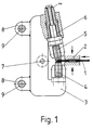
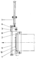
- 1 and 2 a simple rolling device installed at the end of a roller table directly in front of the coiler will be described.
- the sheet metal strip arriving on a roller table from the direction of the arrow abuts the raised stop 10 and the end face 1 of the sheet metal strip is precisely aligned.
- a light barrier (not shown) triggers the drive (not shown) of the clamping device 2.
- One side of the clamping device 2 is clamped, for example, by a pneumatic cylinder or hydraulic cylinder against the sheet metal strip and against the other side, with the pneumatic piston actuating a switch, not shown, in the end position, which switches on the drive for the stop 10 so that it is lowered .
- this also presses against a switch which switches on the displacement drive 7, so that the bracket 3 rolls with the rollers 4 and 5 along the beginning 1 of the sheet metal strip, its guide bushings 8 being guided in the guides 9 and the Edge of the sheet metal strip is rolled between the upper and lower rollers.
- the upper roller 5 is inclined so that the beginning 1 of the sheet metal strip is rolled in a wedge shape.
- the roll gap can be adjusted by the spindle 6.
- the roll gap can be made even narrower so that the sheet edge can be rolled even flatter.
- multiple rolling can also be achieved by installing a second pair of rolls with a narrower roll gap on the bracket behind the pair of rolls with the large roll gap.
Landscapes
- Engineering & Computer Science (AREA)
- Mechanical Engineering (AREA)
- Winding, Rewinding, Material Storage Devices (AREA)
- Wire Processing (AREA)
- Registering, Tensioning, Guiding Webs, And Rollers Therefor (AREA)
- Road Signs Or Road Markings (AREA)
- Replacement Of Web Rolls (AREA)
Description
- Die Erfindung betrifft ein Verfahren und eine Vorrichtung zur Kantenbearbeitung für das Aufwickeln von Coils. Beim Aufwickeln von Coils hinterläßt die am Anfang an der Stirnseite der innersten Windung liegende Blechkante bleibende Abdrücke auf den folgenden Windungen. Die Blechkante wird durch den Wickeldorn so stark gegen die nachfolgenden Windungen gedrückt, daß durch die Verformungen bis zu 15 Windungen unbrauchbar werden. Dies gilt besonders für die Automobilindustrie, wo kleinste Verformungen am fertigen Automobil noch sichtbar sind. In der DE 2414482 wird ein Blechband beschrieben, das an seinem Kopfende eine verringerte Dicke aufweist, die in einem kurzen Bereich bis zur vollen Dicke keilförmig ansteigt, wodurch ein Wickeln von dicken Walzbändern erleichtert werden soll. Diese keilförmige Abschrägung wird dabei durch stärkere Anstellung des oder der letzten Gerüste der Walzstraße erreicht, wobei diese Gerüste nach Einlaufen des Bandes wieder in die Position auseinandergefahren werden, die sie zum Walzen des Walzbandes einzunehmen haben. Dieses Verfahren ist aber nur in Breitband- und Kaltwalzwerken anwendbar, da für das Abschrägen des Bandes auf seiner ganzen Breite sehr hohe Walzdrücke erforderlich sind, nicht in Oberflächenveredlungs-, Umwickel- und/oder Zerteilanlagen. Ein weiterer Nachteil liegt darin, daß noch eine kleine Kante am Anfang des Blechbandes vorhanden ist, die geringe Abdrücke verursachen kann. Die Aufgabe der Erfindung besteht darin, ein Verfahren und eine Vorrichtung zum Herstellen einer mit geringen Kräften herstellbaren Abschrägung ohne Kanten am Anfang des Blechbandes bei Blechbändern zu schaffen, wobei die Vorrichtung direkt vor der Haspelanlage angeordnet werden soll. Die Aufgabe der Erfindung wird durch die Merkmale des Patentanspruch 1 gelöst, wobei sich besonders vorteilhaft auswirkt, wenn die Abschrägung des Blechbandes an der dem Durchmesser des aufzuwickelnden Coils zugewandten Seite angebracht wird. Die hohe Geschwindigkeit des Walzens stellt sicher, daß der Produktionsfluß nicht gestört wird. An Hand der Fig. 1 und 2 wird eine am Ende eines Rollganges direkt vor der Haspelanlage eingebaute einfache Walzvorrichtung beschrieben. Das auf einem Rollgang aus der Pfeilrichtung ankommende Blechband stößt gegen den hochgefahrenen Anschlag 10 und die Stirnseite 1 des Blechbandes wird dabei genau ausgerichtet. Sobald das Blechband den Anschlag 10 erreicht hat, löst eine nicht gezeichnete Lichtschranke den ebenfalls nicht gezeichneten Antrieb der Klemmvorrrichtung 2 aus. Die eine Seite der Klemmvorrichtung 2 wird z.B. durch einen Pneumatikzylinder oder Hydraulikzylinder gegen das Blechband und gegen die andere Seite klemmend gefahren, wobei er Pneumatikkolben in der Endstellung einen nicht gezeichneten Schalter betätigt, der den Antrieb für den Anschlag 10 einschaltet, so daß dieser abgesenkt wird. In der untersten Stellung des Anschlages drückt dieser ebenfalls gegen einen Schalter, der den Verschiebeantrieb 7 einschaltet, so daß der Bügel 3 mit den Walzen 4 und 5 entlang dem Anfang 1 des Blechbandes rollt, wobei seine Führungsbuchsen 8 in den Führungen 9 geführt werden und die Kante des Blechbandes zwischen der oberen und der unteren Walze gewalzt wird. Die obere Walze 5 ist schräg gestellt, so daß der Anfang 1 des Blechbandes keilförmig spitz gewalzt wird. Der Walzspalt ist durch die Spindel 6 verstellbar. Beim Rückhub kann Walzspalt noch enger gestellt werden, so daß die Blechkante noch flacher gewalzt werden kann. Bei großen Blechdicken ist ein mehrfaches Walzen auch dadurch erreichbar, daß in Walzrichtung hinter dem Walzenpaar mit dem großen Walzspalt ein zweites Walzenpaar mit engerem Walzspalt am Bügel eingebaut ist.
Claims (5)
Priority Applications (1)
| Application Number | Priority Date | Filing Date | Title |
|---|---|---|---|
| AT88118046T ATE66837T1 (de) | 1987-12-10 | 1988-10-29 | Verfahren und vorrichtung zur kantenbearbeitung zum aufwickeln von coils. |
Applications Claiming Priority (2)
| Application Number | Priority Date | Filing Date | Title |
|---|---|---|---|
| DE3741895A DE3741895C1 (de) | 1987-12-10 | 1987-12-10 | Verfahren und Vorrichtung zum Vorbereiten von Band fuer das Aufwickeln zu Bandbunden |
| DE3741895 | 1987-12-10 |
Publications (3)
| Publication Number | Publication Date |
|---|---|
| EP0319696A2 EP0319696A2 (de) | 1989-06-14 |
| EP0319696A3 EP0319696A3 (en) | 1989-10-25 |
| EP0319696B1 true EP0319696B1 (de) | 1991-09-04 |
Family
ID=6342309
Family Applications (1)
| Application Number | Title | Priority Date | Filing Date |
|---|---|---|---|
| EP88118046A Expired - Lifetime EP0319696B1 (de) | 1987-12-10 | 1988-10-29 | Verfahren und Vorrichtung zur Kantenbearbeitung zum Aufwickeln von Coils |
Country Status (5)
| Country | Link |
|---|---|
| EP (1) | EP0319696B1 (de) |
| AT (1) | ATE66837T1 (de) |
| DE (2) | DE3741895C1 (de) |
| ES (1) | ES2009716B3 (de) |
| GR (2) | GR890300085T1 (de) |
Families Citing this family (2)
| Publication number | Priority date | Publication date | Assignee | Title |
|---|---|---|---|---|
| AT410185B (de) * | 2000-05-26 | 2003-02-25 | Johannes Stari Tech Consulting | Vorrichtung zum niederhalten und glätten von blechkanten |
| CN118768435B (zh) * | 2024-09-05 | 2024-12-31 | 苏州百狮腾电气有限公司 | 一种电机端环滚边机 |
-
1987
- 1987-12-10 DE DE3741895A patent/DE3741895C1/de not_active Expired
-
1988
- 1988-10-29 EP EP88118046A patent/EP0319696B1/de not_active Expired - Lifetime
- 1988-10-29 DE DE8888118046T patent/DE3864668D1/de not_active Expired - Fee Related
- 1988-10-29 ES ES88118046T patent/ES2009716B3/es not_active Expired - Lifetime
- 1988-10-29 AT AT88118046T patent/ATE66837T1/de not_active IP Right Cessation
-
1989
- 1989-10-31 GR GR89300085T patent/GR890300085T1/el unknown
-
1991
- 1991-09-05 GR GR91401251T patent/GR3002650T3/el unknown
Also Published As
| Publication number | Publication date |
|---|---|
| DE3864668D1 (de) | 1991-10-10 |
| EP0319696A2 (de) | 1989-06-14 |
| EP0319696A3 (en) | 1989-10-25 |
| ES2009716B3 (es) | 1992-03-16 |
| ES2009716A4 (es) | 1989-10-16 |
| GR890300085T1 (en) | 1989-10-31 |
| DE3741895C1 (de) | 1988-09-22 |
| GR3002650T3 (en) | 1993-01-25 |
| ATE66837T1 (de) | 1991-09-15 |
Similar Documents
| Publication | Publication Date | Title |
|---|---|---|
| DE2256024C2 (de) | Warmwalzanlage für metallisches Walzgut | |
| DE4310547C2 (de) | Verfahren und Vorrichtung zum Verhindern der seitlichen Verbiegung einer sich längs erstreckenden, gewalzten Bramme | |
| DE2950473C2 (de) | ||
| DE3431691C2 (de) | Vorrichtung zur Regelung der Planheit und der Dicke von Walzband in einem Mehrwalzen-Bandwalzgerüst | |
| EP1456421B1 (de) | Verfahren und einrichtung zum kontrollierten richten und kühlen von aus einem warmband-walzwerk auslaufendem, breitem metallband, insbesondere von stahlband oder blech | |
| EP1330324A1 (de) | Kompakte kreismesserschere | |
| DE69429880T2 (de) | Planiergruppe in blechband streckrichtmaschinen mit arbeitsrollen von zunehmendem durchmesser | |
| DE2017306A1 (de) | ||
| DE3622926C2 (de) | Kontinuierliches mehrstufiges Walzwerk | |
| DE2648864A1 (de) | Verfahren zum strangpressen von metallen mit hoher dickenabnahme | |
| DE2437545B2 (de) | Verfahren zum Walzen von Metallstäben | |
| DE2642583B2 (de) | Schweißmaschine zum Verbinden von Bandstahlabschnitten | |
| DE2641573A1 (de) | Druckpresse zum biegen des randstreifens eines ebenen bleches | |
| DE69109945T2 (de) | Umkehrbares Walzverfahren. | |
| DE4417274A1 (de) | Verfahren zum Betreiben eines Walzgerüstes | |
| DE3741895C1 (de) | Verfahren und Vorrichtung zum Vorbereiten von Band fuer das Aufwickeln zu Bandbunden | |
| EP0703014B1 (de) | Verfahren zum Walzen von Hohlblöcken auf einem Asselwalzwerk | |
| EP1786577B1 (de) | Verfahren zum walzen eines metallbands | |
| DE3510862A1 (de) | Verfahren zum beidseitigen besaeumen und anschliessenden laengsteilen von blechen, insbesondere grobblechen, sowie scherenlinie zur ausuebung des verfahrens | |
| DE4028542C2 (de) | ||
| DE1452834A1 (de) | Vorrichtung zum Abflachen und Einrollen von Metallstreifen | |
| DE4201471C2 (de) | Verfahren und Vorrichtung zum Bearbeiten von Schweißnähten, um Überdicken im Nahtbereich von Bandverbindungen durch partielles Walzen zu vermeiden | |
| DE1777021A1 (de) | Verfahren zum Herstellen elektrisch geschweisster Rohre | |
| DE10218575A1 (de) | Trennvorrichtung für bandförmiges Halbzeug mit Sollbruchstellen | |
| EP0879100B1 (de) | Verfahren zum reversierwalzen von band sowie einrichtung zur durchführung des verfahrens |
Legal Events
| Date | Code | Title | Description |
|---|---|---|---|
| PUAI | Public reference made under article 153(3) epc to a published international application that has entered the european phase |
Free format text: ORIGINAL CODE: 0009012 |
|
| AK | Designated contracting states |
Kind code of ref document: A2 Designated state(s): AT BE CH DE ES FR GB GR IT LI LU NL SE |
|
| ITCL | It: translation for ep claims filed |
Representative=s name: RICCARDI SERGIO & CO. |
|
| TCNL | Nl: translation of patent claims filed | ||
| GBC | Gb: translation of claims filed (gb section 78(7)/1977) | ||
| EL | Fr: translation of claims filed | ||
| PUAL | Search report despatched |
Free format text: ORIGINAL CODE: 0009013 |
|
| AK | Designated contracting states |
Kind code of ref document: A3 Designated state(s): AT BE CH DE ES FR GB GR IT LI LU NL SE |
|
| RIN1 | Information on inventor provided before grant (corrected) |
Inventor name: RICKE, FRANZ Inventor name: WITTKOWSKI, BERND Inventor name: PEPPLER, WERNER Inventor name: VERHEIEN, JUERGEN Inventor name: HAHN, BERND Inventor name: EFSELMANN, ULRICH |
|
| 17P | Request for examination filed |
Effective date: 19891118 |
|
| 17Q | First examination report despatched |
Effective date: 19900928 |
|
| GRAA | (expected) grant |
Free format text: ORIGINAL CODE: 0009210 |
|
| AK | Designated contracting states |
Kind code of ref document: B1 Designated state(s): AT BE CH DE ES FR GB GR IT LI LU NL SE |
|
| REF | Corresponds to: |
Ref document number: 66837 Country of ref document: AT Date of ref document: 19910915 Kind code of ref document: T |
|
| REF | Corresponds to: |
Ref document number: 3864668 Country of ref document: DE Date of ref document: 19911010 |
|
| ET | Fr: translation filed | ||
| GBT | Gb: translation of ep patent filed (gb section 77(6)(a)/1977) | ||
| ITF | It: translation for a ep patent filed | ||
| REG | Reference to a national code |
Ref country code: ES Ref legal event code: FG2A Ref document number: 2009716 Country of ref document: ES Kind code of ref document: B3 |
|
| PLBE | No opposition filed within time limit |
Free format text: ORIGINAL CODE: 0009261 |
|
| STAA | Information on the status of an ep patent application or granted ep patent |
Free format text: STATUS: NO OPPOSITION FILED WITHIN TIME LIMIT |
|
| 26N | No opposition filed | ||
| REG | Reference to a national code |
Ref country code: GR Ref legal event code: FG4A Free format text: 3002650 |
|
| EPTA | Lu: last paid annual fee | ||
| EAL | Se: european patent in force in sweden |
Ref document number: 88118046.7 |
|
| PGFP | Annual fee paid to national office [announced via postgrant information from national office to epo] |
Ref country code: LU Payment date: 19960901 Year of fee payment: 9 |
|
| PGFP | Annual fee paid to national office [announced via postgrant information from national office to epo] |
Ref country code: GB Payment date: 19960916 Year of fee payment: 9 |
|
| PGFP | Annual fee paid to national office [announced via postgrant information from national office to epo] |
Ref country code: FR Payment date: 19960920 Year of fee payment: 9 Ref country code: DE Payment date: 19960920 Year of fee payment: 9 Ref country code: CH Payment date: 19960920 Year of fee payment: 9 |
|
| PGFP | Annual fee paid to national office [announced via postgrant information from national office to epo] |
Ref country code: SE Payment date: 19960923 Year of fee payment: 9 Ref country code: AT Payment date: 19960923 Year of fee payment: 9 |
|
| PGFP | Annual fee paid to national office [announced via postgrant information from national office to epo] |
Ref country code: BE Payment date: 19960924 Year of fee payment: 9 |
|
| PGFP | Annual fee paid to national office [announced via postgrant information from national office to epo] |
Ref country code: GR Payment date: 19960927 Year of fee payment: 9 |
|
| PGFP | Annual fee paid to national office [announced via postgrant information from national office to epo] |
Ref country code: NL Payment date: 19960930 Year of fee payment: 9 |
|
| PGFP | Annual fee paid to national office [announced via postgrant information from national office to epo] |
Ref country code: ES Payment date: 19961018 Year of fee payment: 9 |
|
| PG25 | Lapsed in a contracting state [announced via postgrant information from national office to epo] |
Ref country code: LU Free format text: LAPSE BECAUSE OF NON-PAYMENT OF DUE FEES Effective date: 19971029 Ref country code: GB Free format text: LAPSE BECAUSE OF NON-PAYMENT OF DUE FEES Effective date: 19971029 Ref country code: AT Free format text: LAPSE BECAUSE OF NON-PAYMENT OF DUE FEES Effective date: 19971029 |
|
| PG25 | Lapsed in a contracting state [announced via postgrant information from national office to epo] |
Ref country code: SE Free format text: LAPSE BECAUSE OF NON-PAYMENT OF DUE FEES Effective date: 19971030 Ref country code: ES Free format text: LAPSE BECAUSE OF THE APPLICANT RENOUNCES Effective date: 19971030 |
|
| PG25 | Lapsed in a contracting state [announced via postgrant information from national office to epo] |
Ref country code: LI Free format text: LAPSE BECAUSE OF NON-PAYMENT OF DUE FEES Effective date: 19971031 Ref country code: FR Free format text: THE PATENT HAS BEEN ANNULLED BY A DECISION OF A NATIONAL AUTHORITY Effective date: 19971031 Ref country code: CH Free format text: LAPSE BECAUSE OF NON-PAYMENT OF DUE FEES Effective date: 19971031 Ref country code: BE Free format text: LAPSE BECAUSE OF NON-PAYMENT OF DUE FEES Effective date: 19971031 |
|
| BERE | Be: lapsed |
Owner name: HOESCH STAHL A.G. Effective date: 19971031 |
|
| PG25 | Lapsed in a contracting state [announced via postgrant information from national office to epo] |
Ref country code: NL Free format text: LAPSE BECAUSE OF NON-PAYMENT OF DUE FEES Effective date: 19980501 |
|
| PG25 | Lapsed in a contracting state [announced via postgrant information from national office to epo] |
Ref country code: GR Free format text: LAPSE BECAUSE OF NON-PAYMENT OF DUE FEES Effective date: 19980513 |
|
| REG | Reference to a national code |
Ref country code: CH Ref legal event code: PL |
|
| GBPC | Gb: european patent ceased through non-payment of renewal fee |
Effective date: 19971029 |
|
| NLV4 | Nl: lapsed or anulled due to non-payment of the annual fee |
Effective date: 19980501 |
|
| PG25 | Lapsed in a contracting state [announced via postgrant information from national office to epo] |
Ref country code: DE Free format text: LAPSE BECAUSE OF NON-PAYMENT OF DUE FEES Effective date: 19980701 |
|
| EUG | Se: european patent has lapsed |
Ref document number: 88118046.7 |
|
| REG | Reference to a national code |
Ref country code: FR Ref legal event code: ST |
|
| REG | Reference to a national code |
Ref country code: ES Ref legal event code: FD2A Effective date: 20001102 |
|
| PG25 | Lapsed in a contracting state [announced via postgrant information from national office to epo] |
Ref country code: IT Free format text: LAPSE BECAUSE OF NON-PAYMENT OF DUE FEES;WARNING: LAPSES OF ITALIAN PATENTS WITH EFFECTIVE DATE BEFORE 2007 MAY HAVE OCCURRED AT ANY TIME BEFORE 2007. THE CORRECT EFFECTIVE DATE MAY BE DIFFERENT FROM THE ONE RECORDED. Effective date: 20051029 |