EP0319005A2 - Récipient muni d'une fermeture - Google Patents
Récipient muni d'une fermeture Download PDFInfo
- Publication number
- EP0319005A2 EP0319005A2 EP88120093A EP88120093A EP0319005A2 EP 0319005 A2 EP0319005 A2 EP 0319005A2 EP 88120093 A EP88120093 A EP 88120093A EP 88120093 A EP88120093 A EP 88120093A EP 0319005 A2 EP0319005 A2 EP 0319005A2
- Authority
- EP
- European Patent Office
- Prior art keywords
- container according
- container
- closure
- ring
- fastening ring
- Prior art date
- Legal status (The legal status is an assumption and is not a legal conclusion. Google has not performed a legal analysis and makes no representation as to the accuracy of the status listed.)
- Granted
Links
Images

Classifications
-
- B—PERFORMING OPERATIONS; TRANSPORTING
- B65—CONVEYING; PACKING; STORING; HANDLING THIN OR FILAMENTARY MATERIAL
- B65D—CONTAINERS FOR STORAGE OR TRANSPORT OF ARTICLES OR MATERIALS, e.g. BAGS, BARRELS, BOTTLES, BOXES, CANS, CARTONS, CRATES, DRUMS, JARS, TANKS, HOPPERS, FORWARDING CONTAINERS; ACCESSORIES, CLOSURES, OR FITTINGS THEREFOR; PACKAGING ELEMENTS; PACKAGES
- B65D47/00—Closures with filling and discharging, or with discharging, devices
- B65D47/04—Closures with discharging devices other than pumps
- B65D47/06—Closures with discharging devices other than pumps with pouring spouts or tubes; with discharge nozzles or passages
- B65D47/061—Closures with discharging devices other than pumps with pouring spouts or tubes; with discharge nozzles or passages with telescopic, retractable or reversible spouts, tubes or nozzles
- B65D47/063—Closures with discharging devices other than pumps with pouring spouts or tubes; with discharge nozzles or passages with telescopic, retractable or reversible spouts, tubes or nozzles with flexible parts
-
- B—PERFORMING OPERATIONS; TRANSPORTING
- B65—CONVEYING; PACKING; STORING; HANDLING THIN OR FILAMENTARY MATERIAL
- B65D—CONTAINERS FOR STORAGE OR TRANSPORT OF ARTICLES OR MATERIALS, e.g. BAGS, BARRELS, BOTTLES, BOXES, CANS, CARTONS, CRATES, DRUMS, JARS, TANKS, HOPPERS, FORWARDING CONTAINERS; ACCESSORIES, CLOSURES, OR FITTINGS THEREFOR; PACKAGING ELEMENTS; PACKAGES
- B65D47/00—Closures with filling and discharging, or with discharging, devices
- B65D47/04—Closures with discharging devices other than pumps
- B65D47/06—Closures with discharging devices other than pumps with pouring spouts or tubes; with discharge nozzles or passages
- B65D47/10—Closures with discharging devices other than pumps with pouring spouts or tubes; with discharge nozzles or passages having frangible closures
- B65D47/103—Membranes with a tearing element
Definitions
- the invention relates to a container with a removal opening and a closure closing this, in which the removal opening is overlaid by a container neck, on the end face of which a flange of the base part of the closure is held by a fastening ring which engages over this and engages behind a collar of the container neck, the flange of the base part of the closure lies sealingly on the collar of the container neck and / or a tube attachment of the closure, which is preferably equipped with sealing lips, engages sealingly in the container neck.
- Such a container is known from DE-OS 35 36 514.
- the container shown there as an exemplary embodiment, made of plastic has an integrally molded-on container neck, the free end of which is reinforced by a circumferential collar.
- the teaching of this laid-open document is expressly not limited to containers which are made of plastic, so that containers made of sheet metal can also be connected to an associated closure made of plastic with a similar fastening ring. It was already known beforehand to connect closures to container sockets made of sheet metal; in this context, however, only retaining rings made of sheet metal were used, which were clipped after the closure was put on, ie deformed in this way after the application were that the lower area of the ring jacket entered in the container neck annular beads.
- the teaching given in DE-OS 35 36 514 proves to be extremely advantageous: in the desired manner, the fastening rings used there can be applied by simple, centric pressing onto the container neck in such a way that the pressing of the sealing tube attachment of the closure in same operation can be performed. It has proven to be advantageous in the case of containers made of metal that they can be produced with much smaller tolerances than plastic containers in which the sealing process is often impaired by voids-like surface defects. When using containers made of sheet metal, there is thus the possibility of getting by with a lower height of the sealing lips of the tube attachment and also of reducing the number of sealing lips, so that a shorter tube attachment becomes possible. Such an approach can also be carried out with a reduced length, so that on the one hand the problem of residual emptying is easier to solve and on the other hand the length of the container neck can also be reduced.
- the invention is based on the task of creating a container made of sheet metal, which can be easily connected to a closure by means of a fastening ring, while at the same time the problems of residual emptying, perfect sealing and the operability of the closure are to be solved as far as possible and additionally Requirement for visible visibility of the opening of the container is taken into account.
- An easy and simple to manufacture and connectivity favoring container neck can be formed according to the teachings of claim 1: From the area of the opening of the lid of a container made of sheet metal, the container neck is pressed out as a short, tubular element, and the possibility of connection by a retaining ring the upper or outer end of this tube is folded outwards / downwards. This flipping can be done as a simple, flange-like bending outwards in the radial or axis-normal direction; A further improvement in durability, in particular, for example, in the case of deformation or drop tests, can be achieved if the outer upper end of the container neck is formed into a bead.
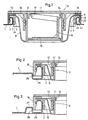
- a lid 1 of a container made of sheet metal is broken off, in which regions of the lid 1 are pressed upwards to form a tubular container neck 2, the upper edge of which is rolled over to form an outward bead 3, to form the removal opening, which shows a circular arc section extending approximately 180 ° as a profile.
- the base part 4 of a closure made of plastic is pressed in such a way that its flange 5 lies on the bulge 3 of the container socket and the pipe socket 6 passes through the container socket 2 under pretensioning of its sealing lips.
- the narrow tolerances of the container neck are sufficient to completely seal relatively few sealing lips 7, so that a tubular extension 6 of a relatively small height is required, which also results in a small height of the container neck 2.
- the tube extension extends with an essentially cylindrical part body 24 over the length of the container socket 2, so that its lower interface to favor the residual emptiness of the container at the level of the lower surface of the lid 1.
- a pouring spout 9 is connected to the base part 4, which in the exemplary embodiment shows a threaded attachment 10 on which a screw cap 12 is provided in a sealing manner, the head plate 11 of which is equipped with webs with handle brackets 13 which can be swiveled upwards.
- the top plate also has a sealing lug 14 which engages in the pouring spout 9.
- the pouring spout 9 is connected to a sealing disc 15, which can be torn out by means of a pull tab 16, the handling of which is facilitated by a grip ring 17.
- the closure is held in a sealing manner by a fastening ring 18 which overlaps with an upper leg 19 edge regions of the flange 5 of the closure, and the jacket 20 of which is equipped in the lower region of its inside with an annular bead 22 acting as a lower leg.
- a fastening ring 18 which overlaps with an upper leg 19 edge regions of the flange 5 of the closure, and the jacket 20 of which is equipped in the lower region of its inside with an annular bead 22 acting as a lower leg.
- U-shaped cross section can be used, in which the upper leg 19 and the jacket 20 can run according to those of FIG. 1.
- the sheet will be formed solely in the yoke attachment to the jacket 20 or by different bending points so that at least the last section of this lower leg extends inwards and upwards or in the direction of the plane of the upper leg.
- fastening rings made of sheet metal not only prove to be advantageous compared to conventional clinching rings, but also show some of their disadvantages.
- the wall of containers is elastically deformed within a certain range, and further deformations result in at least a remaining proportion of deformation. This affects both the container neck 2 and the beaded rim surrounding it.
- a clinching ring or a metal fastening ring also shows similar properties: Within a certain deformation range, there are purely elastic deformations, and deformations that exceed this elastic range leave permanent deformations that practically never match the permanent deformations of the container neck and the bead edge, and thus due to Different permanent deformations and mutual elastic tension affect the sealing of the closure. In the case of using the recommended plastic fastening rings, however, there is no permanent permanent deformation of the same, but a relatively high degree of adaptability, so that even after relatively strong permanent deformations of the container neck and its bulge, a fastening ring made of plastic after attempts to drop the closure still can keep sealed. If existing plastic fastening rings due to their deformability the lock to be fixed safely and Tar On the other hand, keeping sealed must also ensure that any possibility of deliberately inadmissible removal of the retaining ring is prevented.
- Such a bead can be molded into the cover 1 in the simplest case according to FIG. 2.
- Such a bead here consists of the falling flank 25, which tightly and tightly encompasses at least lower regions of the fastening ring 18.
- the base of the bead which is designed as a ring region 26, can already have the container neck 2, the outer end of which locks the fastening ring 18 by means of its ring bead.
- a downward-facing bead impairs the ability of the container to be emptied, therefore, according to FIG.
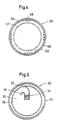
- FIG. 4 An example of such a fastening ring 29 is shown in FIG. 4.
- This fastening ring 29 has a relatively sturdy jacket 65 and also a relatively strong upper profile leg 66. However, it is not a continuous annular bead 22 of FIG. 1 that is used here as an undercut and for engaging behind a bead 3 of a container neck 2, but rather an annular bead provided only in sections 69 arranged in regular division.
- the fastening ring 29 is at the same time designed so that when assembling closures this is facilitated and, on the other hand, when a container is opened, the spout is inevitably only pulled out of its starting position shown in FIG 12 or 37 is unscrewed to break open the container.
- the inner jacket of the upper leg 66 is provided with a toothing 67 directed towards the center, and, in the exemplary embodiment with gaps in the sections 69 of the annular bulge, sawtooth-like locking teeth 68 are formed or molded into the lower surface of the upper leg 66. Accordingly, the top surface of the
- Flange 5 of the closure used is equipped with a suitably continuous locking toothing corresponding to the locking teeth 68, and the associated screw cap, as will be explained with reference to FIG. 6, has radially projecting ribs 40 which are able to engage in the toothing 67.
- the associated screw cap 37 is initially tightened in a sealing manner. After the container has cracked, this happens completely unhindered, always with the pouring spout pulled out. After closing the pouring spout by appropriately tightening the screw cap, this can be pushed back into its starting position if necessary.
- a fastening ring 30 is shown in the view from below in FIG. 5.
- the jacket 31 of the fastening ring 30 in turn has an annular bead divided into sections 32. Between the upper profile legs of the fastening ring, made in one piece with this, a cover surface 33 is provided, which is delimited against the upper legs by a trough 36 provided as a predetermined breaking point.
- the cover surface 33 provided as a locking washer can be separated by pulling on the pull tab 34 accordingly.
- the troughs 35 and 36 provided on both sides of this tear tab allow triggering of areas of the cover surface 33 adjacent to the tear tab 34 until finally, when the retaining ring is pulled further, tears along the trough 36 until the cover surface 33 is finally separated.
- sealing disk When fastening closures by means of clinching rings, it is known to hold a sealing disk, preferably made of sheet metal, with a small overlap, and it is also known to weld sealing foils consisting of metal foil and laminated with plastic onto a closure consisting of plastic.
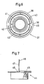
- FIG. 8 which will be explained in more detail later, when fastening by means of fastening rings 50, it is possible to insert such a sealing film, which may consist of a printed metal foil or also plastic-laminated and printed metal foil, into the fastening ring before it is applied.
- the sealing disk 52 formed by the film expediently extends to the inner wall of the jacket of the fastening ring 50, and its simple insertion avoids laborious work processes, for example welding or gluing.
- FIG. 6 A view from below of a further screw cap 37 is shown with reference to FIG. 6.
- the head disc is equipped with lateral webs 49, to which handle brackets 38, each enclosing the head disc of the screw cap 37, approximately semi-circularly, are connected by a trough which makes it easier to fold up.
- handlebars 38 are folded up so that they can be gripped behind for pulling out the pouring spout and can then also serve as a handle during unscrewing.
- a raised ring is provided as the centering 39 and corresponds in its outer diameter approximately to the inside width of the toothing 67 of FIG. 4.
- Ribs 40 which attach radially to the centering 39 are able to enter the tooth gaps of the toothing 67 of the fastening ring of FIG. 4 and the screw cap against this. Screwing on is provided with an internally threaded thread attachment 41, while a sealing attachment 42 also attached to the top plate 43 can sealingly engage in the opening of the pouring spout 9.
- FIG. 6 a further screw cap 44 is shown in FIG. 6, the top plate 45 of which is designed with a first thickness on the right side and is offset in the middle to a smaller thickness.
- a tab 46 which is equipped with a grip hole 47, is connected to the transition point of the head disc 44 via a film hinge.
- a cam 48 is also molded on. In the illustrated position of the tab, the screw cap 44 can be sprayed relatively easily.
- a fastening ring equipped with a sealing disk for example according to FIG.
- FIG. 8 shows a closure with fastening ring 50 overlapping it, in which a sealing film 52 is clamped between the upper leg of the fastening ring 50 and the flange 51 of the base part of the closure, as already described.
- the base part 53 of this closure has a substantially cylindrical part body 54 which leads to the lower surface of the lid of the container receiving the closure. From there close ß conical lugs 55 for easier insertion of the closure, which are arranged to facilitate the residual emptying of the container with gaps provided between them, ensuring the outflow of the container contents. Because of the narrow tolerances within which the container sockets of sheet metal containers can be manufactured, sufficient sealing is already possible with a correspondingly pre-stressed cylindrical part body without the need for special ribs. At the same time, however, it is shown that the flange can be produced with a tubular extension 62 which can at least partially encompass the collar of the container neck and on the one hand permits secure positioning and on the other hand improves the sealing options.
- a further variant of a closure is shown, in which is made in one piece with the flange of the retaining ring, so that in the hardness and elasticity correspondingly adjusted plastic material can be dispensed with a separate fastening ring and the flange 59 with its ring approach over the Bundle of a container neck is pressed so that the annular bead 61 provided inside engages behind the collar or edge bead of the container neck.
- the base region 57 of the base part 46 can be of double-conical design, so that a type of sealing lip results, and in the manner already described, the central application is facilitated by conical projections 58.
- separate sealing lips can be provided on the underside of the flange 59, and the annular bead 61 can be designed intermittently or interrupted to facilitate the pressing on.
- sealing disks On the one hand, it is required that they should be able to be assembled without additional work, if possible, but also that they should indicate an impermissible opening with the greatest possible security. Films welded onto closures or inserted into fastening rings are considered safe, but require additional work processes. Sealing disks connected with fastening rings are said, however, that after an impermissible opening, for example, they can be glued in again in an apparently perfect position, since they are directly behind surfaces as an adhesive base.
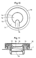
- One remedy here is a withdrawal of at least parts of the closure in connection with a division of the sealing disk, in which at least a part is exposed above its base. A corresponding arrangement with multiple seals is shown in FIGS. 10 and 11.
- FIG. 10 shows the top view of a fastening ring 70, which both has an outer sealing ring 71 and is equipped with an inner sealing disk 72 connected by this.
- the fastening ring, the sealing ring and the sealing disk are preferably produced in one piece and delimited from one another by rows of openings 73 and 74.
- the row 74 of openings is designed as a sensitive predetermined breaking point so that even when the sealing ring 71 is removed, but in particular when the tear tab 75 molded onto it, the connection between the sealing ring 71 and the sealing disk 72 along the row of openings 74 is destroyed .
- the sealing ring 71 lies on areas of the closure that underlie it, in particular the head disk 77 of the locking screw: However, below the sealing disk 72 the head disk has 77 has a recess 76, which makes it practically impossible to glue the sealing disk 72 onto parts of the closure which undercut it.
- This "divided sealing disc” does not pose any difficulties during production, the security against fraudulent manipulation is considerably increased.
- An additional sealing disk 78 within the closure itself can be dispensed with, but it can also be retained and supplemented by the sealing ring 71 and the sealing disk 72 in a clearly visible manner.
- the invention is neither limited to fastening rings made solely of plastic, nor to containers made from sheet metal.
- the annular bead 22 or sections 29 or 32 of the fastening rings 18, 24 or 30 are designed with a more inclined rear flank, the inclination required for fastening in extreme cases by undercuts designed as undercut saw teeth can be effected.
- closures with simple, free-standing removal openings, with extendable bellows or extendable, sealed pouring tubes can also be used, as can closures that are equipped with a rotatable plug for removal.
Landscapes
- Engineering & Computer Science (AREA)
- Mechanical Engineering (AREA)
- Closures For Containers (AREA)
Applications Claiming Priority (6)
| Application Number | Priority Date | Filing Date | Title |
|---|---|---|---|
| DE8715950U | 1987-12-02 | ||
| DE8715950U DE8715950U1 (fr) | 1987-12-02 | 1987-12-02 | |
| DE3805241 | 1988-02-19 | ||
| DE3805241 | 1988-02-19 | ||
| DE19883811362 DE3811362A1 (de) | 1987-12-02 | 1988-04-05 | Mit einem verschluss ausgestatteter behaelter |
| DE3811362 | 1988-04-05 |
Publications (3)
| Publication Number | Publication Date |
|---|---|
| EP0319005A2 true EP0319005A2 (fr) | 1989-06-07 |
| EP0319005A3 EP0319005A3 (en) | 1989-11-08 |
| EP0319005B1 EP0319005B1 (fr) | 1993-01-27 |
Family
ID=27197212
Family Applications (1)
| Application Number | Title | Priority Date | Filing Date |
|---|---|---|---|
| EP88120093A Expired - Lifetime EP0319005B1 (fr) | 1987-12-02 | 1988-12-01 | Récipient muni d'une fermeture |
Country Status (3)
| Country | Link |
|---|---|
| EP (1) | EP0319005B1 (fr) |
| DE (1) | DE3877922D1 (fr) |
| ES (1) | ES2037188T3 (fr) |
Cited By (5)
| Publication number | Priority date | Publication date | Assignee | Title |
|---|---|---|---|---|
| EP0380039A1 (fr) * | 1989-01-24 | 1990-08-01 | Heinrich Stolz GmbH & Co KG | Dispositif de fermeture pour ouvertures de remplissage de récipients |
| DE4041831A1 (de) * | 1990-12-24 | 1992-07-02 | Stolz Heinrich Gmbh | Verschluss fuer fuelloeffnungen von behaeltern |
| DE4130950A1 (de) * | 1991-09-18 | 1993-04-01 | Stolz Heinrich Gmbh | Verschluss mit einem auf einen behaelter mit behaelterstutzen aufrastbaren verschlussteil |
| EP1441961A1 (fr) * | 2001-10-12 | 2004-08-04 | Portola Packaging, Inc. | Fermeture avec capuchon et accessoire possedant un element de saisie |
| DE102011000902B3 (de) * | 2011-02-23 | 2011-12-22 | Kunststofftechnik Waidhofen An Der Thaya Gmbh | Verschluss zum Verschließen eines Behältnisses mit einem verschiebbaren Ausgabestutzen |
Citations (12)
| Publication number | Priority date | Publication date | Assignee | Title |
|---|---|---|---|---|
| US2561596A (en) * | 1947-06-05 | 1951-07-24 | Rieke Metal Products Corp | Container nestable and contractible pouring spout |
| US2565699A (en) * | 1948-05-13 | 1951-08-28 | Rieke Metal Products Corp | Flexible, retractable dispensing spout |
| US3250428A (en) * | 1964-03-09 | 1966-05-10 | Rieke Metal Products Corp | Means of attaching a closure to containers |
| FR1584609A (fr) * | 1967-08-02 | 1969-12-26 | ||
| DE2028806A1 (de) * | 1969-06-11 | 1971-01-14 | Aluminum Company of America, Pitts burgh, Pa (V St A) | Verschluß |
| FR2281279A1 (fr) * | 1974-08-07 | 1976-03-05 | Basse Indre Ets Jj Carnaud For | Boite notamment pour liquide alimentaire, tel que sirop de fruit |
| GB2076379A (en) * | 1980-05-12 | 1981-12-02 | Rieke Corp | Tamper-proof cap |
| FR2514330A1 (fr) * | 1981-10-08 | 1983-04-15 | Flextainer Ag | Bouchon-verseur inviolable en matiere synthetique s'adaptant a des reservoirs pour liquides |
| EP0144829A2 (fr) * | 1983-11-25 | 1985-06-19 | Jacob Berg GmbH & Co. KG | Fermeture pour récipient à goulot |
| DE8518074U1 (de) * | 1985-06-21 | 1986-02-20 | Henkel KGaA, 4000 Düsseldorf | Einteiliger, wiederverschließbarer Streuverschluß |
| DE3442344A1 (de) * | 1984-11-20 | 1986-05-22 | Jacob Berg GmbH & Co KG, 6501 Budenheim | Behaelterverschluss mit metallabdeckung |
| EP0246783A2 (fr) * | 1986-05-22 | 1987-11-25 | METAL BOX p.l.c. | Dispositif de retenue amovible pour le couvercle d'un récipient |
-
1988
- 1988-12-01 DE DE8888120093T patent/DE3877922D1/de not_active Expired - Lifetime
- 1988-12-01 EP EP88120093A patent/EP0319005B1/fr not_active Expired - Lifetime
- 1988-12-01 ES ES198888120093T patent/ES2037188T3/es not_active Expired - Lifetime
Patent Citations (12)
| Publication number | Priority date | Publication date | Assignee | Title |
|---|---|---|---|---|
| US2561596A (en) * | 1947-06-05 | 1951-07-24 | Rieke Metal Products Corp | Container nestable and contractible pouring spout |
| US2565699A (en) * | 1948-05-13 | 1951-08-28 | Rieke Metal Products Corp | Flexible, retractable dispensing spout |
| US3250428A (en) * | 1964-03-09 | 1966-05-10 | Rieke Metal Products Corp | Means of attaching a closure to containers |
| FR1584609A (fr) * | 1967-08-02 | 1969-12-26 | ||
| DE2028806A1 (de) * | 1969-06-11 | 1971-01-14 | Aluminum Company of America, Pitts burgh, Pa (V St A) | Verschluß |
| FR2281279A1 (fr) * | 1974-08-07 | 1976-03-05 | Basse Indre Ets Jj Carnaud For | Boite notamment pour liquide alimentaire, tel que sirop de fruit |
| GB2076379A (en) * | 1980-05-12 | 1981-12-02 | Rieke Corp | Tamper-proof cap |
| FR2514330A1 (fr) * | 1981-10-08 | 1983-04-15 | Flextainer Ag | Bouchon-verseur inviolable en matiere synthetique s'adaptant a des reservoirs pour liquides |
| EP0144829A2 (fr) * | 1983-11-25 | 1985-06-19 | Jacob Berg GmbH & Co. KG | Fermeture pour récipient à goulot |
| DE3442344A1 (de) * | 1984-11-20 | 1986-05-22 | Jacob Berg GmbH & Co KG, 6501 Budenheim | Behaelterverschluss mit metallabdeckung |
| DE8518074U1 (de) * | 1985-06-21 | 1986-02-20 | Henkel KGaA, 4000 Düsseldorf | Einteiliger, wiederverschließbarer Streuverschluß |
| EP0246783A2 (fr) * | 1986-05-22 | 1987-11-25 | METAL BOX p.l.c. | Dispositif de retenue amovible pour le couvercle d'un récipient |
Cited By (6)
| Publication number | Priority date | Publication date | Assignee | Title |
|---|---|---|---|---|
| EP0380039A1 (fr) * | 1989-01-24 | 1990-08-01 | Heinrich Stolz GmbH & Co KG | Dispositif de fermeture pour ouvertures de remplissage de récipients |
| DE4041831A1 (de) * | 1990-12-24 | 1992-07-02 | Stolz Heinrich Gmbh | Verschluss fuer fuelloeffnungen von behaeltern |
| DE4130950A1 (de) * | 1991-09-18 | 1993-04-01 | Stolz Heinrich Gmbh | Verschluss mit einem auf einen behaelter mit behaelterstutzen aufrastbaren verschlussteil |
| EP1441961A1 (fr) * | 2001-10-12 | 2004-08-04 | Portola Packaging, Inc. | Fermeture avec capuchon et accessoire possedant un element de saisie |
| EP1441961A4 (fr) * | 2001-10-12 | 2008-10-22 | Portola Packaging Inc | Fermeture avec capuchon et accessoire possedant un element de saisie |
| DE102011000902B3 (de) * | 2011-02-23 | 2011-12-22 | Kunststofftechnik Waidhofen An Der Thaya Gmbh | Verschluss zum Verschließen eines Behältnisses mit einem verschiebbaren Ausgabestutzen |
Also Published As
| Publication number | Publication date |
|---|---|
| EP0319005B1 (fr) | 1993-01-27 |
| EP0319005A3 (en) | 1989-11-08 |
| DE3877922D1 (de) | 1993-03-11 |
| ES2037188T3 (es) | 1993-06-16 |
Similar Documents
| Publication | Publication Date | Title |
|---|---|---|
| EP0086970B1 (fr) | Construction et procédé de montage d'un capuchon ainsi que capuchon pour un col de récipient muni d'un pas de vis ou d'un bourrelet | |
| DE4314923C2 (de) | Verschlußkappe zum Verschließen einer Flasche | |
| EP1976764B1 (fr) | Systeme d'ouverture refermable realise a partir d'un produit semi-fini et procede pour son montage | |
| DE3422546C2 (de) | Behälter-Verschlußkappe | |
| DE3041972A1 (de) | Verschlusskappe und verfahren zu ihrer herstellung | |
| DE3226910A1 (de) | Schutzklammer | |
| DE3422547A1 (de) | Manipuliersichere verschlusskappe fuer behaelter | |
| EP0675051B1 (fr) | Capuchon à vis avec un anneau soudé | |
| EP0462390A2 (fr) | Emballage comprenant plusieurs matériaux différents | |
| DE2405939A1 (de) | Behaelter, insbesondere zum vakuumabdichtenden verschliessen | |
| EP0319005A2 (fr) | Récipient muni d'une fermeture | |
| DE3426427A1 (de) | Flaschenverschluss | |
| DE2233305A1 (de) | Schraubverschluss mit originalitaetssicherungsring | |
| DE3811362A1 (de) | Mit einem verschluss ausgestatteter behaelter | |
| EP0537601A1 (fr) | Bouchon pour récipient | |
| EP0216268B1 (fr) | Récipient en plastique avec une fermeture | |
| EP1281627B1 (fr) | Ensemble fermeture/récipient avec garantie d'inviolabilité | |
| EP1529005B1 (fr) | Dispositif de fermeture/deversement combine comprenant une securite d'authenticite | |
| DE19851331A1 (de) | Verschlußkappe für Gewindehalsflaschen | |
| EP0904237A1 (fr) | Bouchon de recipient et embouchure de recipient | |
| EP1700790B1 (fr) | Tube pour substances pâteuses ou similaires | |
| EP0498954B2 (fr) | Capuchon de fermeture pour fermeture en matière plastique | |
| DE4204977A1 (de) | Kindersicherheitsverschluss | |
| EP1632435B1 (fr) | Tube et moyens de bouchage pour des tubes | |
| DE19653065A1 (de) | Verpackung |
Legal Events
| Date | Code | Title | Description |
|---|---|---|---|
| PUAI | Public reference made under article 153(3) epc to a published international application that has entered the european phase |
Free format text: ORIGINAL CODE: 0009012 |
|
| 17P | Request for examination filed |
Effective date: 19881219 |
|
| AK | Designated contracting states |
Kind code of ref document: A2 Designated state(s): BE CH DE ES FR GB IT LI NL SE |
|
| PUAL | Search report despatched |
Free format text: ORIGINAL CODE: 0009013 |
|
| AK | Designated contracting states |
Kind code of ref document: A3 Designated state(s): BE CH DE ES FR GB IT LI NL SE |
|
| RAP1 | Party data changed (applicant data changed or rights of an application transferred) |
Owner name: HEINRICH STOLZ GMBH & CO KG |
|
| 17Q | First examination report despatched |
Effective date: 19911206 |
|
| ITF | It: translation for a ep patent filed |
Owner name: DE DOMINICIS & MAYER S. |
|
| GRAA | (expected) grant |
Free format text: ORIGINAL CODE: 0009210 |
|
| AK | Designated contracting states |
Kind code of ref document: B1 Designated state(s): BE CH DE ES FR GB IT LI NL SE |
|
| ET | Fr: translation filed | ||
| REF | Corresponds to: |
Ref document number: 3877922 Country of ref document: DE Date of ref document: 19930311 |
|
| GBT | Gb: translation of ep patent filed (gb section 77(6)(a)/1977) |
Effective date: 19930429 |
|
| REG | Reference to a national code |
Ref country code: ES Ref legal event code: FG2A Ref document number: 2037188 Country of ref document: ES Kind code of ref document: T3 |
|
| PLBE | No opposition filed within time limit |
Free format text: ORIGINAL CODE: 0009261 |
|
| STAA | Information on the status of an ep patent application or granted ep patent |
Free format text: STATUS: NO OPPOSITION FILED WITHIN TIME LIMIT |
|
| 26N | No opposition filed | ||
| EAL | Se: european patent in force in sweden |
Ref document number: 88120093.5 |
|
| PGFP | Annual fee paid to national office [announced via postgrant information from national office to epo] |
Ref country code: BE Payment date: 20000204 Year of fee payment: 12 |
|
| PG25 | Lapsed in a contracting state [announced via postgrant information from national office to epo] |
Ref country code: BE Free format text: LAPSE BECAUSE OF NON-PAYMENT OF DUE FEES Effective date: 20001231 |
|
| BERE | Be: lapsed |
Owner name: HEINRICH STOLZ G.M.B.H. & CO. K.G. Effective date: 20001231 |
|
| REG | Reference to a national code |
Ref country code: GB Ref legal event code: IF02 |
|
| REG | Reference to a national code |
Ref country code: CH Ref legal event code: PFA Owner name: HEINRICH STOLZ GMBH & CO. KG Free format text: HEINRICH STOLZ GMBH & CO. KG#IN DER AU 13#D-57290 NEUNKIRCHEN (DE) -TRANSFER TO- HEINRICH STOLZ GMBH & CO. KG#IN DER AU 13#D-57290 NEUNKIRCHEN (DE) |
|
| PGFP | Annual fee paid to national office [announced via postgrant information from national office to epo] |
Ref country code: NL Payment date: 20071213 Year of fee payment: 20 |
|
| PGFP | Annual fee paid to national office [announced via postgrant information from national office to epo] |
Ref country code: IT Payment date: 20071222 Year of fee payment: 20 Ref country code: CH Payment date: 20071217 Year of fee payment: 20 |
|
| PGFP | Annual fee paid to national office [announced via postgrant information from national office to epo] |
Ref country code: SE Payment date: 20071213 Year of fee payment: 20 |
|
| PGFP | Annual fee paid to national office [announced via postgrant information from national office to epo] |
Ref country code: GB Payment date: 20071218 Year of fee payment: 20 Ref country code: ES Payment date: 20071228 Year of fee payment: 20 |
|
| PGFP | Annual fee paid to national office [announced via postgrant information from national office to epo] |
Ref country code: DE Payment date: 20071221 Year of fee payment: 20 |
|
| PGFP | Annual fee paid to national office [announced via postgrant information from national office to epo] |
Ref country code: FR Payment date: 20071217 Year of fee payment: 20 |
|
| REG | Reference to a national code |
Ref country code: CH Ref legal event code: PL |
|
| REG | Reference to a national code |
Ref country code: GB Ref legal event code: PE20 Expiry date: 20081130 |
|
| PG25 | Lapsed in a contracting state [announced via postgrant information from national office to epo] |
Ref country code: NL Free format text: LAPSE BECAUSE OF EXPIRATION OF PROTECTION Effective date: 20081201 |
|
| EUG | Se: european patent has lapsed | ||
| REG | Reference to a national code |
Ref country code: ES Ref legal event code: FD2A Effective date: 20081202 |
|
| PG25 | Lapsed in a contracting state [announced via postgrant information from national office to epo] |
Ref country code: ES Free format text: LAPSE BECAUSE OF EXPIRATION OF PROTECTION Effective date: 20081202 |
|
| PG25 | Lapsed in a contracting state [announced via postgrant information from national office to epo] |
Ref country code: GB Free format text: LAPSE BECAUSE OF EXPIRATION OF PROTECTION Effective date: 20081130 |