EP0318912A2 - Optischer Kopf - Google Patents
Optischer Kopf Download PDFInfo
- Publication number
- EP0318912A2 EP0318912A2 EP88119870A EP88119870A EP0318912A2 EP 0318912 A2 EP0318912 A2 EP 0318912A2 EP 88119870 A EP88119870 A EP 88119870A EP 88119870 A EP88119870 A EP 88119870A EP 0318912 A2 EP0318912 A2 EP 0318912A2
- Authority
- EP
- European Patent Office
- Prior art keywords
- lens
- reflection type
- grating lens
- optical head
- light
- Prior art date
- Legal status (The legal status is an assumption and is not a legal conclusion. Google has not performed a legal analysis and makes no representation as to the accuracy of the status listed.)
- Granted
Links
Images


Classifications
-
- G—PHYSICS
- G11—INFORMATION STORAGE
- G11B—INFORMATION STORAGE BASED ON RELATIVE MOVEMENT BETWEEN RECORD CARRIER AND TRANSDUCER
- G11B7/00—Recording or reproducing by optical means, e.g. recording using a thermal beam of optical radiation by modifying optical properties or the physical structure, reproducing using an optical beam at lower power by sensing optical properties; Record carriers therefor
- G11B7/12—Heads, e.g. forming of the optical beam spot or modulation of the optical beam
- G11B7/135—Means for guiding the beam from the source to the record carrier or from the record carrier to the detector
- G11B7/1381—Non-lens elements for altering the properties of the beam, e.g. knife edges, slits, filters or stops
-
- G—PHYSICS
- G11—INFORMATION STORAGE
- G11B—INFORMATION STORAGE BASED ON RELATIVE MOVEMENT BETWEEN RECORD CARRIER AND TRANSDUCER
- G11B7/00—Recording or reproducing by optical means, e.g. recording using a thermal beam of optical radiation by modifying optical properties or the physical structure, reproducing using an optical beam at lower power by sensing optical properties; Record carriers therefor
- G11B7/08—Disposition or mounting of heads or light sources relatively to record carriers
- G11B7/09—Disposition or mounting of heads or light sources relatively to record carriers with provision for moving the light beam or focus plane for the purpose of maintaining alignment of the light beam relative to the record carrier during transducing operation, e.g. to compensate for surface irregularities of the latter or for track following
- G11B7/0901—Disposition or mounting of heads or light sources relatively to record carriers with provision for moving the light beam or focus plane for the purpose of maintaining alignment of the light beam relative to the record carrier during transducing operation, e.g. to compensate for surface irregularities of the latter or for track following for track following only
- G11B7/0903—Multi-beam tracking systems
-
- G—PHYSICS
- G11—INFORMATION STORAGE
- G11B—INFORMATION STORAGE BASED ON RELATIVE MOVEMENT BETWEEN RECORD CARRIER AND TRANSDUCER
- G11B7/00—Recording or reproducing by optical means, e.g. recording using a thermal beam of optical radiation by modifying optical properties or the physical structure, reproducing using an optical beam at lower power by sensing optical properties; Record carriers therefor
- G11B7/08—Disposition or mounting of heads or light sources relatively to record carriers
- G11B7/09—Disposition or mounting of heads or light sources relatively to record carriers with provision for moving the light beam or focus plane for the purpose of maintaining alignment of the light beam relative to the record carrier during transducing operation, e.g. to compensate for surface irregularities of the latter or for track following
- G11B7/0908—Disposition or mounting of heads or light sources relatively to record carriers with provision for moving the light beam or focus plane for the purpose of maintaining alignment of the light beam relative to the record carrier during transducing operation, e.g. to compensate for surface irregularities of the latter or for track following for focusing only
- G11B7/0912—Disposition or mounting of heads or light sources relatively to record carriers with provision for moving the light beam or focus plane for the purpose of maintaining alignment of the light beam relative to the record carrier during transducing operation, e.g. to compensate for surface irregularities of the latter or for track following for focusing only by push-pull method
-
- G—PHYSICS
- G11—INFORMATION STORAGE
- G11B—INFORMATION STORAGE BASED ON RELATIVE MOVEMENT BETWEEN RECORD CARRIER AND TRANSDUCER
- G11B7/00—Recording or reproducing by optical means, e.g. recording using a thermal beam of optical radiation by modifying optical properties or the physical structure, reproducing using an optical beam at lower power by sensing optical properties; Record carriers therefor
- G11B7/08—Disposition or mounting of heads or light sources relatively to record carriers
- G11B7/09—Disposition or mounting of heads or light sources relatively to record carriers with provision for moving the light beam or focus plane for the purpose of maintaining alignment of the light beam relative to the record carrier during transducing operation, e.g. to compensate for surface irregularities of the latter or for track following
- G11B7/0908—Disposition or mounting of heads or light sources relatively to record carriers with provision for moving the light beam or focus plane for the purpose of maintaining alignment of the light beam relative to the record carrier during transducing operation, e.g. to compensate for surface irregularities of the latter or for track following for focusing only
- G11B7/0916—Foucault or knife-edge methods
-
- G—PHYSICS
- G11—INFORMATION STORAGE
- G11B—INFORMATION STORAGE BASED ON RELATIVE MOVEMENT BETWEEN RECORD CARRIER AND TRANSDUCER
- G11B7/00—Recording or reproducing by optical means, e.g. recording using a thermal beam of optical radiation by modifying optical properties or the physical structure, reproducing using an optical beam at lower power by sensing optical properties; Record carriers therefor
- G11B7/12—Heads, e.g. forming of the optical beam spot or modulation of the optical beam
- G11B7/135—Means for guiding the beam from the source to the record carrier or from the record carrier to the detector
- G11B7/1353—Diffractive elements, e.g. holograms or gratings
-
- G—PHYSICS
- G11—INFORMATION STORAGE
- G11B—INFORMATION STORAGE BASED ON RELATIVE MOVEMENT BETWEEN RECORD CARRIER AND TRANSDUCER
- G11B7/00—Recording or reproducing by optical means, e.g. recording using a thermal beam of optical radiation by modifying optical properties or the physical structure, reproducing using an optical beam at lower power by sensing optical properties; Record carriers therefor
- G11B7/12—Heads, e.g. forming of the optical beam spot or modulation of the optical beam
- G11B7/135—Means for guiding the beam from the source to the record carrier or from the record carrier to the detector
- G11B7/1372—Lenses
- G11B7/1378—Separate aberration correction lenses; Cylindrical lenses to generate astigmatism; Beam expanders
Definitions
- the present invention relates to an optical head by which informations are recorded into and read out of a recording medium such as an optical disk, magnetooptical disk, etc.
- One of the conventional optical heads comprises a collimating lens for collimating laser beam radiated from a semiconductor laser, a beam splitter for transmitting the laser beam therethrough and for reflecting beam reflected from an optical disk, a total reflection prism for reflecting the beam transmitted through the beam splitter and the optical disk-reflected beam to bend a light path thereof by 90°, a first focusing lens for focusing the beam on the optical disk, a 1/2 wavelength plate for rotating a polarization of the beam reflected from the beam splitter by 90°, a second focusing lens for focusing the beam transmitted through the 1/2 wavelenlgth plate, a polarizing beam splitter for transmitting and reflecting the beam focused by the second focusing lens to produce two beams having polarizations orthogonal to each other, a two-divided photodetector for receiving the beam transmitted through the polarizing beam splitter, a cylindrical lens for transmitting the beam reflected by the polarizing beam splitter to produce beam of astigmatism wave surface, and a four-divide
- a tracking error is detected in a push-pull method by using signals of the two-divided photodetector
- a focusing error is detected in an astigmatism method by using signals of the four-divided photodetector
- a RF signals are obtained in accordance with a predetermined calculation based on the signals of the two and four-divided photodetectors, although the details thereof and operation will be explained in more detail later.
- the conventional optical head has a relatively large size, for example, greater than 40x40x30 mm2, and thus this prevents miniaturization and lightening of the entire optical disk system.
- a push-pull method has generally been utilized for detecting a tracking error. Therefore, when the first focusing lens is moved in the direction normal to its optical axis by means of an actuator on the basis of the tracking error signals, the deviation may arise between the optical axis of the first focusing lens and the dividing line of the two-divided photodetector for detecting the tracking error to induce the imbalance between two quantities of light which are incident to two photodetector elements respectively. As a result, a direct current offset is generated in the tracking error signals, thereby resulting in a limited range of the tracking error controlling.
- such a conventional optical head has a number of optical parts required to be optically polished, and thus this is expensive and their adjustments are complex and cumbrous.
- the optical head further comprises a total reflection prism for compensating a phase difference between polarized beams which are incident to the means for detecting the RF signal, and this total reflection prism is provided between the disk and a polarizing prism to be positioned on an optical axis of the beam reflected from the disk, the polarizing prism being positioned between the reflection type grating device and the means for detecting the RF signal.
- Fig. 1 shows a conventional optical head.
- a laser beam 2 radiated from a semiconductor laser 1 is collimated as collimated beam 4 by a collimating lens 3
- the beam 4 is transmitted through a beam splitter 5
- the transmitted beam is reflected by a total reflection prism 6 to bend a light path of the reflected beam by an angle of 90°
- the reflected beam is then focused onto the surface of a disk 8 by a first focusing lens 7.
- the beam reflected from the surface of the disk 8 is propagated in the reverse direction and then is reflected by the beam splitter 5.
- the reflected beam is focused by a second focusing lens 9, and then focused beam is divided, by a polarizing beam splitter 10, into a transmitted beam 11 and a reflected beam 12, polarizations of which are orthogonal to each other.
- the transmitted beam 11 is received in a two-divided photodetector 13 in which a tracking error signal can be obtained from the subtraction between two signal of photodetector elements 14 and 15.
- the reflected beam 12 is passed through a cylindrical lens 16 to form an astigmatism wave surface and then is received in a four-divided photodetector 17 in which a focusing error signal can be obtained by an astigmatism method. That is, when the output voltages of photodector elements 18, 19, 20 and 21 in the four-divided photodector 17 are V18, V19, V20 and V21 respectively, the focusing error signal can be obtained in the equation of V18 + V20 - V19 - V21.
- a RF signal can be obtained from the subtraction between the intensities of two polarized beams divided by the polarizing beam splitter 10, polarizations of which are orthogonal to each other. This means that, when the output voltages of the photodetector elements 14 and 15 are V14 and V15 respectively, the RF signal can be obtained in the equation of V14 + V15 - V18 - V19 - V20 - V21.
- Fig. 2 is a perspective view showing the basic construction of a first embodiment according to the present invention.
- the laser beam 2 radiated from a semiconductor laser 1 is transmitted through a beam splitter 5, the transmitted beam is collimated as a collimated beam 4 by a collimating lens 3, the collimated beam 4 is subject to total reflection by a total reflection prism 6, so that a light path of the reflected beam is bent by an angle of 90°, and then the reflected beam is focused on the surface of an optical or magnetooptical disk 8 by a focusing lens 7.
- the beam reflected from the surface of the disk 8 follows the light path as described above in the reverse direction thereof, the beam is focused by the collimating lens 3, and the focused beam is reflected by the beam splitter 5.
- the reflected beam is diffracted by a reflection type grating lens 23 and the diffracted beam is received in a six-divided photodector 34 comprising photodector elements or devices 28 to 33.
- the zero-order diffracted beam is reflected from the reflection type grating lens 23, and then divided into two polarized beams orthogonal to each other in polarization by a polarizing prism 24 and the polarized beams are received in a two-divided photodetector 27 comprising photodetector elements 25 and 26.
- Fig. 3 is a partially enlarged perspective view showing the relationship between the reflection type grating lens 23 and the six-divided photodector 27 as shown in Fig. 1.
- Fig. 3 there are shown the focusing lens 7 and the disk 8 by use of cut-off lines 35 so as to show the directional relationship between four domains on the grating lens 23 and tracks provided on the disk 8.
- the reflection type grating lens 23 consists of A or a first domain 39, B or a second domain 40, C or a third domain 41 and D or a fourth domain 42.
- the domains A and B which are different from each other in focal length and direction of diffraction are bounded by a dividing line 38 intersecting an optical axis of the collimating lens 3.
- the domains C and D which are different from the domains A and B in focal length and direction of diffraction are formed on the dividing line 38.
- the reflection type grating lens 39 of the domain A has a grating pattern corresponding to interference fringes produced by an interference between a spherical wave reflected on the plane of the grating lens 39 and is focused on a focal point of the zero-order diffraction light 51 and a spherical wave diverging from a point 43 on a first dividing line 47 of the six-divided photodetector 34.
- the reflection type grating lens 40 of the domain B has a grating pattern corresponding to interference fringes produced by an interference between a spherical wave reflected on the plane of the grating lens 40 and is focused to a focal point of the zero-order diffraction light 51 and a spherical wave diverging from a point 44 on the dividing line 47.
- the reflecting type grating lens 41 of the domain C has a grating pattern corresponding to interference fringes produced by an interference between a spherical wave reflected on the plane of the grating lens 41 and is focused to a focal point of the zero order diffraction light 51 and a spherical wave diverging from a point 45 on a photodetector element 33 of the six-divided photodetector 34.
- the reflection type grating lens 42 of the domain D has a grating pattern corresponding to interference fringes produced by an interference between a spherical wave reflected on the plane of the grating lens 42 and is focused to a focal point of the zero-order diffraction light 51 and a spherical wave diverging from a point 46 on a photodector element 32 of the six-divided photodetector 34.
- a grating lens 23 is used, light which is reflected from the disk 8 is then incident to the reflection type grating lens 23 is focused to the points 43, 44, 45 and 46 on the six-divided photodetector 34 as diffracted beams 49, 50, 36 and 37 respectively.
- the zero-order diffraction beam which is not subject to the diffraction is divided to two polarized beams by a polarizing prism 24, and the two polarized beams are focused on the photodetector elements 25 and 26 of the two-divided photodetector 27.
- a RF signal can be obtained from a differential signal between the two photodetector elements 25 and 26.
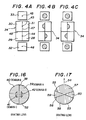
- Figs. 4A, 4B and 4C show the states of diffracted beams on the six-divided photodetector 34.
- Fig. 4A shows a focused state in which beams are focused on the disk 8.
- the beam 49 diffracted from the reflection type grating lens 39 of the domain A and the beam 50 diffracted from the reflection type grating lens 40 of the domain B are focused on a first dividing line 47 and on the opposite sides of a second dividing line 48 respectively.
- Fig. 4B shows a defocused state in which the disk 8 is positioned on a longer distance than the focused state from the focusing lens 7.
- Fig. 4C shows a defocused state in which the disk 8 is positioned closer than the focused state to the focusing lens 7.
- the diffracted beams 49 and 50 are incident to the photodetector elements 31 and 29 of the six-divided photodetector 34 respectively, but they are not incident to the photodetector elements 30 and 28.
- the focusing error signal can be obtained in the equation, ( S1 + S4 ) - ( S2 + S3 ).
- a tracking error signal can be obtained by utilizing the imbalance in intensity distributions of the reflected lights in a case where a spot focused on the disk 8 is deviated from the center of a track. That is, the grating lens 23 is set in such an arrangement that the line connecting the centers of the reflection type grating lenses 41 and 42 of the domains C and D includes the point at which an optical axis of the focusing lens 7 intersects with the grating lens, and is parallel to the direction of a tracking error on the disk 8.
- the difference in quantities of lights can be detected as an output difference between the two photodector elements 32 and 33 of the six-divided photodetector 34, and the direction of the tracking error can also be detected depending on whether a resulting signal is positive or negative.
- a fluctuation in a wavelength of a semiconductor laser changes an angle of diffraction, thereby resulting in a deviation in the position of diffracted beam on a photodector element.
- first and second directions in which the first direction is a direction parallel to the first dividing line 47, and the second direction is a normal to the second dividing line 48.
- the positional change in the direction parallel to the first dividing line 47 may be left out of consideration unless it crosses over the second dividing line 48, and gets out of the photodetector 34.
- the positional change in the direction normal to the first dividing line 47 it is required to take a necessary step in a conventional optical head because the outputs of the central four photodetector elements 28, 29, 30 and 31 in the six-divided photodetector 34 change.
- the domains A and B of the reflection type grating lens 23 have hardly a spatial frequency in that direction, so that the positional change of diffracted beam in the direction can be disregarded.
- a system for detecting a tracking error in which a push-pull method is employed to move a focusing lens for the correction of the tracking error, the optical axis of an optical slystem on an error detecting side may deviate from the optical axis on a lens side, thereby producing a difference in quantity of light received in a photodetector for detecting a tracking error, so that an offset is induced in a signal of the tracking error.
- the reflection type grating lenses 41 and 42 for the domains C and D are of an equal area and arranged symmetrically in regard to an optical axis to detect light beam from the beam splitter 5.
- the first dividing line 47 of the six-divided photodetector 34 is normal to the direction of a track on the disk 8.
- this arrangement of the six-divided photodetector 34 may be changed.
- the six-divided photodetector may be rotated in regard to an optical axis of incident light for the reflection type grating lens 23 by an arbitrary angle along with the dividing line 38 of the reflection type grating lens 23.
- the arrangement of the photodetector elements 32 and 33 are not limited to that shown in Figs. 2 and 3.
- a reflection type grating lens is used.
- the reflection type grating lens is a device or element, a reflecting surface of which has conductivity.
- the surface of the grating is coated with an electric conductor such as aluminium, gold, etc.
- the reflection type grating lens In addition to the diffraction of the first-order diffraction light, the reflection type grating lens reflects the zero-order diffracted light directly.
- a RF signal can be obtained by receiving the zero-order diffracted light.
- a read signal from a disk includes a very small component of signal polarized light. Therefore, the zero-order diffraction light which is incident to a RF signal receiving system is desired to include a large component of signal polarized light as much as possible. That is, it is desired to use a reflection type grating lens which does not diffract such a signal polarized light component.
- the invention adopts a grating having a ratio of a wavelength to a groove spacing (pitch): ⁇ /d ⁇ 0.5 or ⁇ /d ⁇ 1.2, where ⁇ is a wavelength, and d is a groove spacing.
- Figs. 5 to 10 show ⁇ /d dependent characteristics of reflection type diffraction efficiencies for reflection type diffraction gratings each having rectangular grooves. These data are reported in the following paper: E. G. Loewen, et al., "Efficiency optimization of rectangular groove gratings for use in the visible and IR regions", Applied Optics Vol. 18, No. 3, pp. 2262-2266 (1979).
- a/d is a ratio of a groove width "a" to a groove spacing "d”
- h/d is a ratio of a groove depth "h” to the groove spacing "d”.
- the diffraction efficiency of P-polarized light comes to nearly zero at ⁇ /d ⁇ 1.2. Therefore, it is preferable to utilize P-polarized light as a signal polarized light component.
- P-polarized light may also be utilized as a signal polarized light component.
- the reflection type grating lens is divided into two domains having different characteristics from each other, thereby permitting a border line to provide an action equivalent to that of a knife edge used in a conventional optical head.
- a tracking error signal can also be obtained by forming two domains having gratings disposed in different directions from each other at the respective positions lightly separated from the center point at which an optical axis of a collimating lens intersects with the grating lens, wherein intensities of light beams diffracted from these two domains are compared according to the principle of a push-pull method.
- a RF signal can be detected by a differential detecting method.
- a magnetooptical disk system utilizes Kerr effect by which a plane of polarization is rotated to read informations from a disk.
- Fig. 11 shows the states of polarized lights both before and after being reflected from a disk.
- the polarization plane of light reflected from the disk is rotated relative to the polarization plane of incident light.
- the direction of this rotation depends on the existence of a recorded signal.
- the angle of this rotation is very small and is of the order of about 0.2 degrees, and the signal polarized light components 64 and 65 produced by this rotation is small.
- it is required to transmit the signal polarized light components 64 and 65 to a signal system with a low loss and to provide a detecting method having an improved efficiency.
- the present invitation utilizes a reflection type grating lens having a polarized light dependence on the diffraction efficiency described above.
- a method of differential detection is a useful means as a method of detection.
- a polarizing prism which has an optical axis inclined relative to X axis by 45°, is inserted between a grating a grating lens and a two-divided photodetector, so that signal polarized light beams 61 and 62 are divided to two components, respectively, one of which is in a direction 66 parallel to this optical axis of the polarizing prism, and the other of which is in a direction 67 normal to the optical axis, and the divided signals are transmitted to the two-divided photodetector, correspondingly.
- the RF signals can be obtained from the difference between these two signal voltages.
- the reflection type grating lens according to the present invention has a function of a reflection-diffraction type beam splitter by which incident light is divided into a RF signal light, a focusing error detecting signal light, and a tracking error detecting signal light.
- the optical head according to the invention can therefore have a small number of parts, and is simple in adjustment, and thus a miniaturized, lightened and inexpensive optical head can be obtained.
- the present invention adopts an optical construction to compensate a phase difference between polarized beams produced by a reflection type grating lens.
- a reflection type grating lens When the surface of a grating lens is coated with a metal film, polarized light parallel to a direction of grooves of the grating lens differs in phase changes after reflection from polarized light perpendicular to the direction of the grooves, thereby resulting in a phase difference therebetween.
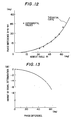
- Fig. 12 shows the phase difference between such polarized beams dependent on an incident angle to a reflection plane, when the surface of a grating lens is coated with gold film. When an incident angle is 60°, the grating lens produces a phase difference of 45° which is slightly greater than a value in a case of a mere metal surface.
- the signal polarized light component 64 produced by Kerr effect shown in Fig. 11 is coincided with the polarized component 65 perpendicular to the component in the direction of polarization described above, so that a C/N ratio of regenerated signal is lowered due to a phase difference produced by reflection.
- Fig. 13 shows a relationship between such a phase difference (degrees) and an amount of signal deterioration (dB). Regenerated signal at a phase difference of 90° can not be detected. Accordingly, it is necessary to insert a phase compensating plate capable of compensating a phase difference produced by reflection on a metal coated grating lens.
- a transmission type phase compensating plate using a double refracting crystal such as crystallized quartz is used for a phase compensating means, it is difficult to provide a compact optical system for an optical head.
- the present invention adopts a total reflection prism for a phase compensation means.
- this total reflection prism provides total reflection of the light, so that phase jumps of different values are generated in P and S-polarized lights.
- a phase compensation is realized in accordance with the phenomenon.
- Fig. 14 shows a curve of a phase difference between P and S-polarized lights dependent on a refractive index in which an incident angle is constant at 45°
- Fig. 15 shows a curve of the phase difference dependent on an incident angle in which the refractive index is constant at 1.5.
- This total reflection prism is of a reflection type, so that an optical system of an optical head can be folded up for providing a compact optical head device.
- a reflection type grating lens 52 in a second embodiment according to the present invention.
- a dividing line 38 of the reflection type grating lens 52 is rotated relative to that in the first embodiment by 90° as apparent from a comparison with Figs. 2 and 3.
- the relation between the grating lens 52 and the six-divided photodetector 34 is the same as that of the first embodiment. That is, as shown in Fig.
- beams diffracted from the reflection type grating lenses 39 and 40 are focused on the points 43 and 44 on the six-divided photodetector 34 respectively, and beams diffracted from the reflected from the reflection type grating lenses 41 and 42 are focused on the points 45 and 46 on the six-divided photodetector 34 respectively.
- Fig. 17 shows a reflection type grating lens in a third embodiment according to the present invention.
- the reflection type grating lens 53 is divided into four domains 57, 58, 59 and 60, which correspond to the domains A, B, C and D in the first embodiment, by two border lines 55 and 56. Therefore, this grating lens 53 can perform the same function as that of the first embodiment by setting a direction of optical disk tracks in a direction of an arrow 54.
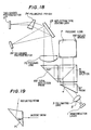
- Fig. 18 shows a fourth embodiment of an optical head according to the present invention, in which like numerals indicate like elements in Fig. 2.
- beam is risen up in a direction perpendicular to the surface of the drawings to a disk (not shown) by a reflex mirror 68 in a focusing lens 7.
- a reflection type grating lens 23 has a surface having a grating pitch of 1.4 ⁇ m and a grating depth of 0.14 ⁇ m and coated with gold film.
- a two-divided photodetector element 27 can receive signal light for a RF signal with a low loss, and tracking and focusing signals can be detected in accordance with 20% of the light diffracted based on the polarized light component perpendicular to the grating lens.
- a phase difference between polarized lights is compensated in reflection of light supplied from a polarizing beam splitter 5 by a total reflection prism 69.
- the total reflection prism 69 corresponds to the former means of the two means as described in the explanation of principle and operation. Where an incident angle is 45°, the total reflection prism 69 is of a glass having a refractive index of 1.55 to obtain a phase difference of 45° produced by a reflection type grating lens 23.
- reference numeral 67 is a prism, and 70 a focusing lens.
- Fig. 19 shows a total reflection prism 71 in a fifth embodiment according to the present invention which corresponds to the latter means of the two means described in the explanation of principle and operation.
- an incident angle of 50° is employed using a glass prism having a refractive index of 1.5.
- phase compensating means may be disposed in a specific position selected in a light path between a focusing lens 7 and a polarized prism 24.
- an optical part of a light receiving system comprises only a reflection type grating lens and a polarizing prism, so that a number of parts used in a conventional optical head is remarkably reduced to make the size of the optical head small.
- the reflection type grating lens used in the present invention is a surface concave-convex type device, a replica of the device can easily be obtained in a hot press or photopolymerization process, or the like by use of a metal mold, so that such a reflection type grating lens can be mass-produced inexpensively.
- the grating lens is provided with domains C and D to obtain a tracking error signal, so that a tracking offset due to the movement of a focusing lens does not occur. Still further, since the reflection type grating lens functions as a beam splitter, a RF signal and tracking and focusing error signals have only a slight interference thereamong. Therefore, servomotor is stable.
- the optical head of the present invention utilizes a total reflection prism as a phase compensating means, so that a compact optical head is obtained.
- an inexpensive glass can be utilized for the total reflection prism, and thus it is possible to provide an inexpensive optical head.
Landscapes
- Physics & Mathematics (AREA)
- Optics & Photonics (AREA)
- Optical Head (AREA)
- Optical Recording Or Reproduction (AREA)
Applications Claiming Priority (4)
| Application Number | Priority Date | Filing Date | Title |
|---|---|---|---|
| JP303529/87 | 1987-11-30 | ||
| JP62303529A JPH01144233A (ja) | 1987-11-30 | 1987-11-30 | 光ヘッド装置 |
| JP63164024A JPH0212620A (ja) | 1988-06-29 | 1988-06-29 | 光ヘッド装置 |
| JP164024/88 | 1988-06-29 |
Publications (3)
| Publication Number | Publication Date |
|---|---|
| EP0318912A2 true EP0318912A2 (de) | 1989-06-07 |
| EP0318912A3 EP0318912A3 (en) | 1990-07-04 |
| EP0318912B1 EP0318912B1 (de) | 1994-02-02 |
Family
ID=26489289
Family Applications (1)
| Application Number | Title | Priority Date | Filing Date |
|---|---|---|---|
| EP88119870A Expired - Lifetime EP0318912B1 (de) | 1987-11-30 | 1988-11-29 | Optischer Kopf |
Country Status (3)
| Country | Link |
|---|---|
| US (1) | US5036504A (de) |
| EP (1) | EP0318912B1 (de) |
| DE (1) | DE3887657T2 (de) |
Cited By (5)
| Publication number | Priority date | Publication date | Assignee | Title |
|---|---|---|---|---|
| EP0405432A2 (de) * | 1989-06-30 | 1991-01-02 | Honeywell Inc. | Aufzeichnungs-/Wiedergabekopf für eine optische Scheibe |
| EP0460368A2 (de) * | 1990-06-06 | 1991-12-11 | Matsushita Electric Industrial Co., Ltd. | Optischer Abtastkopf |
| EP0475523A1 (de) * | 1990-09-12 | 1992-03-18 | Koninklijke Philips Electronics N.V. | Vorrichtung zum Abtasten einer Informationsfläche mit optischer Strahlung |
| US5404344A (en) * | 1991-04-04 | 1995-04-04 | Hitachi, Ltd. | Recording/reproducing optical head producing focusing error signal from zero-th order diffracted light and tracking error signal from first order diffracted light |
| GB2300065A (en) * | 1995-04-18 | 1996-10-23 | Sony Corp | Optical pickup device |
Families Citing this family (4)
| Publication number | Priority date | Publication date | Assignee | Title |
|---|---|---|---|---|
| DE69015376T2 (de) * | 1989-01-20 | 1995-05-24 | Matsushita Electric Ind Co Ltd | Optische Kopfanordnung zur Verwendung in einem optischen Scheibensystem. |
| DE69319673T2 (de) * | 1992-08-12 | 1999-02-25 | Philips Electronics Nv | Einrichtung zur optischen Abtastung einer Oberfläche |
| JPH08212612A (ja) * | 1994-11-17 | 1996-08-20 | Canon Inc | 光学的情報記録再生装置及び該装置用光ヘッド |
| JP5751328B2 (ja) * | 2011-06-29 | 2015-07-22 | 株式会社ニコン | 構造化照明光学系および構造化照明顕微鏡装置 |
Citations (4)
| Publication number | Priority date | Publication date | Assignee | Title |
|---|---|---|---|---|
| JPS6161245A (ja) * | 1984-09-03 | 1986-03-29 | Nec Corp | 光学ヘツド |
| JPS61230634A (ja) * | 1985-04-05 | 1986-10-14 | Nec Corp | 光ヘツド |
| EP0228620A2 (de) * | 1985-12-10 | 1987-07-15 | Nec Corporation | Optischer Kopf mit einem Beugungsgitter zum Richten von zwei oder mehreren gebeugten Lichtstrahlen auf optische Detektoren |
| EP0273356A2 (de) * | 1986-12-25 | 1988-07-06 | Nec Corporation | Optischer Kopf |
Family Cites Families (6)
| Publication number | Priority date | Publication date | Assignee | Title |
|---|---|---|---|---|
| US4733065A (en) * | 1984-06-27 | 1988-03-22 | Canon Kabushiki Kaisha | Optical head device with diffraction grating for separating a light beam incident on an optical recording medium from a light beam reflected therefrom |
| NL8502835A (nl) * | 1985-10-17 | 1987-05-18 | Philips Nv | Inrichting voor het met optische straling aftasten van een informatievlak. |
| EP0241942B1 (de) * | 1986-04-18 | 1992-03-04 | Mitsubishi Denki Kabushiki Kaisha | Optischer Kopf |
| US4731772A (en) * | 1986-05-06 | 1988-03-15 | Lee Wai Hon | Optical head using hologram lens for both beam splitting and focus error detection functions |
| DE3786497T2 (de) * | 1986-07-18 | 1994-02-17 | Nec Corp | Doppelbrechendes Beugungsgitter und optischer Kopf, in welchem ein linearpolarisierter Strahl auf dieses Gitter gelenkt wird. |
| JPH0827965B2 (ja) * | 1986-08-29 | 1996-03-21 | 株式会社日立製作所 | 光学式再生装置 |
-
1988
- 1988-11-29 DE DE88119870T patent/DE3887657T2/de not_active Expired - Fee Related
- 1988-11-29 EP EP88119870A patent/EP0318912B1/de not_active Expired - Lifetime
- 1988-11-30 US US07/277,735 patent/US5036504A/en not_active Expired - Lifetime
Patent Citations (4)
| Publication number | Priority date | Publication date | Assignee | Title |
|---|---|---|---|---|
| JPS6161245A (ja) * | 1984-09-03 | 1986-03-29 | Nec Corp | 光学ヘツド |
| JPS61230634A (ja) * | 1985-04-05 | 1986-10-14 | Nec Corp | 光ヘツド |
| EP0228620A2 (de) * | 1985-12-10 | 1987-07-15 | Nec Corporation | Optischer Kopf mit einem Beugungsgitter zum Richten von zwei oder mehreren gebeugten Lichtstrahlen auf optische Detektoren |
| EP0273356A2 (de) * | 1986-12-25 | 1988-07-06 | Nec Corporation | Optischer Kopf |
Non-Patent Citations (2)
| Title |
|---|
| PATENT ABSTRACTS OF JAPAN vol. 10, no. 225 (P-484)(2281) 6 August 1986, & JP-A-61 61245 (NEC CORPORATION) 29 March 1986, * |
| PATENT ABSTRACTS OF JAPAN vol. 11, no. 68 (P-553)() 28 February 1987, & JP-A-61 230634 (NEC CORPORATION) 14 October 1986, * |
Cited By (11)
| Publication number | Priority date | Publication date | Assignee | Title |
|---|---|---|---|---|
| EP0405432A2 (de) * | 1989-06-30 | 1991-01-02 | Honeywell Inc. | Aufzeichnungs-/Wiedergabekopf für eine optische Scheibe |
| EP0405432A3 (en) * | 1989-06-30 | 1992-01-15 | Honeywell Inc. | Optical disk read/write head |
| EP0460368A2 (de) * | 1990-06-06 | 1991-12-11 | Matsushita Electric Industrial Co., Ltd. | Optischer Abtastkopf |
| EP0460368A3 (en) * | 1990-06-06 | 1992-02-05 | Matsushita Electric Industrial Co., Ltd. | Optical pickup head |
| US5293367A (en) * | 1990-06-06 | 1994-03-08 | Matsushita Electric Industrial Co., Ltd. | Optical pickup head wherein an error signal is produced by detecting a phase difference in diffraction beams from a holographic optical element |
| EP0475523A1 (de) * | 1990-09-12 | 1992-03-18 | Koninklijke Philips Electronics N.V. | Vorrichtung zum Abtasten einer Informationsfläche mit optischer Strahlung |
| US5404344A (en) * | 1991-04-04 | 1995-04-04 | Hitachi, Ltd. | Recording/reproducing optical head producing focusing error signal from zero-th order diffracted light and tracking error signal from first order diffracted light |
| GB2300065A (en) * | 1995-04-18 | 1996-10-23 | Sony Corp | Optical pickup device |
| US5684780A (en) * | 1995-04-18 | 1997-11-04 | Sony Corporation | Optical pickup device having optical element exhibiting polarized light selectivity loaded thereon and optical apparatus having the optical pickup device loaded thereon |
| GB2300065B (en) * | 1995-04-18 | 1999-09-22 | Sony Corp | Optical pickup device |
| CN1083599C (zh) * | 1995-04-18 | 2002-04-24 | 索尼公司 | 装有偏振选择性元件的光拾取器件和装该器件的光学装置 |
Also Published As
| Publication number | Publication date |
|---|---|
| US5036504A (en) | 1991-07-30 |
| DE3887657D1 (de) | 1994-03-17 |
| DE3887657T2 (de) | 1994-05-11 |
| EP0318912A3 (en) | 1990-07-04 |
| EP0318912B1 (de) | 1994-02-02 |
Similar Documents
| Publication | Publication Date | Title |
|---|---|---|
| US4733065A (en) | Optical head device with diffraction grating for separating a light beam incident on an optical recording medium from a light beam reflected therefrom | |
| US5231620A (en) | Magneto-optical recording/reproducing apparatus with light beam splitting means | |
| EP0390610B1 (de) | Optisches Element und dieses enthaltende optische Abtasteinrichtung | |
| EP0285126B1 (de) | Kopf für magnetooptisches Aufzeichnungsmedium | |
| EP0059084B1 (de) | Optisches Auslesegerät | |
| US5493555A (en) | Optical head using birefringent diffraction grating | |
| US5737296A (en) | Focus and tracking error detection by using plus and minus first order diffracted light | |
| US5570333A (en) | Head device for magneto-optical disk | |
| EP0318912B1 (de) | Optischer Kopf | |
| EP0547624B1 (de) | System für magneto-optischen Kopf | |
| US6266313B1 (en) | Optical pickup for recording or reproducing system | |
| JPS62117150A (ja) | 光学式ピツクアツプ | |
| US6556532B2 (en) | Optical pickup device | |
| JPS6117103A (ja) | 偏光ビ−ムスプリツタ | |
| JP3439903B2 (ja) | 光ディスク装置用光学ヘッド | |
| US6639888B1 (en) | Information reading and recording device for optical disk | |
| EP0534373B1 (de) | Optisches Wiedergabegerät | |
| JP2685790B2 (ja) | 偏光素子を含む光学系からなる装置 | |
| JP2857258B2 (ja) | 光ピックアップ装置 | |
| EP0484625A2 (de) | Gerät zur Wiedergabe von gespeicherten Daten | |
| JPS63311631A (ja) | 光ヘッド装置 | |
| JPH05114185A (ja) | 光磁気記録再生装置における光ピツクアツプ装置 | |
| KR0135859B1 (ko) | 광헤드 | |
| JPH06300921A (ja) | ホログラム素子及び光ヘッド装置 | |
| JPH0191344A (ja) | 光磁気記録媒体用ピックアップ |
Legal Events
| Date | Code | Title | Description |
|---|---|---|---|
| PUAI | Public reference made under article 153(3) epc to a published international application that has entered the european phase |
Free format text: ORIGINAL CODE: 0009012 |
|
| 17P | Request for examination filed |
Effective date: 19881129 |
|
| AK | Designated contracting states |
Kind code of ref document: A2 Designated state(s): DE FR GB NL |
|
| PUAL | Search report despatched |
Free format text: ORIGINAL CODE: 0009013 |
|
| AK | Designated contracting states |
Kind code of ref document: A3 Designated state(s): DE FR GB NL |
|
| RHK1 | Main classification (correction) |
Ipc: G11B 7/09 |
|
| 17Q | First examination report despatched |
Effective date: 19920513 |
|
| GRAA | (expected) grant |
Free format text: ORIGINAL CODE: 0009210 |
|
| AK | Designated contracting states |
Kind code of ref document: B1 Designated state(s): DE FR GB NL |
|
| PG25 | Lapsed in a contracting state [announced via postgrant information from national office to epo] |
Ref country code: NL Effective date: 19940202 |
|
| REF | Corresponds to: |
Ref document number: 3887657 Country of ref document: DE Date of ref document: 19940317 |
|
| ET | Fr: translation filed | ||
| NLV1 | Nl: lapsed or annulled due to failure to fulfill the requirements of art. 29p and 29m of the patents act | ||
| PGFP | Annual fee paid to national office [announced via postgrant information from national office to epo] |
Ref country code: FR Payment date: 19941115 Year of fee payment: 7 |
|
| PGFP | Annual fee paid to national office [announced via postgrant information from national office to epo] |
Ref country code: GB Payment date: 19941129 Year of fee payment: 7 |
|
| PLBE | No opposition filed within time limit |
Free format text: ORIGINAL CODE: 0009261 |
|
| STAA | Information on the status of an ep patent application or granted ep patent |
Free format text: STATUS: NO OPPOSITION FILED WITHIN TIME LIMIT |
|
| 26N | No opposition filed | ||
| PG25 | Lapsed in a contracting state [announced via postgrant information from national office to epo] |
Ref country code: DE Effective date: 19950801 |
|
| PG25 | Lapsed in a contracting state [announced via postgrant information from national office to epo] |
Ref country code: GB Effective date: 19951129 |
|
| GBPC | Gb: european patent ceased through non-payment of renewal fee |
Effective date: 19951129 |
|
| PG25 | Lapsed in a contracting state [announced via postgrant information from national office to epo] |
Ref country code: FR Effective date: 19960731 |
|
| REG | Reference to a national code |
Ref country code: FR Ref legal event code: ST |