EP0317502B1 - Vorrichtung zum Bestimmen der Planheit eines plattenförmigen Körpers - Google Patents
Vorrichtung zum Bestimmen der Planheit eines plattenförmigen Körpers Download PDFInfo
- Publication number
- EP0317502B1 EP0317502B1 EP88810746A EP88810746A EP0317502B1 EP 0317502 B1 EP0317502 B1 EP 0317502B1 EP 88810746 A EP88810746 A EP 88810746A EP 88810746 A EP88810746 A EP 88810746A EP 0317502 B1 EP0317502 B1 EP 0317502B1
- Authority
- EP
- European Patent Office
- Prior art keywords
- plate
- planar object
- beams
- piston
- king
- Prior art date
- Legal status (The legal status is an assumption and is not a legal conclusion. Google has not performed a legal analysis and makes no representation as to the accuracy of the status listed.)
- Expired - Lifetime
Links
Images

Classifications
-
- G—PHYSICS
- G01—MEASURING; TESTING
- G01B—MEASURING LENGTH, THICKNESS OR SIMILAR LINEAR DIMENSIONS; MEASURING ANGLES; MEASURING AREAS; MEASURING IRREGULARITIES OF SURFACES OR CONTOURS
- G01B7/00—Measuring arrangements characterised by the use of electric or magnetic techniques
- G01B7/28—Measuring arrangements characterised by the use of electric or magnetic techniques for measuring contours or curvatures
- G01B7/287—Measuring arrangements characterised by the use of electric or magnetic techniques for measuring contours or curvatures using a plurality of fixed, simultaneously operating transducers
-
- G—PHYSICS
- G01—MEASURING; TESTING
- G01B—MEASURING LENGTH, THICKNESS OR SIMILAR LINEAR DIMENSIONS; MEASURING ANGLES; MEASURING AREAS; MEASURING IRREGULARITIES OF SURFACES OR CONTOURS
- G01B5/00—Measuring arrangements characterised by the use of mechanical techniques
- G01B5/20—Measuring arrangements characterised by the use of mechanical techniques for measuring contours or curvatures
- G01B5/207—Measuring arrangements characterised by the use of mechanical techniques for measuring contours or curvatures using a plurality of fixed, simultaneously operating transducers
Definitions
- the invention relates to a device for determining the flatness of a plate-shaped body by measuring the relative spatial position of points on its surface, with a base on which the plate-shaped body lies freely during the measurement process.
- the flatness of a plate is usually determined by measuring the position of selected points on the plate surface relative to a solid base on which the plate lies during the measuring process. In the case of large-area thin plates in particular, however, the measurement result can be significantly falsified by the weight of the plate itself.
- the inventor has set itself the goal of providing a device of the type mentioned at the outset, with which the flatness of a thin plate can be determined in a simple manner by eliminating the influence of its own weight.
- the base consists of a plurality of regularly arranged and the plate-shaped body, each of which is essentially punctiform Support surface adjacent, vertically movable support beams, wherein the support beams are mechanically, hydraulically or pneumatically connected to each other in such a way that essentially the same force is transmitted from each support beam to the plate-shaped body.
- the weight of the plate-shaped body is distributed evenly over the individual support beams. This counteracts an additional warping of the plate under the influence of its own weight, so that its effective flatness can be measured on an overlying plate.
- the plate to be measured For optimum storage of the plate to be measured, it is mentally divided into a number of uniform partial surfaces corresponding to the number of support beams and the support points of the support beams on the plate are selected such that they are each in the center of gravity of a partial plate surface. This balances the dead weight of each sub-area at the point of contact and the remaining total plate deformation is only determined by the inner plate stresses.
- the device comprises a system of beams suspended in equilibrium in the manner of beam scales and arranged at right angles to one another, with each end of the beam simultaneously forming the fulcrum for the subsequent right-angled beam, and with the support beams directed vertically upwards onto the free beams Beam ends are set.
- the bar lengths are preferably matched to one another in such a way that the distances between adjacent support beams are the same within the two bar directions. This regular arrangement of the support points leads to an optimal storage of the plate to be measured.
- the hydraulic or pneumatic coupling of the Support beams are each placed on a piston of a cylinder / piston element and the cylinders are connected to one another via solid-walled hoses in the manner of communicating vessels.
- a regular arrangement of the cylinder / piston elements also leads to an optimal storage of the plate to be measured.
- the hydraulic or pneumatic version has the additional advantage that it can be easily adapted to any plate size by adding or leaving out cylinder / piston elements. Another possibility is to arrange the cylinder / piston elements so that they can be displaced in the horizontal direction in order to adapt to the respective size of the plate-shaped body.
- the flatness of the plate-shaped body is reproduced by the position of the support points of the support beams on the plate surface and can therefore be carried out in a simple manner, for example by measuring the bar inclinations or the piston positions in the cylinders, the mechanical displacements preferably being converted into electrical measurement signals.
- devices for determining the vertical position of the support beams can be provided.
- the actual flatness measurement can also be carried out independently of the support device - e.g. with a LASER scanner.
- the device according to the invention is also particularly suitable for in-line flatness measurement in a continuously operating production line.
- a mechanical embodiment of the device according to the invention consists of a system of support beams 1, cross beams 2, base beams 3 and a connecting beam 4. All support beams 1 are arranged parallel to one another and parallel to the base beams 3. The support beams 1 are connected in pairs via a cross beam 2 and these in turn are connected in pairs via a base beam 3. The connecting beam 4 lies between the two basic beams 3. The transverse beams 2 and the connecting beam 4 are at right angles to the support beams 1 and the basic beams 3. The joints between the beams which meet at right angles lie in the middle of the beam and each beam is about the longitudinal axis a of the abutting bar freely rotatable.
- support beams 1 At both ends of the support beams 1 vertically upward support beams 5 are fixed, the free ends of which form support points for a plate-shaped body 6.
- the bar lengths are matched to one another in such a way that the distances l x and l y of adjacent support beams 5 are in each case the same in the two bar directions x and y.
- a hydraulic embodiment of the device according to the invention consists of a regular arrangement of cylinder / piston elements 8 that are perpendicular to a horizontal base.
- each cylinder / piston element 8 consists of a cylinder 9 - -
- a piston 10 for example made of steel
- a support beam 5a attached.
- a rounded support head 11 made of a slidable plastic, for example Teflon.
- the support heads 11 serving as support points for the plate-shaped body 6 overall form a rectangular pattern with the same distances l x and l y in the main axis directions x and y .
- the cylinders 9, which all have the same inside diameter d, are connected to one another via fixed-walled hoses 12 and form a closed system filled with hydraulic fluid 13.
- a device 14, 15 is further indicated in FIG. 3, which converts the vertical displacement of the piston 10 into an electrical signal for measuring the position of the support head 11.
- two pistons 10 are each lockable, not shown in the drawing.
Landscapes
- Physics & Mathematics (AREA)
- General Physics & Mathematics (AREA)
- Length Measuring Devices With Unspecified Measuring Means (AREA)
- Radar Systems Or Details Thereof (AREA)
- Testing Of Coins (AREA)
- Analysing Materials By The Use Of Radiation (AREA)
- Paper (AREA)
- Electrical Discharge Machining, Electrochemical Machining, And Combined Machining (AREA)
- Table Devices Or Equipment (AREA)
- Length Measuring Devices By Optical Means (AREA)
Description
- Die Erfindung betrifft eine Vorrichtung zum Bestimmen der Planheit eines plattenförmigen Körpers durch Messen der relativen räumlichen Lage von Punkten auf seiner Oberfläche, mit einer Unterlage, auf welcher der plattenförmige Körper während des Messvorganges frei aufliegt.
- Dünne Platten und Bleche aus Metall, Kunststoff oder Metall-Kunststoff-Verbundwerkstoffen, welche durch Walzen, Plattieren, Extrudieren und andere Verfahren kontinuierlich hergestellt werden, weisen oftmals nach dem Zuschneiden verbleibende, herstellungsbedingte Eigenspannungen auf, die ein Verziehen der Platten zur Folge haben. Zur Verminderung der Eigenspannungen sind entsprechende Aenderungen der Verfahrensparameter bei der kontinuierlichen Herstellung erforderlich, welche auf Grund der an der zugeschnittenen Platte festgestellten Abweichungen von der geforderten Verzugsfreiheit vorgenommen werden müssen.
- Die Planheit einer Platte wird üblicherweise bestimmt durch Messen der Lage ausgewählter Punkte auf der Plattenoberfläche gegenüber einer festen Unterlage, auf welcher die Platte während des Messvorgangs liegt. Insbesondere bei grossflächigen dünnen Platten kann jedoch das Messergebnis durch das Eigengewicht der Platte erheblich verfälscht sein.
- Angesichts dieser Gegebenheiten hat sich der Erfinder das Ziel gesetzt, eine Vorrichtung der eingangs erwähnten Art bereitzustellen, mit welcher die Planheit einer dünnen Platte unter Ausschaltung des Einflusses ihres Eigengewichts auf einfache Weise bestimmt werden kann.
- Zur Lösung dieser Aufgabe führt, dass die Unterlage aus einer Vielzahl von regelmässig angeordneten und dem plattenförmigen Körper über jeweils eine im wesentlichen punktförmige Auflagefläche anliegenden, vertikal bewegbaren Stützträgern besteht, wobei die Stützträger mechanisch, hydraulisch oder pneumatisch untereinander derart verbunden sind, dass von jedem Stützträger im wesentlichen dieselbe Kraft auf den plattenförmigen Körper übertragen wird.
- Mit der erfindungsgemässen Vorrichtung wird erreicht, dass sich das Gewicht des plattenförmigen Körpers gleichmässig auf die einzelnen Stützträger verteilt. Dadurch wird einem zusätzlichen Verziehen der Platte unter dem Einfluss ihres Eigengewichts entgegengewirkt, sodass an einer aufliegenden Platte ihre effektive Planheit gemessen werden kann.
- Für eine optimale Lagerung der zu vermessenden Platte wird diese gedanklich in eine der Anzahl Stützträger entsprechend gleiche Anzahl gleichförmiger Teilflächen aufgeteilt und die Auflagepunkte der Stützträger an der Platte so gewählt, dass diese jeweils im Schwerpunkt einer Plattenteilfläche liegen. Damit wird das Eigengewicht jeder Teilfläche am Auflagepunkt ausbalanciert und die verbleibende Gesamtplattendeformation ist nur durch die inneren Plattenspannungen bestimmt.
- Bei einer mechanischen Kopplung der Stützträger umfasst die Vorrichtung ein System von in der Art von Balkenwaagen im Gleichgewicht aufgehängter und rechtwinklig zueinander angeordneter Balken, wobei jedes Balkenende gleichzeitig Drehpunkt für den folgenden rechtwinklig anstossenden Balken bildet, und wobei die senkrecht nach oben gerichteten Stützträger an den freien Balkenenden festgelegt sind. Bevorzugt sind die Balkenlängen derart aufeinander abgestimmt, dass die Abstände benachbarter Stützträger innerhalb der beiden Balkenrichtungen gleich gross sind. Diese regelmässige Anordnung der Auflagepunkte führt zu einer optimalen Lagerung der zu vermessenden Platte.
- Bei einer hydraulischen oder pneumatischen Kopplung der Stützträger sind diese je einem Kolben eines Zylinder/Kolben-Elementes aufgesetzt und die Zylinder über festwandige Schläuche in der Art kommunizierender Gefässe untereinander verbunden. Hierbei bilden die mit einer Hydraulikflüssigkeit oder mit einem Gas - - beispielsweise Luft, gegebenenfalls unter einem gegenüber der Atmosphäre erhöhten Druck - - gefüllten Zylinder und Schläuche ein geschlossenes System. Eine regelmässige Anordnung der Zylinder/Kolben-Elemente führt auch hier zu einer optimalen Lagerung der zu vermessenden Platte. Die hydraulische bzw. pneumatische Ausführung hat den zusätzlichen Vorteil, dass sie auf einfache Weise durch hinzufügen oder weglassen von Zylinder/Kolben-Elementen jeder beliebigen Plattengrösse angepasst werden kann. Eine weitere Möglichkeit besteht darin, die Zylinder/Kolben-Elemente zur Anpassung an die jeweilige Grösse des plattenförmigen Körpers in horizontaler Richtung verschiebbar anzuordnen.
- Die Planheit des plattenförmigen Körpers wird durch die Position der Auflagepunkte der Stützträger an der Plattenoberfläche wiedergegeben und kann demzufolge auf einfache Weise beispielsweise durch Messen der Balkenneigungen bzw. der Kolbenstellungen in den Zylindern erfolgen, wobei bevorzugt die mechanischen Verschiebungen in elektrische Messignale umgewandelt werden. Hierzu können Einrichtungen zur Bestimmung der vertikalen Position der Stützträger vorgesehen sein. Selbstverständlich kann die eigentliche Planheitsmessung auch unabhängig von der Auflagevorrichtung - - z.B. mit einem LASER-Scanner - - durchgeführt werden. Die erfindungsgemässe Vorrichtung bietet sich insbesondere auch für die in-line-Planheitsmessung in einer kontinuierlich arbeitenden Produktionslinie an.
- Weitere Vorteile, Merkmale und Einzelheiten der Erfindung ergeben sich aus der nachfolgenden Beschreibung bevorzugter Ausführungsbeispiele sowie anhand der Zeichnung; diese zeigt in
- Fig. 1: eine Schrägsicht auf eine mechanische Ausführung;
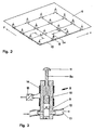
- Fig. 2: eine Schrägsicht auf eine hydraulische Ausführung;
- Fig. 3: einen Querschnitt durch ein Zylinder/Kolben-Element.
- Eine mechanische Ausführung der erfindungsgemässen Vorrichtung besteht gemäss Fig. 1 aus einem System von Auflagebalken 1, Querbalken 2, Grundbalken 3 und einem Verbindungsbalken 4. Sämtliche Auflagebalken 1 sind parallel zueinander sowie parallel zu den Grundbalken 3 angeordnet. Die Auflagebalken 1 sind paarweise über je einen Querbalken 2 und diese wiederum paarweise über je einen Grundbalken 3 verbunden. Der Verbindungsbalken 4 liegt zwischen den beiden Grundbalken 3. Die Querbalken 2 und der Verbindungsbalken 4 stehen hierbei rechtwinklig zu den Auflagebalken 1 und den Grundbalken 3. Die Stosstellen zwischen den rechtwinklig aufeinandertreffenden Balken liegen jeweils in der Balkenmitte und jeder Balken ist um die Längsachse a des anstossenden Balkens frei drehbar. An beiden Enden der Auflagebalken 1 sind vertikal nach oben gerichtete Stützträger 5 festgelegt, deren freie Enden Auflagepunkte für einen plattenförmigen Körper 6 bilden. Die Balkenlängen sind derart aufeinander abgestimmt, dass die Abstände lx und ly benachbarter Stützträger 5 in den beiden Balkenrichtungen x und y jeweils gleich sind.
- Damit das System bei aufgelegtem plattenförmigen Körper 6 eine stabile und im wesentlichen horizontale Lage einnimmt, ist gemäss Fig. 1 einer der Grundbalken 3 sowie der Verbindungsbalken 4 durch Träger 7 gegenüber einer feststehenden Unterlage horizontal abgestützt und demzufolge die freie Drehbarkeit des einen Grundbalkens 3 am Verbindungsbalken 4 aufgehoben. Weiterhin ist zur horizontalen Stabilisierung des Balkensystems vorgesehen, dass - - in der Zeichnung nicht dargestellt - - die Aufhängung der Balken, insbesondere der Auflagebalken 1 und der Querbalken 2, leicht über deren Schwerpunkt liegt. Damit ist sichergestellt, dass die Stützträger 5 vor dem Auflegen des plattenförmigen Körpers 6 bereits die richtige Lage einnehmen, d.h. nach oben gerichtet sind.
- Eine hydraulische Ausführung der erfindungsgemässen Vorrichtung besteht gemäss Fig. 2 aus einer regelmässigen Anordnung von gegenüber einer horizontalen Unterlage senkrecht stehenden Zylinder/Kolben-Elementen 8. Wie insbesondere auch aus Fig. 3 hervorgeht, besteht jedes Zylinder/Kolben-Element 8 aus einem Zylinder 9 - - beispielsweise aus Kunststoff - - und einem z.B. aus Stahl gefertigten Kolben 10 mit aufgesetztem Stützträger 5a. Am freien Ende des Stützträgers 5a sitzt ein gerundeter Auflagekopf 11 aus einem gleitfähigen Kunststoff, beispielsweise Teflon. Die als Auflagepunkte für den plattenförmigen Körper 6 dienenden Auflageköpfe 11 bilden insgesamt ein Rechteckmuster mit in den Hauptachsenrichtungen x und y gleichen Abständen lx und ly. Die Zylinder 9, die im übrigen alle denselben Innendurchmesser d aufweisen, sind über festwandige Schläuche 12 untereinander verbunden und bilden ein mit Hydraulikflüssigkeit 13 gefülltes, geschlossenes System. In Fig. 3 ist im weiteren eine Einrichtung 14, 15 angedeutet, welche die Vertikalverschiebung des Kolbens 10 zur Messung der Position des Auflagekopfes 11 in ein elektrisches Signal umwandelt. Zur horizontalen Stabilisierung des Systems bei aufgelegtem plattenförmigen Körper 6 sind - - in der Zeichnung nicht dargestellt - - jeweils zwei Kolben 10 arretierbar ausgebildet.
Claims (6)
dass die Unterlage aus einer Vielzahl von regelmässig angeordneten und dem plattenförmigen Körper (6) über jeweils eine im wesentlichen punktförmige Auflagefläche anliegenden, vertikal bewegbaren Stützträgern (5, 5a) besteht, wobei die Stützträger (5, 5a) mechanisch, hydraulisch oder pneumatisch untereinander derart verbunden sind, dass von jedem Stützträger (5, 5a) im wesentlichen dieselbe Kraft auf den plattenförmigen Körper (6) übertragen wird.
Priority Applications (1)
| Application Number | Priority Date | Filing Date | Title |
|---|---|---|---|
| AT88810746T ATE67587T1 (de) | 1987-11-06 | 1988-11-03 | Vorrichtung zum bestimmen der planheit eines plattenfoermigen koerpers. |
Applications Claiming Priority (2)
| Application Number | Priority Date | Filing Date | Title |
|---|---|---|---|
| CH435087 | 1987-11-06 | ||
| CH4350/87 | 1987-11-06 |
Publications (2)
| Publication Number | Publication Date |
|---|---|
| EP0317502A1 EP0317502A1 (de) | 1989-05-24 |
| EP0317502B1 true EP0317502B1 (de) | 1991-09-18 |
Family
ID=4274463
Family Applications (1)
| Application Number | Title | Priority Date | Filing Date |
|---|---|---|---|
| EP88810746A Expired - Lifetime EP0317502B1 (de) | 1987-11-06 | 1988-11-03 | Vorrichtung zum Bestimmen der Planheit eines plattenförmigen Körpers |
Country Status (5)
| Country | Link |
|---|---|
| EP (1) | EP0317502B1 (de) |
| AT (1) | ATE67587T1 (de) |
| DE (1) | DE3864983D1 (de) |
| ES (1) | ES2026275T3 (de) |
| GR (1) | GR3002748T3 (de) |
Families Citing this family (3)
| Publication number | Priority date | Publication date | Assignee | Title |
|---|---|---|---|---|
| IT1280989B1 (it) * | 1995-10-20 | 1998-02-11 | Dea Spa | Calibro per il collaudo dimensionale di pezzi. |
| CN111561861A (zh) * | 2020-06-30 | 2020-08-21 | 张长勤 | 一种建筑工程地面平整度测量装置 |
| CN114453988A (zh) * | 2022-01-19 | 2022-05-10 | 安徽强龙工业有限公司 | 智能平面磨 |
Family Cites Families (5)
| Publication number | Priority date | Publication date | Assignee | Title |
|---|---|---|---|---|
| BE756176A (fr) * | 1969-09-17 | 1971-03-15 | Ppg Industries Inc | Procede et appareil pour determiner le profil d'objets, d'objets en verre en particulier |
| DE2434603A1 (de) * | 1974-07-18 | 1976-01-29 | Waldmann Geb Sirp Hiltraud | Vorrichtung zur kontrolle der massund formgenauigkeit, insbesondere plattenfoermiger gegenstaende |
| US4221053A (en) * | 1978-11-13 | 1980-09-09 | Libbey-Owens-Ford Company | Inspection apparatus |
| DE3121579C2 (de) * | 1981-05-30 | 1983-07-14 | Daimler-Benz Ag, 7000 Stuttgart | In den drei Raumrichtungen messende Meßtasteinrichtung für Meßlehren |
| EP0125330A1 (de) * | 1983-05-16 | 1984-11-21 | The Boeing Company | Prüfungsanordnung für Aussenhautkonturen |
-
1988
- 1988-11-03 EP EP88810746A patent/EP0317502B1/de not_active Expired - Lifetime
- 1988-11-03 ES ES198888810746T patent/ES2026275T3/es not_active Expired - Lifetime
- 1988-11-03 DE DE8888810746T patent/DE3864983D1/de not_active Expired - Lifetime
- 1988-11-03 AT AT88810746T patent/ATE67587T1/de not_active IP Right Cessation
-
1991
- 1991-09-19 GR GR91401271T patent/GR3002748T3/el unknown
Also Published As
| Publication number | Publication date |
|---|---|
| DE3864983D1 (de) | 1991-10-24 |
| GR3002748T3 (en) | 1993-01-25 |
| ATE67587T1 (de) | 1991-10-15 |
| ES2026275T3 (es) | 1992-04-16 |
| EP0317502A1 (de) | 1989-05-24 |
Similar Documents
| Publication | Publication Date | Title |
|---|---|---|
| DE69117165T2 (de) | Verfahren zum Erfassen der Geradheit von Aufzugsschienen und zum Geradebiegen der Schiene und eine Vorrichtungskombination zur Durchführung des Verfahrens | |
| DE4313719C2 (de) | Transportvorrichtung | |
| DE3324519C2 (de) | ||
| DE2624647C2 (de) | Vorrichtung zum Messen der auf ein Meßobjekt wirkenden Kräfte und Momente eines strömenden Mediums | |
| DE2752319A1 (de) | Vorrichtung zum erkennen einer evtl. verformung eines bestimmten gestells oder aufbaus, wie einem fahrgestell oder einer selbsttragenden karosserie eines kraftfahrzeuges | |
| DE2945846A1 (de) | Vorrichtung zur pruefung der oberflaechenform von scheibenfoermigen materialien, vorzugsweise gebogenen glasscheiben | |
| DE202023103839U1 (de) | Bohrerführungsvorrichtung für Handbohrmaschine | |
| DE3532654C2 (de) | ||
| EP0483939B1 (de) | Ausrichten von Horizontalwalzen | |
| EP2112458B1 (de) | Verfahren und Vorrichtung zur Prüfung der Maßgenauigkeiten von Trommelbremsbelägen | |
| CH667916A5 (de) | Verfahren und mess-richtgeraet zur messung der geradheit und ebenheit. | |
| EP0317502A1 (de) | Vorrichtung zum Bestimmen der Planheit eines plattenförmigen Körpers | |
| DE2430013A1 (de) | Verfahren zum ablehren von kupplungskoerpern der automatischen mittelpufferkupplung fuer schienenfahrzeuge und vorrichtung zur durchfuehrung des verfahrens | |
| DE3723475C2 (de) | Vorrichtung zum Einspannen von Materialproben in Prüfmaschinen | |
| DE3439191A1 (de) | Pressvorrichtung mit gewichten fuer die herstellung von kaese | |
| DE202023102826U1 (de) | Eine Vorrichtung zur präzisen Positionierung von Hochgeschwindigkeits-Magnetschwebebahngleisträgern während des Anlagenbauprozesses | |
| DE3824575A1 (de) | Anlage mit mindestens einem aus zwei parallelen schienen bestehenden gleis zum radsatz- bzw. fahrgestellwechsel | |
| DE2532675A1 (de) | Messmethode fuer ein lager | |
| EP0766075B1 (de) | Verfahren zur gleichzeitigen Prüfung von mehreren Kraftaufnehmern, insbesondere Wägezellen, mit einer Drucklast | |
| DE3427701C2 (de) | ||
| DE3121373A1 (de) | Geraet zum insbesondere dreidimensionalen messen und/oder anreissen und/oder antasten von werkstuecken | |
| DE3942452A1 (de) | Ermittlung der federkennlinie eines vor- und fertiggeruestes | |
| DE4208261C1 (en) | Method of operating laminate board press - uses upper and lower press plates with cross beams and controllable piston cylinder actuators | |
| DE3100949C2 (de) | Vorrichtung zum Wägen von Transportfahrzeugen während der Fahrt | |
| DE1658302C (de) | Vorrichtung zum Anheben von Gleisen |
Legal Events
| Date | Code | Title | Description |
|---|---|---|---|
| PUAI | Public reference made under article 153(3) epc to a published international application that has entered the european phase |
Free format text: ORIGINAL CODE: 0009012 |
|
| AK | Designated contracting states |
Kind code of ref document: A1 Designated state(s): AT BE CH DE ES FR GB GR IT LI LU NL SE |
|
| 17P | Request for examination filed |
Effective date: 19891018 |
|
| RAP1 | Party data changed (applicant data changed or rights of an application transferred) |
Owner name: ALUSUISSE-LONZA SERVICES AG |
|
| 17Q | First examination report despatched |
Effective date: 19901211 |
|
| ITF | It: translation for a ep patent filed | ||
| GRAA | (expected) grant |
Free format text: ORIGINAL CODE: 0009210 |
|
| AK | Designated contracting states |
Kind code of ref document: B1 Designated state(s): AT BE CH DE ES FR GB GR IT LI LU NL SE |
|
| REF | Corresponds to: |
Ref document number: 67587 Country of ref document: AT Date of ref document: 19911015 Kind code of ref document: T |
|
| PGFP | Annual fee paid to national office [announced via postgrant information from national office to epo] |
Ref country code: FR Payment date: 19911011 Year of fee payment: 4 Ref country code: CH Payment date: 19911011 Year of fee payment: 4 |
|
| PGFP | Annual fee paid to national office [announced via postgrant information from national office to epo] |
Ref country code: SE Payment date: 19911016 Year of fee payment: 4 Ref country code: DE Payment date: 19911016 Year of fee payment: 4 |
|
| PGFP | Annual fee paid to national office [announced via postgrant information from national office to epo] |
Ref country code: AT Payment date: 19911017 Year of fee payment: 4 |
|
| PGFP | Annual fee paid to national office [announced via postgrant information from national office to epo] |
Ref country code: LU Payment date: 19911018 Year of fee payment: 4 |
|
| REF | Corresponds to: |
Ref document number: 3864983 Country of ref document: DE Date of ref document: 19911024 |
|
| PGFP | Annual fee paid to national office [announced via postgrant information from national office to epo] |
Ref country code: GR Payment date: 19911031 Year of fee payment: 4 |
|
| PGFP | Annual fee paid to national office [announced via postgrant information from national office to epo] |
Ref country code: ES Payment date: 19911106 Year of fee payment: 4 |
|
| PGFP | Annual fee paid to national office [announced via postgrant information from national office to epo] |
Ref country code: BE Payment date: 19911120 Year of fee payment: 4 |
|
| ET | Fr: translation filed | ||
| PGFP | Annual fee paid to national office [announced via postgrant information from national office to epo] |
Ref country code: NL Payment date: 19911130 Year of fee payment: 4 |
|
| GBT | Gb: translation of ep patent filed (gb section 77(6)(a)/1977) | ||
| EPTA | Lu: last paid annual fee | ||
| REG | Reference to a national code |
Ref country code: ES Ref legal event code: FG2A Ref document number: 2026275 Country of ref document: ES Kind code of ref document: T3 |
|
| PLBE | No opposition filed within time limit |
Free format text: ORIGINAL CODE: 0009261 |
|
| STAA | Information on the status of an ep patent application or granted ep patent |
Free format text: STATUS: NO OPPOSITION FILED WITHIN TIME LIMIT |
|
| 26N | No opposition filed | ||
| REG | Reference to a national code |
Ref country code: GR Ref legal event code: FG4A Free format text: 3002748 |
|
| PG25 | Lapsed in a contracting state [announced via postgrant information from national office to epo] |
Ref country code: LU Free format text: LAPSE BECAUSE OF NON-PAYMENT OF DUE FEES Effective date: 19921103 Ref country code: GB Effective date: 19921103 Ref country code: AT Effective date: 19921103 |
|
| PG25 | Lapsed in a contracting state [announced via postgrant information from national office to epo] |
Ref country code: SE Effective date: 19921104 Ref country code: ES Free format text: LAPSE BECAUSE OF NON-PAYMENT OF DUE FEES Effective date: 19921104 |
|
| PG25 | Lapsed in a contracting state [announced via postgrant information from national office to epo] |
Ref country code: LI Effective date: 19921130 Ref country code: CH Effective date: 19921130 Ref country code: BE Effective date: 19921130 |
|
| BERE | Be: lapsed |
Owner name: ALUSUISSE-LONZA SERVICES A.G. Effective date: 19921130 |
|
| PG25 | Lapsed in a contracting state [announced via postgrant information from national office to epo] |
Ref country code: GR Free format text: THE PATENT HAS BEEN ANNULLED BY A DECISION OF A NATIONAL AUTHORITY Effective date: 19930531 |
|
| PG25 | Lapsed in a contracting state [announced via postgrant information from national office to epo] |
Ref country code: NL Effective date: 19930601 |
|
| GBPC | Gb: european patent ceased through non-payment of renewal fee |
Effective date: 19921103 |
|
| NLV4 | Nl: lapsed or anulled due to non-payment of the annual fee | ||
| PG25 | Lapsed in a contracting state [announced via postgrant information from national office to epo] |
Ref country code: FR Effective date: 19930730 |
|
| REG | Reference to a national code |
Ref country code: CH Ref legal event code: PL |
|
| PG25 | Lapsed in a contracting state [announced via postgrant information from national office to epo] |
Ref country code: DE Effective date: 19930803 |
|
| REG | Reference to a national code |
Ref country code: FR Ref legal event code: ST |
|
| REG | Reference to a national code |
Ref country code: GR Ref legal event code: MM2A Free format text: 3002748 |
|
| EUG | Se: european patent has lapsed |
Ref document number: 88810746.3 Effective date: 19930610 |
|
| REG | Reference to a national code |
Ref country code: ES Ref legal event code: FD2A Effective date: 19931214 |
|
| PG25 | Lapsed in a contracting state [announced via postgrant information from national office to epo] |
Ref country code: IT Free format text: LAPSE BECAUSE OF NON-PAYMENT OF DUE FEES;WARNING: LAPSES OF ITALIAN PATENTS WITH EFFECTIVE DATE BEFORE 2007 MAY HAVE OCCURRED AT ANY TIME BEFORE 2007. THE CORRECT EFFECTIVE DATE MAY BE DIFFERENT FROM THE ONE RECORDED. Effective date: 20051103 |