EP0316954B1 - Méthode de reproduction pour enregistreur à bande du genre à téte rotative - Google Patents
Méthode de reproduction pour enregistreur à bande du genre à téte rotative Download PDFInfo
- Publication number
- EP0316954B1 EP0316954B1 EP88119245A EP88119245A EP0316954B1 EP 0316954 B1 EP0316954 B1 EP 0316954B1 EP 88119245 A EP88119245 A EP 88119245A EP 88119245 A EP88119245 A EP 88119245A EP 0316954 B1 EP0316954 B1 EP 0316954B1
- Authority
- EP
- European Patent Office
- Prior art keywords
- signal
- track
- trace
- tracks
- sampling
- Prior art date
- Legal status (The legal status is an assumption and is not a legal conclusion. Google has not performed a legal analysis and makes no representation as to the accuracy of the status listed.)
- Expired - Lifetime
Links
Images


Classifications
-
- G—PHYSICS
- G11—INFORMATION STORAGE
- G11B—INFORMATION STORAGE BASED ON RELATIVE MOVEMENT BETWEEN RECORD CARRIER AND TRANSDUCER
- G11B15/00—Driving, starting or stopping record carriers of filamentary or web form; Driving both such record carriers and heads; Guiding such record carriers or containers therefor; Control thereof; Control of operating function
- G11B15/18—Driving; Starting; Stopping; Arrangements for control or regulation thereof
- G11B15/46—Controlling, regulating, or indicating speed
- G11B15/467—Controlling, regulating, or indicating speed in arrangements for recording or reproducing wherein both record carriers and heads are driven
-
- G—PHYSICS
- G11—INFORMATION STORAGE
- G11B—INFORMATION STORAGE BASED ON RELATIVE MOVEMENT BETWEEN RECORD CARRIER AND TRANSDUCER
- G11B15/00—Driving, starting or stopping record carriers of filamentary or web form; Driving both such record carriers and heads; Guiding such record carriers or containers therefor; Control thereof; Control of operating function
- G11B15/18—Driving; Starting; Stopping; Arrangements for control or regulation thereof
- G11B15/1808—Driving of both record carrier and head
- G11B15/1875—Driving of both record carrier and head adaptations for special effects or editing
-
- G—PHYSICS
- G11—INFORMATION STORAGE
- G11B—INFORMATION STORAGE BASED ON RELATIVE MOVEMENT BETWEEN RECORD CARRIER AND TRANSDUCER
- G11B15/00—Driving, starting or stopping record carriers of filamentary or web form; Driving both such record carriers and heads; Guiding such record carriers or containers therefor; Control thereof; Control of operating function
- G11B15/18—Driving; Starting; Stopping; Arrangements for control or regulation thereof
- G11B15/46—Controlling, regulating, or indicating speed
- G11B15/467—Controlling, regulating, or indicating speed in arrangements for recording or reproducing wherein both record carriers and heads are driven
- G11B15/4673—Controlling, regulating, or indicating speed in arrangements for recording or reproducing wherein both record carriers and heads are driven by controlling the speed of the tape while the head is rotating
- G11B15/4675—Controlling, regulating, or indicating speed in arrangements for recording or reproducing wherein both record carriers and heads are driven by controlling the speed of the tape while the head is rotating with provision for information tracking
- G11B15/4676—Controlling, regulating, or indicating speed in arrangements for recording or reproducing wherein both record carriers and heads are driven by controlling the speed of the tape while the head is rotating with provision for information tracking using signals recorded in tracks disposed in parallel with the scanning direction
- G11B15/4677—Controlling, regulating, or indicating speed in arrangements for recording or reproducing wherein both record carriers and heads are driven by controlling the speed of the tape while the head is rotating with provision for information tracking using signals recorded in tracks disposed in parallel with the scanning direction using auxiliary signals, i.e. pilot signals
- G11B15/4678—Controlling, regulating, or indicating speed in arrangements for recording or reproducing wherein both record carriers and heads are driven by controlling the speed of the tape while the head is rotating with provision for information tracking using signals recorded in tracks disposed in parallel with the scanning direction using auxiliary signals, i.e. pilot signals superimposed on the main signal track
Definitions
- the present invention relates to a method of reproducing for a tape recorder of the rotary head type such as a digital audio tape recorder of the rotary head type in which the reproduction tracking is controlled by an area division type ATF (Automatic Track Finding) method. More particularly, the present invention relates to a method of reproducing a magnetic tape in which sounds, images and the like have been digitally recorded at a speed equal to a half of the normal tape speed.
- ATF Automatic Track Finding
- the rotary head type digital audio tape recorder of the type above-mentioned (hereinafter referred to as the R-DAT), there is known, for example, an audio tape recorder as shown in "Technology of Television - Serial No. 427", a monthly magazine published by Denshi Gijyutsu Syuppan Co., Ltd., in April, 1987, Pages 109 to 117 and in "Electronics Life”, a monthly magazine published by Nippon Housou Shuppan Kyoukai in March 1987, Pages 11 to 66 and in Proceedings of the International Congress on Transportation Electronics, October 1986, Warrendale, M. Finer : “Sony Digital Audio Tape (DAT)", pages 321-331.
- DAT Nony Digital Audio Tape
- a pair of rotary magnetic heads each having plus or minus azimuth are disposed at the rotary drum (head cylinder), as separated from each other by 180° on the periphery of the rotary drum.
- the rotary magnetic heads helically scan a magnetic tape travelling as wound on the drum at 90°.
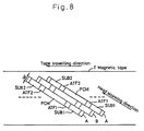
- the heads successively generate, on the tape in a guard bandless manner, tracks A and B in which digital audio signals (PCM audio signals), tracking control ATF signals and the like have been recorded in an area division format shown in Fig. 8.
- Each of the tracks A and B has each of the azimuths of the pair of heads.
- the tracks are overlappingly recorded and generated such that each track has a width equal to 2/3 of the width of each head.
- Each of the tracks A and B consits of 196 blocks, each having a 288-bit signal length. From the trace starting end, each track is successively time-divided into a first sub code area SUB1, a first ATF area ATF1, a PCM area PCM, a second ATF area ATF2 and a second sub code area SUB2.
- PCM audio signals are recorded in the PCM area PCM, and search signals, time signals and the like relating to the PCM audio signals are recorded, as sub information, in the first and second sub code areas SUB1 and SUB2.
- ATF signals required for tracking control at the time of reproduction such as synchronizing signals and pilot signals, are recorded in the first ATF area ATF1 at the starting end and the second ATF area ATF2 at the terminal end, in a format of the 4-track completion type (to be discussed later).
- Each of the first ATF area ATF1 and the second ATF area ATF 2 has a five-block length.
- the following signals are recorded, as the ATF signals, in time division in a pattern repeated at the period of four tracks in which the recording length and the recording order are changed;
- each signal five types of 0.5 ⁇ , 1 ⁇ , 1.5 ⁇ , 2 ⁇ , and 2.5 ⁇ are available where the length of one block is defined as 1 ⁇ .
- an f3 synchronizing signal, an erasion signal and a pilot signal are successively recorded in the first track B0 at the area ATF1 thereof from the trace starting end, these signals respectively having recording lengths of 1 ⁇ , 2 ⁇ and 2 ⁇ .
- a pilot signal, an erasion signal, an f3 synchronizing signal and an erasion signal are successively recorded in the first track B0 at the area ATF2 thereof from the trace starting end, these signals respectively having recording lengths of 2 ⁇ , 1 ⁇ , 1 ⁇ and 1 ⁇ .
- a pilot signal, an erasion signal, an f2 synchronizing signal and an erasion signal are successively recorded in the second track A1 at the area ATF1 thereof from the trace starting end, these signals respectively having recording lengths of 2 ⁇ , 1 ⁇ , 0.5 ⁇ and 1.5 ⁇ .
- An f2 synchronizing signal, an erasion signal and a pilot signal are successively recorded in the second track A1 at the area ATF2 thereof from the trace starting end, these signals respectively having recording lengths of 0.5 ⁇ , 2.5 ⁇ and 2 ⁇ .
- An f3 synchronizing signal, an erasion signal and a pilot signal are successively recorded in the third track B1 at the area ATF1 thereof from the trace starting end, these signals respectively having recording lengths of 0.5 ⁇ , 2.5 ⁇ and 2 ⁇ .
- a pilot signal, an erasion signal, an f3 synchronizing signal and an erasion signal are successively recorded in the third track B1 at the area ATF2 thereof from the trace starting end, these signals respectively having recording lengths of 2 ⁇ , 1 ⁇ , 0.5 ⁇ and 1.5 ⁇ .
- a pilot signal, an erasion signal, an f2 synchronizing signal and an erasion signal are successively recorded in the fourth track A2 at the area ATF1 thereof from the trace starting end, these signals respectively having recording lengths of 2 ⁇ , 1 ⁇ , 1 ⁇ and 1 ⁇ .
- An f2 synchronizing signal, an erasion signal and a pilot signal are successively recorded in the fourth track A2 at the area ATF2 thereof from the trace starting end, these signals respectively having recording lengths of 1 ⁇ , 2 ⁇ . and 2 ⁇ .
- the areas ATF1 and ATF2 thereof have the same recording patterns to those of the areas ATF1 and ATF2 of the first track B0, respectively.
- a margin gap IBG having a length of 3 ⁇ is disposed between the area ATF1 and the PCM area PCM and between the area ATF2 and the PCM area PCM.
- a head trace is controlled by tracking control discussed in the following.
- the head gap width is 1.5 time the width of each of the tracks A and B. Accordingly, a reproduced signal from each head generally includes a signal component of the trace track and crosstalk components from two tracks adjacent to the trace track.
- the levels of both crosstalk components vary with the trace position. When the head center coincides with the track center to provide an on-track position, the levels of both crosstalk components are equal to each other.
- RFSW signal head changeover pulse signal
- the crosstalk components of the pilot signals of adjacent two tracks are sampled and extracted based on:
- a difference in level between both crosstalk components is then operated, thereby to generate a tracking control signal, i.e., a tracking error signal which is proportional to the level difference.
- the level of the tracking error signal varies with a shift in trace position between both heads. Accordingly, based on the tracking error signal, the tape T is controlled in travelling phase such that both heads are brought to the on-track position, thereby to control the head traces.
- a tape is normally recorded and reproduced with the tape travelling speed and the drum revolution speed respectively set to the standard travelling speed 8,150 mm/sec. and the standard revolution speed 2,000 r.p.m in the standard mode.
- the tape may be recorded in a double period of time with the tape travelling speed and the drum revolution speed respectively lowered to 4,075 mm/sec. i.e., a half of the standard travelling speed and to 1,000 r.p.m. i.e., a half of the standard revolution speed.
- the tape recorded in the long-time mode may be reproduced with the tape travelling speed set to 4,075 mm/sec, i.e., the same travelling speed as that used at the recording time.
- the drum revolution speed at the reproduction time is to be also set to the speed determined for the long-time mode used at the time of recording.
- the tape/head relative speed is lowered to 1/2 of that in the standard mode and the frequency of the reproduced signal from each head is also lowered to 1/2 of that in the standard mode.
- an electromagnetic conversion processing, a reproduction equalizer processing and the like may not be executed in the best conditions at the time of reproduction in the long-time mode.
- the drum revolution speed at the reproduction time is double the speed used at the recording time. Accordingly, each head scans the tape at a speed double the speed determined for the long-time mode, and the tape is repeatedly scanned substantially at the same position thereof by both heads. That is, the tape is reproduced by a so-called double scanning method.
- the tracking control is not made, but based on the detection of an error in a reproduced signal, a reproduction processing is made by selecting a reproduced PCM audio signal and a PCM signal as sub information which are less erroneous.
- EP-A-259195 is a document under article 54 (3) EPC and disclosures ATF tracking by a double scanning method.
- the tracking control of the rotary head bases on a reproduced tracking reference signal obtained in an ending portion one recording track in a first scan and a reproduced tracking reference signal obtained in a beginning portion of the following recording track in a second scan.
- the present invention provides a method of reproducing for a rotary head type tape recorder having the steps of: helically scanning a magnetic tape travelling as wound on a rotary drum at a predetermined angle by a pair of rotary magnetic heads each having plus or minus azimuth, the rotary magnetic heads disposed on the rotary drum as separated from each other by 180° at the peripheral edge of the drum; successively generating tracks on the magnetic tape in a guard bandless manner, each track having a width narrower than the gap width of each head; forming ATF areas on each of the tracks at the starting and terminal ends thereof, in each of which at least (i) a synchronizing signal as a sampling reference signal and (ii) a pilot signal as a tracking signal are recorded in a pattern repeated for a few tracks in which the signal frequency and recording length are changed; sampling, at the time of reproduction, crosstalk components of the pilot signals from two tracks adjacent to a trace track, based on detection of each of the synchronizing signals of the trace track at the starting and terminal ends thereof;
- the method of reproducing a rotary head type tape recorder in accordance with the present invention is characterized in that: when reproducing a magnetic tape which has been recorded in the long-time mode in which the tape travelling speed and the drum revolution speed are respectively set to a half of the standard travelling speed and to a half of the standard revolution speed, the tape travelling speed is set to a half of the standard travelling speed and the drum revolution speed is set to the standard revolution speed; and that for every continuous four traces, the sampling operation is stopped for the ATF area of the second trace at the terminal end thereof and the sampling operation is also stopped for the remaining continuous two traces.
- the rotary drum when reproducing a tape in the long-time mode, the rotary drum is rotated at the standard revolution speed to reproduce the tape by a double scanning method.
- the heads trace or scan the tape at a speed double the revolution speed determined for the long-time mode. Accordingly, in this case the trace position is moved in a widthwise direction by a distance corresponding to 1/2 of the track width as compared with the trace position at the time of standard reproduction with the use of the standard travelling speed and the standard revolution speed.
- the head scanning direction is inclined, at an extremely small angle, toward the preceding trace with respect to the track direction.
- the sampling operation is stopped for the ATF area of the succeeding trace at the terminal end thereof, as well as for the next continuous two traces. Accordingly, for every two traces, the sampling operation is made for the ATF areas of the preceding trace at the starting and terminal ends thereof and for the ATF area of the succeeding trace at starting end thereof. Based on the sampling results, the direction in which each head is brought to the on-track position at the starting end of the succeeding trace, is opposite to the direction in which each head is brought to the on-track position at the terminal end of the preceding trace.
- each head may be controlled such that it is brought substantially to the on-track position.
- a high-precision tracking control may be achieved by the double scanning method, thereby to assure a good reproduction.
- a reproduction input terminal 1 is adapted to receive a reproduced signal from each rotary magnetic head through a rotary transformer and a head changeover switch.
- a reproduction amplifier 2 is connected to the input terminal 1.
- a low-pass filter 3 for extracting a pilot signal is connected to the amplifier 2.
- An envelope detector circuit 4 is connected to the filter 3.
- a first sampling and holding circuit 5 is connected to the detector circuit 4 for sampling an input signal by a sampling pulse SPl.
- a subtracter 6 comprising a differential amplifier is adapted to operate a difference in level between a holding signal of the sampling and holding circuit 5 and an output signal of the detector circuit 4.
- a second sampling and holding circuit 7 is connected to the subtracter 6 for sampling an input signal by a sampling pulse SP2.
- the second sampling and holding circuit 7 is adapted to sample an input signal.
- a tracking control signal i.e., a tracking error signal for controlling the tape travelling phase
- an output signal of the second sampling and holding circuit 7 is supplied from a control output terminal 8 to a capstan motor drive circuit.
- a reproduction equalizer 9 is connected to the amplifier 2 for equalizing waveforms.
- a digital conversion comparator 10 comprising a zero cross comparator is adapted to convert an output signal from the equalizer circuit 9, into a binary value.
- a logic control circuit 11 comprising a microcomputer and the like, is connected to the comparator 10 for generating a sampling pulse.
- the logic control circuit 11 is adapted to detect, in a digital manner, that a synchronizing signal has been reproduced by an output signal of the comparator 10. Such detection is made based on a head changeover pulse signal of an RFSW input terminal 12, i.e., an RFSW signal, and based on a clock signal as an operation reference signal of the R-DAT.
- the control circuit 11 is adapted to carry out a timer operation to calculate the timings at which the pilot signals from adjacent two tracks are crosstalked. In such timings, the sampling pulses SP1 and SP2 are respectively generated and supplied.
- a gate circuit 13 is connected to the control circuit 11 for selectively supplying, at the time of reproduction in the long-time mode, the sampling pulses SP1 and SP2 to the sampling and holding circuits 5 and 7, respectively, based on the RFSW signal from the input terminal 12 and a reproduction mode signal.
- a reproduced signal from each head is supplied to the amplifier 2 through the input terminal 1.
- the reproduced signal thus amplified is entered into the filter 3 and the equalizer circuit 9.
- the filter 3 removes that component of the reproduced signal of which frequency is higher than that of the pilot signal, and extracts only a component having frequency substantially equal to the frequency of the pilot signal (hereinafter referred to as a pilot component).
- the pilot component thus extracted is supplied from the filter 3 to the detector circuit 4.
- the detector circuit 4 When the detector circuit 4 carries out an envelope detection, the detector circuit 4 supplies, to the sampling and holding circuit 5 and the subtracter 6, an envelope detection signal having the pilot component of the reproduced signal.
- the reproduced signal equalized in waveform by the equalizer circuit 9 is supplied to the comparator 10 which, in turn, converts the reproduced signal into a digitalized binary value.
- the comparator 10 supplies, as an output signal, a digital signal based on a signal component of which level considerably varies, i.e. a trace track signal component included in the reproduced signal.
- the digital signal from the comparator 10 is supplied to the control circuit 11.
- the control circuit 11 detects a synchronizing pattern
- the digital signal from the comparator 10 is sampled at intervals of a clock signal which has frequency of 9,408 MHz and serves as an operation reference signal.
- the control circuit 11 When the control circuit 11 carries out a track identification, it is estimated which track is the next trace track to be switched by the RFSW signal, out of four tracks, for example, A1, B1, A2 and B2 of the four-track completion type as shown in Fig. 9. While the synchronizing signal is being reproduced, the trace track is determined.
- the sampling pulses SP1 and SP2 are generated and supplied to the gate circuit 13 in timings that the pilot signals from the adjacent two tracks are crosstalked.
- the synchronizing signal of the area ATF2 has a length of 0.5 ⁇ in the tracks A1 and B1 in which the synchronizing signal of the area ATF1 has a length of 0.5 ⁇ .
- the synchronizing signal of the area ATF2 has a length of 1 ⁇ in the tracks A2 and B2 in which the synchronizing signal of the area ATF1 has a length of 1 ⁇ .
- an output signal from the detector circuit 4 has a pilot component crosstalked from one track out of the adjacent two tracks, i.e., the succeeding track to be scanned next to the trace track, the succeeding track being shown at the right hand with respect to each track in Fig. 9 (hereinafter referred to as the R-track).
- the output signal from the detector circuit 4 has a pilot component crosstalked from the other track of the adjacent two tracks, i.e., the preceding track scanned previously to the trace track, the preceding track being shown at the left hand with respect to each track in Fig. 9 (hereinafter referred to as the L-track).
- the control circuit 11 Upon start of generation of the synchronizing detection pulse, the control circuit 11 immediately starts generating the sampling pulse SP1 and counting the number of synchronizing detection pulses. It is judged whether or not the counted number of the synchronizing detection pulses reaches the value 0.5 ⁇ or 1 ⁇ previously set based on the estimation of trace track. Based on this judgment, it is judged whether or not the synchronizing signal has been reproduced. Then, the trace track is determined. After 2 has passed from the start of counting the synchronizing detection pulses, the sampling pulse SP2 is generated.
- control circuit 11 supplies the sampling pulses SP1 and SP2 to the gate circuit 13 in timings that the pilot components of the adjacent two tracks are crosstalked.
- the trace track is the track A2 in Fig. 9.
- a pilot signal having a length of 2 ⁇ is reproduced as a reproduced signal of the trace track A2.
- a synchronizing signal with frequency f2 having a length of 1 ⁇ is reproduced.
- the pilot signals from the R- and L-tracks B2 and B1 are crosstalked during and after the synchronizing signal of the trace track A2 is reproduced.
- the output signal from the detector circuit 4 varies as shown in Fig. 2 (b) in which Pm is the pilot signal of the trace track A2, and Pr and Pl are the pilot components crosstalked from the R- and L-tracks B2 and B1, respectively.
- the sampling pulses SP1 and SP2 are respectively supplied in timings shown in Fig. 2 (c) and (d).
- the gate circuit 13 When reproducing a tape in the standard mode, i.e., when reproducing the tape with the tape travelling speed and the drum revolution speed respectively set to the standard travelling speed and the standard drum revolution speed which are the same as those used at the recording time, the gate circuit 13 supplies the sampling pulses SP1 and SP2, as they are, to the sampling and holding circuits 5 and 7, respectively.
- the sampling and holding circuit 5 Based on the sampling pulse SP1 supplied to the sampling and holding circuit 5 through the gate circuit 13, the sampling and holding circuit 5 samples and holds the pilot component crosstalked from the R-track.
- the subtracter 6 subtracts the output signal of the sampling and holding circuit 5 from the output signal of the detector circuit 4.
- the subtracter 6 supplies an output signal proportional to a difference in level between the pilot components crosstalked from the adjacent two tracks.
- a tracking error signal supplied from the sampling and holding circuit 7 to the capstan motor drive circuit through the output terminal 8 is a signal having S-shape characteristics which is proportional to a difference in level between the pilot components crosstalked from the adjacent two tracks. Based on this tracking error signal, the tape travelling phase is controlled.
- the tape travelling speed and the drum revolution speed are the same as those used at the recording time. Accordingly, the head scanning direction extends along the track direction.
- the tape travelling phase is variably controlled such that the head center coincides with the track center.
- the pilot components crosstalked from the adjacent two tracks are equal to each other in level and the tracking error signal is 0 in level, the head center coincides with the track center, thus providing a complete on-track position.
- the tracking error signal varies, according to the tracking shift, in the form of the S-shape characteristics substantially proportional to the characteristics shown by the solid line in Fig. 7. Based on this error signal, each head is brought to the complete on-track position.
- the tape travelling speed is set to the travelling speed determined for the long-time mode which is the same as that used at the recording time
- the drum revolution speed is set to a speed double the drum revolution speed used at the recording time, i.e., a speed double the drum revolution speed determined for the long-time mode.
- each trace terminal end position on the tape is shifted in an extremely small amount in the advancement direction (the left hand in Fig. 9).
- the head scanning direction is angularly shifted in an extremely small amount with respect to the tracking direction, as shown in Figs. 3 and 4.
- the scanning amount is equal to only 1/2 of that in the standard mode. Accordingly, both heads double-scan each track.
- Figs. 3 and 4 show (i) tracks A and B which are successively formed, and (ii) head traces Ha1, Hb1, Ha2, Hb2 and Ha3, among which the head traces Ha1, Ha2 and Ha3 are the traces scanned by the head having the same azimuth as that of the track A, and the traces Hb1 and Hb2 are the traces scanned by the head having the same azimuth as that of the track B.
- the tape may be reproduced without switching the characteristics of the electromagnetic conversion system such as the heads and the rotary transformers, as well as the characteristics of the amplifier 2 and the equalizer circuit 9.
- the tracking control block shown in Fig. 1 is operated. At this time, since the drum revolution speed is higher than that used at the recording time, (i) the electromagnetic conversion, (ii) the amplification by the amplifier 2 and (iii) the equalization of waveforms by the equalizer circuit 9 are carried out with the characteristics substantially equal to those at the time of reproduction in the standard mode.
- the RFSW signal of the input terminal 12 shown in Fig. 5 (a), i.e, the RFSW signal having the same cycle as that at the reproduction in the standard mode, is supplied to the control circuit 11.
- the level of the RFSW signal is inverted, i.e., each time the rotary drum makes a half turn, the trace head is switched.
- the RFSW signal level inversion timing and the trace head changeover timing are the same as those in the reproduction in the standard mode.
- the control circuit 11 is operated in the same manner as in the reproduction in the standard mode.
- the control circuit 11 When the synchronizing signal of a trace track is reproduced for every scanning of each head, the control circuit 11 generates and supplies the sampling pulses SP1 and SP2 in the timings shown in Fig. 5 (b) and (c), respectively.
- each of the heads reproduces the tape for a period of time of each forward half portion of the high and low levels of the RFSW signal, i.e. for a period of time corresponding to a 90°-turn of the rotary drum.
- each of the heads scans the tape while moving by a distance of about 1/2 of the track width W for each trace, i.e., by a distance of about 1/2 of that moved at the time of the reproduction in the standard mode.
- the control circuit 11 does not supply the sampling pulses SP1 and SP2.
- the first trace Ha1 and the second trace Hb1, shown by the solid lines, out of the continuous four traces Ha1, Hb1, Ha2, Hb2, are the traces in which the heads have scanned, substantially in the on-track manner, the tracks A and B each having the same azimuth as that of each of the heads.
- the third trace Ha2 and the fourth trace Hb2, shown by the broken lines, are the traces in which each of the heads has scanned the track B or A having different azimuth from that of each of the heads.
- the first trace Ha1 and the fourth trace Hb2, shown by the solid lines, out of the continuous four traces Ha1, Hb1, Ha2, Hb2 are the traces in which the heads have scanned, substantially in the on-track manner, the tracks A and B each having the same azimuth as that of each of the heads.
- the second trace Hb1 and the third trace Ha2, shown by the broken lines, are the traces in which each of the heads has scanned the track B or A having different azimuth from that of each of the heads.
- the first trace Ha3 and the second trace are the traces in which the heads have scanned, substantially in the on-track manner, the tracks each having the same azimuth as that of each of the heads.
- the first trace and the fourth trace are the traces in which the heads have scanned, substantially in the on-track manner, the tracks each having the same azimuth as that of each of the heads.
- continuous two traces are the traces in which the heads have scanned, substantially in the on-track manner, the tracks each having the same azimuth as that of each of the heads, and the subsequent two traces are the traces in which each of the heads has scanned a track having different azimuth from that of each of the heads.
- the tracks A and B are scanned substantially in the on-track manner by the heads each having the same azimuth as that of each of the tracks.
- the heads each having the same azimuth as that of each of the tracks A and B are designated by HA and HB, respectively.
- the heads may be automatically brought to the trace positions as shown in Fig. 3, basically, by the following arrangement in which:
- the heads may be also automatically brought to the trace positions as shown in Fig. 4, basically, by the following arrangement in which:
- the heads may be brought to the trace positions shown in Fig. 3 and Fig. 4, by the following arrangement in which:
- the supply of the sampling pulses SP1 and SP2 from the gate circuit 13 may be inhibited for two traces Ha2 and Hb2 out of the continuous four traces Ha1, Hb1, Ha2 and Hb2, and the gate circuit 13 may supply the sampling pulses SP1 and SP2 for two traces Ha1 and Hb1.
- the sampling and holding circuits 5 and 7 sample the input signals for the two traces Ha1 and Hb1 and stops sampling the input signals for the two traces Ha2 and Hb2.
- the ATF areas ATF2 of the traces Ha1 and Hb1 at the terminal ends thereof are shifted left (to the preceding-trace side) with respect to the ATF areas ATF1 of the traces Ha1 and Hb1 at the starting ends thereof.
- the tracking error signals respectively supplied at the time when the ATF areas ATF1 and ATF2 of the trace Ha1 are scanned vary according to the characteristics respectively shown by broken lines ⁇ 1 and ⁇ 2 in Fig. 6.
- the tracking error signals respectively supplied at the time when the ATF areas ATF1 and ATF2 of the trace Hb1 are scanned vary according to the characteristics respectively shown by broken lines ⁇ 1 and ⁇ 2 in Fig. 6.
- the tracking control achieved by the error signals shown by the broken lines ⁇ 1 and ⁇ 2 has composite characteristics shown by an alternate long and short dash line ⁇ 12.
- the tracking control achieved by the error signals shown by the broken lines ⁇ 1 and ⁇ 2 has composite characteristics shown by an alternate long and short dash line ⁇ 12.
- the tracking control achieved by the error signals shown by the broken lines ⁇ 12 and ⁇ 12 has composite characteristics shown by the solid line in Fig. 6.
- the tracking positions are servo-controlled based on the tracking error signals shown by the broken lines ⁇ 1, ⁇ 2, ⁇ 1 and ⁇ 2.
- the tracking positions of the heads HA and HB are brought to the positions where the level of the error signal having the composite characteristics shown by the solid line in Fig. 6, reaches substantially zero, i.e., the positions substantially shown in Fig. 3.
- the gate circuit 13 may be inhibited from supplying the sampling pulses SP1 and SP2 for two traces Hb1 and Ha2 out of the continuous four traces Ha1, Hb1, Ha2 and Hb2.
- the tracking positions are servo-controlled based on the tracking error signals having the characteristics similar to those shown by the broken lines ⁇ 1, ⁇ 2, ⁇ 1 and ⁇ 2.
- the tracking positions of the heads HA and HB are brought to the positions substantially shown in Fig. 4.
- the tracking control is made based on the tracking error signal obtained by the immediately previous sampling operation, i.e.,
- the control made based on the tracking error signal obtained for the second ATF area ATF2 at the terminal end side of the succeeding trace is continued for a longer period of time than that of the control made based on the tracking error signals obtained for both ATF areas ATF1 and ATF2 of the preceding trace and the tracking error signal obtained for the first ATF area ATF1 at the starting end side of the preceding trace.
- the tracking control based on the tracking error signal obtained for the second ATF area ATF2 of the succeeding trace has the characteristics shown by the broken line ⁇ 2 in Fig. 6.
- the tracking control made based on the signal shown by the broken line ⁇ 2 produces a tracking shift greater than that in the tracking control made based on the tracking error signal obtained for the first ATF area ATF1 of the same trace, the last-mentioned tracking control having the characteristics substantially shown by the broken line ⁇ 1 in Fig. 6. Accordingly, the first-mentioned tracking control is apparently offset, and the general tracking characteristics deviate from the optimum characteristics passing through the original point as shown by the solid line in Fig. 6.
- the gate circuit 13 is inhibited from supplying the sampling pulse SP2 for the second ATF area ATF2 of the succeeding trace.
- the gate circuit 13 is inhibited from supplying:
- the gate circuit 13 supplies the sampling pulses SP1 and SP2 in the timings shown in Fig. 5 (d) and (e), respectively, and the sampling operation of a tracking error signal by the sampling and holding circuit 7 based on the sampling pulse SP2 is stopped for the second ATF area ATF2 of the trace Hb1 and for both ATF areas ATF1 and ATF2 of the traces Ha2 and Hb2.
- signals respectively shown by broken lines ⁇ 1′, ⁇ 2′, ⁇ 1′ and an alternate long and short dash line ⁇ 12′ are respectively corresponding to those shown by the broken lines ⁇ 1, ⁇ 2, ⁇ 1 and the alternate long and short dash line ⁇ 12 in Fig. 6.
- the general tracking control has optimum S-shape characteristics passing through the original point as shown by the solid line in Fig. 7. This enables to achieve a high-precision tracking control. Accordingly, the heads HA and HB are brought substantially to the on-track position one time for every two traces such that the tracks A and B are reproduced with a proper tracking control performed.
- the gate circuit 13 is inhibited from supplying the sampling pulse SP2 for the second ATF area ATF2 of the trace Ha1 and the sampling pulses SP1 and SP2 for the ATF areas ATF1 and ATF2 of two traces Hb1 and Ha2.
- a tracking control based on the tracking error signal shown by the broken line ⁇ 2 in Fig. 6, as mentioned earlier.
- a tracking control generally having the characteristics substantially the same as that shown by the solid line in Fig. 7. This achieves a high-precision tracking control when reproducing the tracks A and B.
- the gate circuit 13 is inhibited from supplying, for every continuous two traces of the heads HA and HB or for every continuous two traces of the heads HB and HA:
- a high-precision tracking control is made such that the heads HA and HB are brought to the tracking positions shown in Fig. 4 or Fig. 5. Accordingly, with a simple arrangement of adding the gate circuit 13, a good reproduction by the double scanning method may be achieved according to a high-precision tracking control.
- the tracking control is made based on the tracking error signals such that the other head capable of operating for reproduction is brought to the on-track position. This achieves a relatively good reproduction.
- the present invention may be applied to a method of reproducing a rotary head type tape recorder in which the reproduction tracking control is made according to the area division type ATF method of which format is different from that of the R-DAT.
- the travelling speed, the revolution speed and the like determined for the long-time mode may be different from those described in the embodiment above-mentioned.
Landscapes
- Engineering & Computer Science (AREA)
- Signal Processing (AREA)
- Adjustment Of The Magnetic Head Position Track Following On Tapes (AREA)
Claims (3)
- Procédé de reproduction pour un enregistreur à bande du type à tête rotative comprenant les étapes consistant à :
balayer en hélice une bande magnétique défilant à l'état enroulé sur un tambour rotatif sous un angle prédéterminé, par une paire de têtes magnétiques rotatives ayant chacune un azimut positif ou négatif, lesdites têtes magnétiques rotatives étant disposées sur ledit tambour rotatif en étant séparées l'une de l'autre par 180° sur la bordure périphérique dudit tambour :
engendrer successivement des pistes sans bande de garde sur ladite bande magnétique au moment de l'enregistrement, chacune desdites pistes ayant une largeur plus petite que la hauteur de l'entrefer (W) de chacune desdites têtes ;
réaliser des zones de recherche automatique de piste "ATF" (ATF1, ATF2) sur chacune desdites pistes à leurs extrémités initiales et finales, dans chacune desquelles au moins (i) un signal de synchronisation (f2, f3) en tant que signal de référence d'échantillonnage et (ii) un signal pilote (f1) en tant que signal de pistage sont enregistrés selon un motif répété à la période de plusieurs pistes dans lesquelles la fréquence et la longueur d'enregistrement de chaque signal varient ;
échantillonner, au moment de la reproduction, les composantes d'écho parasite desdits signaux à partir de deux pistes (A, B, A, B...) adjacentes à une piste de trace (Ha1, Hb1, Ha2, Hb2, Ha3...), sur la base de la détection desdits signaux synchronisés de ladite piste de trace à ses extrémités initiales et finales ;
engendrer un signal de commande de pistage proportionnel à une différence de niveau entre lesdites composantes d'écho parasite ;
maintenir ledit signal de commande de pistage jusqu'à l'accomplissement de l'échantillonnage suivant ; et
commander la phase de défilement de bande sur la base du signal de commande de pistage, de façon à réaliser ainsi la commande de pistage desdites têtes,
ledit procédé étant caractérisé en ce que :
quand on reproduit une bande magnétique qui a été enregistrée dans un mode de temps long dans lequel la vitesse de défilement de bande et la vitesse de rotation de tambour sont fixées respectivement à la moitié de la vitesse de défilement standard et la moitié de la vitesse de rotation standard,
la vitesse de défilement de bande est fixée à la moitié de ladite vitesse de défilement standard, et la vitesse de rotation de tambour est fixée à ladite vitesse de rotation standard ; et en ce que
toutes les quatre traces continues (Ha1, Hb1, Ha2, Hb2), ledit échantillonnage est arrêté pour ladite zone ATF de la seconde trace (Hb1) à son extrémité terminale, et ledit échantillonnage est arrêté pour les deux traces continues restantes (Ha2, Hb2). - Procédé de reproduction pour un enregistreur à bande du type à tête rotative selon la revendication 1, dans lequel, au moment de l'enregistrement, la fréquence de chacun des signaux de synchronisation (f2, f3) varie alternativement pour chaque piste, et la longueur d'enregistrement de chacun des signaux de synchronisation varie toutes les deux pistes, et le motif d'allocation de signal se répète à une période de quatre pistes.
- Procédé de reproduction pour un enregistreur à bande du type à tête rotative selon la revendication 1 ou 2, dans lequel l'angle d'enroulement d'une bande magnétique sur le tambour rotatif est établi à 90°, et la largeur de chaque piste d'une bande magnétique est établie aux deux tiers de la hauteur de l'entrefer (W) de chaque tête magnétique.
Applications Claiming Priority (2)
| Application Number | Priority Date | Filing Date | Title |
|---|---|---|---|
| JP62294538A JPH0619883B2 (ja) | 1987-11-20 | 1987-11-20 | 回転ヘッド式テープレコーダの再生方法 |
| JP294538/87 | 1987-11-20 |
Publications (3)
| Publication Number | Publication Date |
|---|---|
| EP0316954A2 EP0316954A2 (fr) | 1989-05-24 |
| EP0316954A3 EP0316954A3 (fr) | 1991-07-24 |
| EP0316954B1 true EP0316954B1 (fr) | 1994-10-12 |
Family
ID=17809079
Family Applications (1)
| Application Number | Title | Priority Date | Filing Date |
|---|---|---|---|
| EP88119245A Expired - Lifetime EP0316954B1 (fr) | 1987-11-20 | 1988-11-18 | Méthode de reproduction pour enregistreur à bande du genre à téte rotative |
Country Status (7)
| Country | Link |
|---|---|
| US (1) | US4991035A (fr) |
| EP (1) | EP0316954B1 (fr) |
| JP (1) | JPH0619883B2 (fr) |
| KR (1) | KR970002836B1 (fr) |
| AU (1) | AU606481B2 (fr) |
| CA (1) | CA1310110C (fr) |
| DE (1) | DE3851820T2 (fr) |
Families Citing this family (4)
| Publication number | Priority date | Publication date | Assignee | Title |
|---|---|---|---|---|
| EP0421417B1 (fr) * | 1989-10-04 | 1996-07-03 | Mitsubishi Denki Kabushiki Kaisha | Appareil d'enregistrement et de reproduction magnétique |
| US5251079A (en) * | 1989-12-30 | 1993-10-05 | Sony Corporation | Tracking control circuit including gain correction control |
| US5325246A (en) * | 1992-06-01 | 1994-06-28 | Datatape Incorporated | Automatic tracking method for helical scan magnetic tape recorder using reproduced timing signal to sample two out-of-phase reference signals |
| DE69423553T2 (de) * | 1993-08-11 | 2000-07-27 | Matsushita Electric Ind Co Ltd | Spurfolgefehlerdetekteursschaltung |
Family Cites Families (5)
| Publication number | Priority date | Publication date | Assignee | Title |
|---|---|---|---|---|
| US4075666A (en) * | 1964-11-12 | 1978-02-21 | Ampex Corporation | Magnetic tape recorder |
| JPS6255203A (ja) * | 1985-09-03 | 1987-03-10 | Toyota Motor Corp | ト−イン調整装置 |
| JPH0626052B2 (ja) * | 1987-03-18 | 1994-04-06 | 日本ビクター株式会社 | 回転ヘッド式ディジタル信号記録再生装置 |
| US4839755A (en) * | 1986-09-05 | 1989-06-13 | Victor Company Of Japan, Ltd. | Rotary head type digital signal reproducing apparatus with different modes and tracking control |
| JPS6364604A (ja) * | 1986-09-05 | 1988-03-23 | Victor Co Of Japan Ltd | 回転ヘツド式デイジタル信号再生装置 |
-
1987
- 1987-11-20 JP JP62294538A patent/JPH0619883B2/ja not_active Expired - Fee Related
-
1988
- 1988-11-17 CA CA000583391A patent/CA1310110C/fr not_active Expired - Lifetime
- 1988-11-18 DE DE3851820T patent/DE3851820T2/de not_active Expired - Fee Related
- 1988-11-18 US US07/273,283 patent/US4991035A/en not_active Expired - Lifetime
- 1988-11-18 EP EP88119245A patent/EP0316954B1/fr not_active Expired - Lifetime
- 1988-11-18 AU AU25723/88A patent/AU606481B2/en not_active Ceased
- 1988-11-19 KR KR1019880015285A patent/KR970002836B1/ko not_active IP Right Cessation
Also Published As
| Publication number | Publication date |
|---|---|
| US4991035A (en) | 1991-02-05 |
| KR890008802A (ko) | 1989-07-12 |
| AU606481B2 (en) | 1991-02-07 |
| DE3851820D1 (de) | 1994-11-17 |
| JPH01137456A (ja) | 1989-05-30 |
| CA1310110C (fr) | 1992-11-10 |
| EP0316954A2 (fr) | 1989-05-24 |
| AU2572388A (en) | 1989-05-25 |
| DE3851820T2 (de) | 1995-05-18 |
| KR970002836B1 (ko) | 1997-03-12 |
| EP0316954A3 (fr) | 1991-07-24 |
| JPH0619883B2 (ja) | 1994-03-16 |
Similar Documents
| Publication | Publication Date | Title |
|---|---|---|
| US4739420A (en) | Method and apparatus for recording and reproducing a digital signal on a record medium using a rotary head | |
| US4899233A (en) | Apparatus for reproducing a magnetically recorded digital signal using a rotary head with automatic track finding signal extraction and selection for tracking control | |
| US4947272A (en) | Signal reproducing device which offsets the tracking error signal for a digital tape player | |
| JPS6321247B2 (fr) | ||
| US5003413A (en) | Tracking control circuit of helical scanning magnetic tape apparatus | |
| EP0316954B1 (fr) | Méthode de reproduction pour enregistreur à bande du genre à téte rotative | |
| JP3271103B2 (ja) | 回転ヘッド型記録/再生装置 | |
| US5276568A (en) | Tracking control device in a magnetic reproducing apparatus with offsetting of a level of only one of two pilot-signal detection signals | |
| JP2768759B2 (ja) | 情報記録再生方法 | |
| US5026509A (en) | Tracking control system for information reproducing apparatus | |
| JP2586585B2 (ja) | トラッキング制御回路 | |
| JP3288131B2 (ja) | データ記録再生装置 | |
| KR100328158B1 (ko) | 자기기록재생장치 | |
| EP0357352B1 (fr) | Appareil d'enregistrement/de reproduction de signaux vidéo | |
| EP0555838A2 (fr) | Suivi de piste pour un enregistreur de bande magnétique à balayage hélicoidal | |
| JP2602238B2 (ja) | 回転ヘッド式ディジタル信号再生装置 | |
| JP2598978B2 (ja) | 回転ヘッド式テープレコーダのシンク信号検出方法 | |
| JPH07105522A (ja) | 記録再生装置 | |
| JPS61264979A (ja) | 磁気記録再生装置 | |
| JPH03269859A (ja) | トラッキングサーボ回路 | |
| JPH0261851A (ja) | トラッキング制御装置 | |
| JPH0679399B2 (ja) | 回転ヘツド式デジタルオ−デイオテ−プレコ−ダのatf回路 | |
| JPS6376139A (ja) | 回転ヘツド式デジタルオ−デイオ再生装置 | |
| JPH01107355A (ja) | トラッキング方式 | |
| JPS58100255A (ja) | 磁気記録再生装置のテ−プ速度判別方法 |
Legal Events
| Date | Code | Title | Description |
|---|---|---|---|
| PUAI | Public reference made under article 153(3) epc to a published international application that has entered the european phase |
Free format text: ORIGINAL CODE: 0009012 |
|
| AK | Designated contracting states |
Kind code of ref document: A2 Designated state(s): DE FR GB |
|
| PUAL | Search report despatched |
Free format text: ORIGINAL CODE: 0009013 |
|
| AK | Designated contracting states |
Kind code of ref document: A3 Designated state(s): DE FR GB |
|
| 17P | Request for examination filed |
Effective date: 19911017 |
|
| 17Q | First examination report despatched |
Effective date: 19920728 |
|
| GRAA | (expected) grant |
Free format text: ORIGINAL CODE: 0009210 |
|
| AK | Designated contracting states |
Kind code of ref document: B1 Designated state(s): DE FR GB |
|
| PG25 | Lapsed in a contracting state [announced via postgrant information from national office to epo] |
Ref country code: FR Effective date: 19941012 |
|
| REF | Corresponds to: |
Ref document number: 3851820 Country of ref document: DE Date of ref document: 19941117 |
|
| EN | Fr: translation not filed | ||
| PLBE | No opposition filed within time limit |
Free format text: ORIGINAL CODE: 0009261 |
|
| STAA | Information on the status of an ep patent application or granted ep patent |
Free format text: STATUS: NO OPPOSITION FILED WITHIN TIME LIMIT |
|
| 26N | No opposition filed | ||
| REG | Reference to a national code |
Ref country code: GB Ref legal event code: IF02 |
|
| PGFP | Annual fee paid to national office [announced via postgrant information from national office to epo] |
Ref country code: GB Payment date: 20021113 Year of fee payment: 15 |
|
| PGFP | Annual fee paid to national office [announced via postgrant information from national office to epo] |
Ref country code: DE Payment date: 20021121 Year of fee payment: 15 |
|
| PG25 | Lapsed in a contracting state [announced via postgrant information from national office to epo] |
Ref country code: GB Free format text: LAPSE BECAUSE OF NON-PAYMENT OF DUE FEES Effective date: 20031118 |
|
| PG25 | Lapsed in a contracting state [announced via postgrant information from national office to epo] |
Ref country code: DE Free format text: LAPSE BECAUSE OF NON-PAYMENT OF DUE FEES Effective date: 20040602 |
|
| GBPC | Gb: european patent ceased through non-payment of renewal fee |
Effective date: 20031118 |