EP0316035A2 - Procédé de commande de maintien en pression d'une presse d'injection - Google Patents
Procédé de commande de maintien en pression d'une presse d'injection Download PDFInfo
- Publication number
- EP0316035A2 EP0316035A2 EP88202443A EP88202443A EP0316035A2 EP 0316035 A2 EP0316035 A2 EP 0316035A2 EP 88202443 A EP88202443 A EP 88202443A EP 88202443 A EP88202443 A EP 88202443A EP 0316035 A2 EP0316035 A2 EP 0316035A2
- Authority
- EP
- European Patent Office
- Prior art keywords
- temperature
- time
- values
- mold
- time curve
- Prior art date
- Legal status (The legal status is an assumption and is not a legal conclusion. Google has not performed a legal analysis and makes no representation as to the accuracy of the status listed.)
- Granted
Links
Images


Classifications
-
- B—PERFORMING OPERATIONS; TRANSPORTING
- B29—WORKING OF PLASTICS; WORKING OF SUBSTANCES IN A PLASTIC STATE IN GENERAL
- B29C—SHAPING OR JOINING OF PLASTICS; SHAPING OF MATERIAL IN A PLASTIC STATE, NOT OTHERWISE PROVIDED FOR; AFTER-TREATMENT OF THE SHAPED PRODUCTS, e.g. REPAIRING
- B29C45/00—Injection moulding, i.e. forcing the required volume of moulding material through a nozzle into a closed mould; Apparatus therefor
- B29C45/17—Component parts, details or accessories; Auxiliary operations
- B29C45/76—Measuring, controlling or regulating
Definitions
- the invention relates to a method for controlling the holding pressure time profile of an injection molding machine with a plasticizing and injection unit, which contains a screw actuated by a hydraulic pressure drive for transporting the plasticized molding compound into an injection nozzle, and with a molding tool arranged in front of the injection nozzle for producing a molded part , as well as with a process computer controlling the hydraulic pressure drive, which stores a predefined, selectable reference hold pressure time curve and calculates the associated temperature values and which a new hold pressure time curve when a mold mass temperature Tm measured in front of the injection nozzle and / or the mold temperature Tf measured in the mold is changed calculated.
- the powdery or granulated molding compound is plasticized by heating by means of heaters attached to the screw housing and pressed during the mold filling phase (mold filling time) by axially displacing the screw in the direction of the injection nozzle into the mold.
- the holding pressure phase begins, in which the pressure generated by the hydraulic pressure drive decreases continuously to normal pressure.
- no molding compound should flow out of the tool or flow into the tool.
- the demolding phase demolding time
- the screw moves away from the injection nozzle.
- the hold pressure time is calculated for a specific setpoint of the specific volume at normal pressure (1 bar).
- the holding pressure time is calculated using a simplified formula derived from the heat conduction equation.
- the calculated hold pressure time is divided into equidistant periods.
- the corresponding temperature value is then calculated for each time base.
- the hold pressure time can then be determined from a formula that establishes a relationship between the specific volume, the pressure and the temperature in the molded part.
- the calculated temperature and pressure values apply to a specific molding compound temperature and a specific mold temperature.
- a new hold time is calculated.
- This hold pressure time is then divided into equidistant time segments and a new temperature value is determined for each time base. A new pressure value can then be calculated.
- the known method has a large number of calculation steps, so that when using a commercially available process computer when the temperature of the molding compound or the tool changes, a change in the holding pressure cannot be carried out during the current or subsequent injection cycle, but only during the next injection molding cycle.
- the invention is therefore based on the object of providing a method for controlling the post-pressure time profile of an injection molding machine, in which a new post-pressure time profile is carried out using a commercially available process computer for the current or subsequent injection molding cycle.
- the cooling process in the molded part in the holding pressure phase can be determined using the heat conduction equation. It determines the overall spatial and temporal behavior of a temperature distribution if the boundary conditions, ie the heat transfer conditions at the edge of the molded part, are given.
- the heat conduction equation is: the abbreviation for the Laplace operator means: and the constant a is referred to as the temperature conductance, and x, y, z denote the spatial dependence and t the temporal dependence.
- T (x, y, z, 0) Tm0, (3) ie the molding compound temperature is equal to the temperature Tm0 at the beginning of the injection process.
- T (r, t) Tf0 (4).
- the tool temperature Tf is essentially constant in time and isothermal, i.e. the temperature Tf0 prevails at the edge r of the molded part during the entire cooling process.
- the temperature gradient between Tm0 and Tf0 is defined as a temperature gradient between 1 ° C and 0 ° C.
- the coordinate x To calculate the temperature in the middle m of a typical molded body, the coordinate x must be set to 0.
- the molded part to be sprayed does not consist only of a typical molded part, a typical molded part must be used for the calculation, which is a part of this molded part to be sprayed and which is the most difficult to achieve in injection molding. This is because there is a different temperature-time profile for each of the three molded part geometries calculated above.
- the values of the function F (x, t) for the respective molded part, ie the dependence of the temperature on time, are stored in a first memory table of the process computer.
- Ti Tf + (Tm - Tf) * F (m, a * tn * ) (12) no longer calculates the function F, but the corresponding function value is obtained from the table. As a result, the temperature is calculated very quickly.
- the operator of the injection molding machine sets a specific optimal holding pressure time course on the machine either by trying it out or by calculating it for a specific mold temperature Tf and molding material temperature Tm.
- the process computer determines the corresponding temperature-time profile from this reference hold pressure time profile.
- Reprinting time course can be determined. For this purpose, a new time base point ti is determined for each temperature base point determined during the reference holding pressure time curve using the equation calculated.
- F ⁇ 1 is the inverse function of the function F. This inverse function F ⁇ 1 has also been calculated for the typical molded parts and stored in a second memory table in the process computer. After the calculation of the new time profiles, the injection molding machine is controlled with the new hold pressure time profile.
- a new hold pressure time curve is calculated immediately.
- This hold pressure time curve is immediately adopted in the injection cycle as a new hold pressure time curve. Since no extensive calculations are carried out, a commercially available process computer with a clock rate of e.g. 3 MHz can be used.
- the injection molding machine 1 shown schematically in FIG. 1 has a hopper 2, via which plastic granulate can be filled into a screw housing 3.
- the worm housing contains a rotatable and axially displaceably mounted worm 4.
- the rotational movement of the worm 4 is effected by means of a gear 6 and a motor 5.
- the axial displacement of the screw 4 is accomplished by means of a hydraulic pressure drive 7, which exerts pressure on a piston 10 attached to the end of the screw 4.
- the other end of the screw 4 points to an injection nozzle 8.
- Outside the screw housing 3 there are also heating elements 9 which heat the plastic granules in order to produce a plasticized molding compound.
- a molding tool 11 Arranged in front of the injection nozzle 8 is a molding tool 11, which is pressed against the injection nozzle 8 by means of a pressure device (not shown here) and, after the injection molding process has ended, detaches the molding tool 11 from the injection nozzle 8 and ejects the solidified molding after the injection molding process has ended.
- the pressures for the axial movement of the screw 4 and for the mold 11 are generated by means of a process computer 15 and a control device 16 controlled by the process computer 15. Furthermore, the control device 16 controls the speed of rotation of the motor 5 and other variables not described here, such as e.g. the temperature of the heating element 9.
- the process computer 15 contains a central processing unit 18, for example a microprocessor, at least one read / write memory 19 (RAM), at least one read-only memory 20 (ROM), an input module 21 and an output module 22.
- the process computer can also be connected to further external memory circuits, for example a hard drive.
- the input 23 of the input module 21 is connected to an input device 24 into which the parameters desired by the operator for the injection molding machine are input.
- the central processing unit 18 is connected to the individual modules, ie read / write memory 19, read-only memory 20 and the input and output modules 21 and 22 via control, data and address lines.
- a program that the central processing unit 18 executes is stored in the read-only memory 20. Changeable data are stored in the read / write memory 19 during the computing process.
- the output module 22 outputs data for the control device 16 which generates the pressures required, for example for the hydraulic pressure drive 7.
- a control device 16 is also arranged in the control device 16, which is connected to at least two temperature sensors 25 and 26 and at least one pressure sensor 27.
- the temperature sensor 25 measures the molding material temperature Tm in front of the injection nozzle 8, the temperature sensor 26, which is arranged in the tool 11, measures the tool temperature Tf and the pressure sensor 27 measures the pressure prevailing inside the tool.
- the signals generated by the sensors 25 to 27 are received in the measured value recording device and fed to the process computer 15 via the output module 22.
- An injection molding cycle can be divided into the mold filling phase, holding pressure phase, demolding phase and ejection phase.
- the mold filling phase the plasticized molding compound is pressed out of the injection nozzle 8 into the tool 11.
- the holding pressure phase begins.
- Normal pressure (1 bar) is present at the end of the holding pressure phase.
- the molded part is cooled to a certain temperature and then ejected from the mold in the subsequent ejection phase.
- the screw 4 has also moved away from the injection nozzle 8.
- a new injection molding cycle begins and with it a new mold filling process.
- the pressure should be controlled so that there is no inflow or outflow of molding compound between tool 11 and injection nozzle 8. If such a flow of the molding compound takes place, undesirable orientations arise inside the molded part.
- the hold pressure time curve is controlled using the method to be described below.
- FIG. 2 shows a flowchart diagram with which the individual method steps are explained which lead to the generation of a reprint time curve.
- the flowchart diagram shows the method steps for calculating the holding pressure during an injection cycle.
- the operator of the injection molding machine creates a reference holding time curve (block 30).
- the operator enters the typical molded part, for example a plate, and their geometries via the input device 24.
- a corresponding reference temperature-time profile is calculated from this reference post-pressure time profile (block 31), which represents the post-pressure as a function of time, using equation (12) (block 32).
- the values of the Function F are stored in a table in the read-only memory 20. At a certain time support point there is therefore a corresponding hold pressure support point and a corresponding temperature support point.
- the injection molding machine is operated in accordance with this reference hold pressure time curve (block 38).
- a new hold pressure time curve must be calculated.
- the first question is whether a change in the molding material temperature has taken place. This comparison is carried out before the start of the holding phase. If this is not the case, as shown in block 34, a query is made as to whether there has been a change in the tool temperature. If this is also not the case, the hold pressure time curve used in the previous injection cycle is followed. However, if there has been a change in the molding compound temperature or the mold temperature, a new time base ti is calculated for each holding pressure base or temperature base according to equation (13) (block 36).
- the values of the function F ⁇ 1 are also stored in the read-only memory 20. After calculating the new reprint time curve, the new reprint time curve is run (block 37). It is also possible to proceed in such a way that the current reprint time curve is recalculated and changed when the temperature changes.
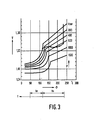
- FIG 3 shows the pressure curve in the interior of the tool for a specific molded part which consists of the material polypropylene.
- the pressure in the mold is suddenly increased from 1 bar to approx. 700 bar at a temperature of approx. 230 ° C.
- the pressure becomes slow reduced to 1 bar and at the same time the temperature of the molded part cooled to approx. 120 ° C.
- the molded part cools down to approx. 50 ° C, whereby the molded part shrinks.
Landscapes
- Engineering & Computer Science (AREA)
- Manufacturing & Machinery (AREA)
- Mechanical Engineering (AREA)
- Injection Moulding Of Plastics Or The Like (AREA)
Applications Claiming Priority (2)
| Application Number | Priority Date | Filing Date | Title |
|---|---|---|---|
| DE19873737959 DE3737959A1 (de) | 1987-11-07 | 1987-11-07 | Verfahren zur steuerung des nachdruckzeitverlaufes einer spritzgiessmaschine |
| DE3737959 | 1987-11-07 |
Publications (3)
| Publication Number | Publication Date |
|---|---|
| EP0316035A2 true EP0316035A2 (fr) | 1989-05-17 |
| EP0316035A3 EP0316035A3 (en) | 1990-07-25 |
| EP0316035B1 EP0316035B1 (fr) | 1994-06-01 |
Family
ID=6340087
Family Applications (1)
| Application Number | Title | Priority Date | Filing Date |
|---|---|---|---|
| EP88202443A Expired - Lifetime EP0316035B1 (fr) | 1987-11-07 | 1988-11-02 | Procédé de commande de maintien en pression d'une presse d'injection |
Country Status (5)
| Country | Link |
|---|---|
| US (1) | US4983336A (fr) |
| EP (1) | EP0316035B1 (fr) |
| JP (1) | JPH01156032A (fr) |
| AT (1) | ATE106312T1 (fr) |
| DE (2) | DE3737959A1 (fr) |
Cited By (2)
| Publication number | Priority date | Publication date | Assignee | Title |
|---|---|---|---|---|
| EP0436732A1 (fr) * | 1989-07-27 | 1991-07-17 | Fanuc Ltd. | Regulateur de pression d'injection pour machine de moulage a injection a moteur |
| DE10239591B4 (de) * | 2001-08-29 | 2006-04-13 | Moog Inc. | Einzelmotoreinspritz- und Schraubenantriebshybridaktuator |
Families Citing this family (15)
| Publication number | Priority date | Publication date | Assignee | Title |
|---|---|---|---|---|
| US5251146A (en) * | 1988-02-05 | 1993-10-05 | Fanuc Ltd. | Injection compression molding method and an apparatus therefor |
| DE59103470D1 (de) * | 1990-06-13 | 1994-12-15 | Ciba Geigy Ag | Verfahren zum Überprüfen des Gelierprozesses nach dem Giessen eines reaktiven Harzsystems in eine Produktionsform. |
| US5296174A (en) * | 1991-03-19 | 1994-03-22 | Japan Steel Works Co., Ltd. | Method of controlling holding pressure in injection molding and apparatus therefor |
| US6192283B1 (en) | 1998-07-31 | 2001-02-20 | Siemens Energy & Automation, Inc. | Method and apparatus for adaptive control of a system or device |
| AU2002235156A1 (en) * | 2000-11-06 | 2002-05-15 | Frederick J. Buja | Method and apparatus for controlling a mold melt-flow process using temperature sensors |
| DE10112126B4 (de) * | 2001-03-14 | 2004-03-25 | Priamus System Technologies Ag | Verfahren zum automatischen Balancieren der volumetrischen Füllung von Kavitäten |
| DE10114228A1 (de) * | 2001-03-22 | 2002-10-02 | Frey Juergen | Verfahren zum Regeln der Schwindung von Spritzteilen |
| US20030127762A1 (en) * | 2002-01-04 | 2003-07-10 | Huang Chih Chen | Precise mold controlling method for injection molding of plastic |
| US7585166B2 (en) * | 2005-05-02 | 2009-09-08 | Buja Frederick J | System for monitoring temperature and pressure during a molding process |
| WO2007016799A1 (fr) * | 2005-08-10 | 2007-02-15 | Kistler Holding Ag | Systeme de mesure |
| US8790256B2 (en) * | 2006-08-14 | 2014-07-29 | Frederick J. Buja | System and method employing a thermocouple junction for monitoring of physiological parameters |
| US8986205B2 (en) | 2010-05-14 | 2015-03-24 | Frederick J. Buja | Sensor for measurement of temperature and pressure for a cyclic process |
| AT511391B1 (de) * | 2011-10-18 | 2013-02-15 | Engel Austria Gmbh | Verfahren zur quantifizierung von prozessschwankungen bei einem einspritzvorgang einer spritzgiessmaschine |
| TWI725300B (zh) * | 2018-04-10 | 2021-04-21 | 中原大學 | 射出成型設備及射出成型方法 |
| DE102021117769A1 (de) | 2021-07-09 | 2023-01-12 | Dr. Ing. H.C. F. Porsche Aktiengesellschaft | Verfahren zum Herstellen eines Stators oder Rotors und eine elektrische Maschine |
Family Cites Families (1)
| Publication number | Priority date | Publication date | Assignee | Title |
|---|---|---|---|---|
| JPS60139422A (ja) * | 1983-12-28 | 1985-07-24 | Fanuc Ltd | 射出成形機 |
-
1987
- 1987-11-07 DE DE19873737959 patent/DE3737959A1/de not_active Withdrawn
-
1988
- 1988-11-02 EP EP88202443A patent/EP0316035B1/fr not_active Expired - Lifetime
- 1988-11-02 AT AT88202443T patent/ATE106312T1/de not_active IP Right Cessation
- 1988-11-02 DE DE3889857T patent/DE3889857D1/de not_active Expired - Fee Related
- 1988-11-07 JP JP63279528A patent/JPH01156032A/ja active Pending
-
1990
- 1990-01-05 US US07/462,992 patent/US4983336A/en not_active Expired - Fee Related
Non-Patent Citations (3)
| Title |
|---|
| KUNSTSTOFFBERATER, Band 25, Januar/Februar 1980, Seiten 31-33; W. BONGARDT et al.: "Selbsteinstellende mikrorechnergef}hrte Spritzgiessmaschine" * |
| KUNSTSTOFFE, Band 73, Nr. 5, Mai 1983, Seiten 241-245, M}nchen, DE; K. GISSING et al.: "Zum optimalen Nachdruckverlauf beim Spritzgiessen thermoplastischer Kunststoffe" * |
| PLASTVERARBEITER, Band 35, Nr. 5, Mai 1984, Seiten 74-81, Speyer, DE; W. KOTZAB: "Exakte Temperierung bei geringem Kostenaufwand" * |
Cited By (3)
| Publication number | Priority date | Publication date | Assignee | Title |
|---|---|---|---|---|
| EP0436732A1 (fr) * | 1989-07-27 | 1991-07-17 | Fanuc Ltd. | Regulateur de pression d'injection pour machine de moulage a injection a moteur |
| EP0436732A4 (en) * | 1989-07-27 | 1991-12-11 | Fanuc Ltd. | Injection pressure controller of motor-operated injection molding machine |
| DE10239591B4 (de) * | 2001-08-29 | 2006-04-13 | Moog Inc. | Einzelmotoreinspritz- und Schraubenantriebshybridaktuator |
Also Published As
| Publication number | Publication date |
|---|---|
| EP0316035B1 (fr) | 1994-06-01 |
| DE3737959A1 (de) | 1989-05-18 |
| EP0316035A3 (en) | 1990-07-25 |
| US4983336A (en) | 1991-01-08 |
| DE3889857D1 (de) | 1994-07-07 |
| JPH01156032A (ja) | 1989-06-19 |
| ATE106312T1 (de) | 1994-06-15 |
Similar Documents
| Publication | Publication Date | Title |
|---|---|---|
| EP0316035B1 (fr) | Procédé de commande de maintien en pression d'une presse d'injection | |
| DE2253506C3 (de) | Regeleinrichtung für die Einspritzeinheit einer Schnecken-Spritzgießmaschine | |
| DE3725167C2 (de) | Verfahren zur Steuerung der Formzuhaltung sowie Kompression eines in einem Formraum einer Spritzgießform eingespritzen Kunststoffes einer Spritzgießmaschine sowie Spritzgießmaschine | |
| DE2148917C3 (de) | Vorrichtung zur optimierenden Einstellung der Drehzahl einer drehbaren und axial verschiebbaren PIastifizierschnecke einer Kunststotfspritzgießmaschine | |
| EP2583811B2 (fr) | Procédé de quantification de basculements de procédés dans le cadre d'un processus d'injection d'une machine de moulage par injection | |
| DE2743845A1 (de) | System zur automatischen ueberwachung der werkzeuglebensdauer | |
| DE102016002521B4 (de) | Druckregelvorrichtung für eine Spritzgießmaschine | |
| EP3291958A1 (fr) | Détermination de valeurs de paramètre de processus dans un processus de moulage par injection | |
| DE3830571A1 (de) | Berechnungsverfahren fuer die stroemungsanalyse beim spritzgiessen | |
| DE102011102313A1 (de) | Steuerung für eine Spritzgießmaschine mit einem Plastifizierungszustand-Überwachungsmittel | |
| DE102013003725A1 (de) | Steuervorrichtung für die andrückkraft einer spritzdüse für eine spritzgiessmaschine | |
| DE4002398C2 (de) | Vorrichtung zum Steuern der Einregelung der Gießbedingungen einer Spritzgießmaschine | |
| DE60104348T2 (de) | Verfahren und Vorrichtung zum Steuern einer Spritzgiessmaschine geeignet zum Reduzieren der Gewichtsänderungen von Formkörpern | |
| DE102013012067A1 (de) | Spritzgussmaschine mit Gießharzzuführmengenregulierer | |
| EP0461143B1 (fr) | Procede pour reguler la phase de maintien en pression lors de l'injection de thermoplastiques | |
| DE2605037A1 (de) | Verfahren und vorrichtung zum zyklischen spritzgiessen von kunststoff- formteilen | |
| DE102013005078B4 (de) | Regelvorrichtung für eine Spritzgießmaschine mit einer Funktion zur Einstellung von Parametern für die Druckregelung | |
| DE2940152A1 (de) | Verfahren und vorrichtung zum regeln des plastifizierens eines harzes in einer reihenschnecken-spritzgussmaschine | |
| DE3801216A1 (de) | Verfahren und vorrichtung zum steuern von spritzgiessmaschinen | |
| DE3229810A1 (de) | Vorrichtung zum plastifizieren von kunststoffen | |
| EP0077847A1 (fr) | Dispositif à mouler par injection pour machines à mouler par injection et/ou outils à mouler par injection | |
| DE2523303A1 (de) | Vorrichtung zur hydraulischen steuerung des spritzdrucks, nachdrucks und staudrucks von spritzgiessmaschinen | |
| EP3892440A1 (fr) | Procédé de réglage d'une machine de moulage par injection | |
| EP0421134B1 (fr) | Procédé pour la fabrication par injection de pièces moulées à partir de masses de matière plastique | |
| DE3138432A1 (de) | Verfahren und anordnung zur optimierung eines spritzgiessprozesses |
Legal Events
| Date | Code | Title | Description |
|---|---|---|---|
| PUAI | Public reference made under article 153(3) epc to a published international application that has entered the european phase |
Free format text: ORIGINAL CODE: 0009012 |
|
| AK | Designated contracting states |
Kind code of ref document: A2 Designated state(s): AT CH DE FR GB IT LI NL |
|
| PUAL | Search report despatched |
Free format text: ORIGINAL CODE: 0009013 |
|
| AK | Designated contracting states |
Kind code of ref document: A3 Designated state(s): AT CH DE FR GB IT LI NL |
|
| 17P | Request for examination filed |
Effective date: 19901219 |
|
| 17Q | First examination report despatched |
Effective date: 19920304 |
|
| GRAA | (expected) grant |
Free format text: ORIGINAL CODE: 0009210 |
|
| AK | Designated contracting states |
Kind code of ref document: B1 Designated state(s): AT CH DE FR GB IT LI NL |
|
| PG25 | Lapsed in a contracting state [announced via postgrant information from national office to epo] |
Ref country code: NL Effective date: 19940601 |
|
| REF | Corresponds to: |
Ref document number: 106312 Country of ref document: AT Date of ref document: 19940615 Kind code of ref document: T |
|
| REF | Corresponds to: |
Ref document number: 3889857 Country of ref document: DE Date of ref document: 19940707 |
|
| ITF | It: translation for a ep patent filed |
Owner name: ING. C. GREGORJ S.P.A. |
|
| GBT | Gb: translation of ep patent filed (gb section 77(6)(a)/1977) |
Effective date: 19940905 |
|
| ET | Fr: translation filed | ||
| NLV1 | Nl: lapsed or annulled due to failure to fulfill the requirements of art. 29p and 29m of the patents act | ||
| PLBE | No opposition filed within time limit |
Free format text: ORIGINAL CODE: 0009261 |
|
| STAA | Information on the status of an ep patent application or granted ep patent |
Free format text: STATUS: NO OPPOSITION FILED WITHIN TIME LIMIT |
|
| ITPR | It: changes in ownership of a european patent |
Owner name: CAMBIO RAGIONE SOCIALE;PHILIPS ELECTRONICS N.V. |
|
| REG | Reference to a national code |
Ref country code: CH Ref legal event code: PFA Free format text: PHILIPS ELECTRONICS N.V. |
|
| 26N | No opposition filed | ||
| REG | Reference to a national code |
Ref country code: FR Ref legal event code: CD |
|
| PGFP | Annual fee paid to national office [announced via postgrant information from national office to epo] |
Ref country code: DE Payment date: 19960125 Year of fee payment: 8 |
|
| PGFP | Annual fee paid to national office [announced via postgrant information from national office to epo] |
Ref country code: GB Payment date: 19961101 Year of fee payment: 9 |
|
| PGFP | Annual fee paid to national office [announced via postgrant information from national office to epo] |
Ref country code: FR Payment date: 19961119 Year of fee payment: 9 |
|
| PGFP | Annual fee paid to national office [announced via postgrant information from national office to epo] |
Ref country code: AT Payment date: 19961125 Year of fee payment: 9 |
|
| PGFP | Annual fee paid to national office [announced via postgrant information from national office to epo] |
Ref country code: CH Payment date: 19970217 Year of fee payment: 9 |
|
| PG25 | Lapsed in a contracting state [announced via postgrant information from national office to epo] |
Ref country code: DE Effective date: 19970801 |
|
| PG25 | Lapsed in a contracting state [announced via postgrant information from national office to epo] |
Ref country code: GB Free format text: LAPSE BECAUSE OF NON-PAYMENT OF DUE FEES Effective date: 19971102 Ref country code: AT Free format text: LAPSE BECAUSE OF NON-PAYMENT OF DUE FEES Effective date: 19971102 |
|
| PG25 | Lapsed in a contracting state [announced via postgrant information from national office to epo] |
Ref country code: LI Free format text: LAPSE BECAUSE OF THE APPLICANT RENOUNCES Effective date: 19971130 Ref country code: FR Free format text: THE PATENT HAS BEEN ANNULLED BY A DECISION OF A NATIONAL AUTHORITY Effective date: 19971130 Ref country code: CH Free format text: LAPSE BECAUSE OF THE APPLICANT RENOUNCES Effective date: 19971130 |
|
| REG | Reference to a national code |
Ref country code: CH Ref legal event code: PL |
|
| GBPC | Gb: european patent ceased through non-payment of renewal fee |
Effective date: 19971102 |
|
| REG | Reference to a national code |
Ref country code: FR Ref legal event code: ST |
|
| PG25 | Lapsed in a contracting state [announced via postgrant information from national office to epo] |
Ref country code: IT Free format text: LAPSE BECAUSE OF NON-PAYMENT OF DUE FEES;WARNING: LAPSES OF ITALIAN PATENTS WITH EFFECTIVE DATE BEFORE 2007 MAY HAVE OCCURRED AT ANY TIME BEFORE 2007. THE CORRECT EFFECTIVE DATE MAY BE DIFFERENT FROM THE ONE RECORDED. Effective date: 20051102 |