EP0315323B1 - Shuttering - Google Patents
Shuttering Download PDFInfo
- Publication number
- EP0315323B1 EP0315323B1 EP88309221A EP88309221A EP0315323B1 EP 0315323 B1 EP0315323 B1 EP 0315323B1 EP 88309221 A EP88309221 A EP 88309221A EP 88309221 A EP88309221 A EP 88309221A EP 0315323 B1 EP0315323 B1 EP 0315323B1
- Authority
- EP
- European Patent Office
- Prior art keywords
- fabric
- plate
- shuttering
- face
- tissue
- Prior art date
- Legal status (The legal status is an assumption and is not a legal conclusion. Google has not performed a legal analysis and makes no representation as to the accuracy of the status listed.)
- Expired - Lifetime
Links
Images


Classifications
-
- B—PERFORMING OPERATIONS; TRANSPORTING
- B28—WORKING CEMENT, CLAY, OR STONE
- B28B—SHAPING CLAY OR OTHER CERAMIC COMPOSITIONS; SHAPING SLAG; SHAPING MIXTURES CONTAINING CEMENTITIOUS MATERIAL, e.g. PLASTER
- B28B7/00—Moulds; Cores; Mandrels
- B28B7/36—Linings or coatings, e.g. removable, absorbent linings, permanent anti-stick coatings; Linings becoming a non-permanent layer of the moulded article
- B28B7/368—Absorbent linings
-
- E—FIXED CONSTRUCTIONS
- E04—BUILDING
- E04G—SCAFFOLDING; FORMS; SHUTTERING; BUILDING IMPLEMENTS OR AIDS, OR THEIR USE; HANDLING BUILDING MATERIALS ON THE SITE; REPAIRING, BREAKING-UP OR OTHER WORK ON EXISTING BUILDINGS
- E04G9/00—Forming or shuttering elements for general use
- E04G9/10—Forming or shuttering elements for general use with additional peculiarities such as surface shaping, insulating or heating, permeability to water or air
Definitions
- This invention relates to a shuttering used for forming concrete.
- a shuttering comprising a plate and two fabrics sewed to each other and covering the surface of the plate.
- the two fabrics consist of an inner fabric adhered to the surface of said plate and an outer fabric which permits passage of water but prevents concrete from passing (See U.S. Patent No. 4730805).
- surplus water which has passed through the outer fabric contacting concrete is discharged in large quantities through the gap between the inner and the outer fabrics, so that the ratio of water to cement of the surface layer of formed concrete can be reduced and early removal of the form from concrete can be promoted.
- the outer fabric prevents passing of part of numerous particulate substances consisting of cement particles, aggregate particles, etc. contained in said surplus water to act as a filter which leaves these between the outer fabric and the formed concrete. The residual particles later form a surface layer of high hardness.
- the shuttering is cleaned to remove particulate substances adhered to both the fabrics for reuse after removing the form.
- the suttering can be cleaned by jetting water toward the outer fabric, but cleaning away said particulate substances from said inner fabric was too difficult to have a sufficient cleaning effect. Thus, it was unavoidable to reuse a shuttering with said particulate substances not sufficiently removed.
- the remaining particulate substances in the inner fabric combine with particulate substances in the surplus water flowing between the inner and the outer fabrics to narrow the gap between both the fabrics, preventing the surplus water form flowing, which reduces the discharge thereof.
- the particulate substances remaining the inner fabric accumulate each time the shuttering is reused, which reduces the number of reuses thereof.
- An object of this invention is to provide a shuttering consisting of a combination of a plate and a fabric with good discharging and filtering performances of surplus water, capable of more effective cleaning for reuse, and removable by less force.
- shuttering for forming concrete comprising a plate with a plurality of through holes opening on both its face and reverse, a double woven fabric attached to the plate to cover its face, consisting of a face tissue which permits passage of water but prevents concrete from passing and a reverse tissue opposed to the face of said plate, the reverse tissue defining a plurality of gaps between the plate and the fabric and being relatively displaceable with respect to said face of the plate, characterised in that wefts and warps of said face tissue have on one plane flat portions respectively which appear on the face of the fabric.
- the gaps between the plate and the face tissue of the fabric can receive in large quantities the surplus water which has passed through the face tissue of the fabric contacting concrete, and the surplus water received in said gaps is discharged through the through holes.
- Said face tissue of the fabric permits passage of part of numerous particulate substances consisting of cement particles and fine particles of aggregates but prevents most of them from passing through, leaving them behind in a state of layer between the face tissue and the concrete. These particulate substances later harden to form a fine surface layer of high hardness of the formed concrete.
- the reverse tissue opposed to said plate is relatively displaceable with respect to said plate, when water is jetted toward said fabric for cleaning the shuttering after removal of the form the wash water reaching said plate through said face and reverse tissues relatively displaces said reverse tissue with respect to said plate. Said particulate substances adhered to said reverse tissue are shaken off due to the relative displacement of said reverse tissue. Thus, it is possible to reuse the shuttering after sufficiently removing particulate substances adhered to the reverse tissue where cleaning effect hardly reaches.
- said fabric is also relatively displaceable on the whole with respect to the face of said plate, said fabric contacting the concrete can elongate following the settling of the concrete during cure of the concrete. Because of this, the relative displacement caused between the surface layer of the concrete contacting said fabric and the deep inner portion of the concrete can be remarkably reduced, thereby preventing separation of the surface layer when the form is removed.
- this invention is featured by the fact that the wefts and warps of the face tissue of the fabric have on one plane flat portions respectively which appear on the face of the fabric. Since the surface area of said fabric is smaller than that of the conventional fabric, the area to which concrete adheres is small. Due to this, the shuttering can be removed by a smaller force, thereby preventing separation of the surface layer of the formed concrete in removing the form. Further, since the tensile force exerted on constituting yarn of said fabric is also small, less damage is done to the constituting yarn. Accordingly, the shuttering can be more durable and reused more often. Further, it makes possible to produce a shuttering of a larger size, i.e., a large area and removable with a relatively small removing force. Using larger shutterings saves time and labor in assembling the shutterings and removing the form. Further, since less concrete adheres to the surface of a shuttering, removing the concrete for reuse of the shuttering can be easily done in a short period of time.
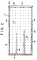
- Figs. 1 and 2 are front and rear elevations showing a shuttering relative to this invention with part thereof cut out, respectively;
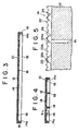
- Figs. 3 and 4 are transverse and vertical sectional views taken along the lines 3-3 and 4-4 of Fig. 1, respectively;
- Fig. 5 is a fragmentary sectional view taken along the line 5-5 of Fig. 4 and conceptionally shows the tissue of a fabric;
- Fig. 6 is a partially enlarged perspective view of the fabric;
- Fig. 7 is a partially enlarged perspective view of another fabric shown similarly to Fig. 6; and
- Fig. 8 is a partially enlarged view of another fabric viewed in the direction of the arrow A shown in fig. 7.
- the plate 12 has a plurality of through holes opening on its face 12a and its reverse 12b.
- the face 12a is preferably smooth.
- the plate 12 shown is composed of a plywood and an acrylate resin layer coated on one face thereof, the acrylate resin layer giving smoothness to the plate 12.
- the plate 12 can be composed of metal, plastic plates, etc., besides the one in the embodiment shown.
- the plate 12 is also reinforced by a plurality of bars 18 respectively extended longitudinally and vertically. Each bar 18 is fixed to the plate 12 by a plurality of driven nails 20 which extend through the fabric 14 and the plate 12 into the bar 18.
- the double woven fabric 14 consists of a face tissue 22 which permits passage of water but prevents concrete from passing and reverse tissue 24 which is integral with the face tissue 22.
- the reverse tissue 24 defines, as shown in Fig. 5, a plurality of gaps between the face tissue 22 and the plate 12.
- Four flap-like edge portions 14a communicated to the rectangular portion facing the plate surface 12a of the plate of the fabric 14 is folded back toward the reverse 12b of the plate and fixed to the reverse 12b of the plate in the neighborhood of the edge portions of the plate 12.
- the face tissue 22 of the fabric 14 defines the surface of the shuttering 10, i.e., the face abutting against concrete, while the reverse tissue 24 is relatively displaceable with respect to the face 12a.
- the edge portions 14a of the fabric can be fixed to the plate 12 by means of staples, tackers 28, etc. or an adhesive (not shown). Also, the operation to attach the fabric 14 to the plate 12 can be done at a construction site where the shuttering is used.
- the fabric 14 shown is a weft backed woven fabric composed of a face tissue 22 obtained by interlacing a plurality of wefts 22a with a plurality of warps 22b and the reverse tissue 24 obtained by interlacing the warps 22b of the face tissue with other plurality of wefts 24a.
- the face tissue 22 shown is of plain weave, and each weft 24a of the reverse tissue intersects every eighth warp 22b of the face tissue 22, constituting a tissue point together with a warp 22b.
- wefts 22a and warps 22b of the face tissue as well as wefts 24a of the reverse tissue are used, for example, twisted polypropyrene yarn (1000 deniers), twisted polyester yarn (1000 deniers) and untwisted polyester yarn (960 deniers), respectively.
- untwisted polyester yarn (1000 deniers), twisted polyester yarn (1000 deniers) and twisted polypropyrene yarn (960 deniers) can be used respectively.
- the face tissue 22 can be made to have the density of 30 pieces of 1000-denier wefts 22a and 36 pieces of 1000-denier warps 22b in a 6,25 cm2 (one-inch square) area.
- warp backed woven or warp and weft backed woven can be chosen, according to the need, and for the face tissue satin weave or twill weave can be chosen instead of plain weave shown.
- warps of the face tissue to co-operate with wefts 24a of the reverse tissue to form said tissue points can be chosen at will from among many. Further, it does not matter whether each of wefts 22a, 24a is twisted or untwisted.
- the shuttering 10, when used, is so arranged that the fabric 14 may define a contacting surface with placed concrete.
- the surplus water which oozes from said concrete gradually flows out through the face tissue 22 of the fabric 14, gaps 26 and then the through holes 16 of the plate 12.
- the reverse tissue 24 not only functions as a spacer to define the gaps 26, but also acts to lead part of said surplus water from the face tissue 22 to the holes 16 of the plate 12.
- Each gap 26 defines a passage for the surplus water which has passed through the face tissue 22.
- the face tissue 22 which prevents concrete, i.e., a mixture of cement particles, aggregates and water from passing acts as a filter to prevent passages of particulate substances consisting of cement particles, fine grain particles, etc.
- the fabric 14 Since the fabric 14 is relatively displaceable with respect to the surface of the plate 12, the fabric 14 contacting concrete is pulled by the concrete and elongated as the placed concrete settles. As a result, there does not occur such a relative displacement between the surface layer and the deep inner portion of the formed concrete as to separate said surface layer when the form is removed.
- the shuttering 10 used for forming concrete can be reused by cleaning after removal of the form.
- the shuttering 10 can be cleaned by jetting water toward the fabric 14.
- jetted water washes away said particulate substances adhered to the face tissue.
- said particulate substances adhered to the reverse tissue 24 are washed away by the pressure of said jetted water which has passed the face tissue 22.
- the reverse tissue 24 also relatively displaces with respect to the plate 12. This displacement causes particulate substances adhered to the wefts 24a of the reverse tissue 24 to be shaken off.
- the smoother the surface 12a of the plate 12 is, the more effective this shaking off is.
- most of said particulate substances are removed from the reverse tissue 24 where cleaning effect can hardly reach. Thereby the amount of said particulate substances accumulating at each use of the shuttering 10 is remarkably reduced, which makes multiple uses of the shuttering possible.
- a double woven fabric 32 having a face tissue 34 can be used.
- the wefts 34a and warps 34b appearing on the face of the fabric 32 respectively have flat portions 31 and 33 in one plane 30 (Fig. 8).
- the face tissue 34 is of plain weave, each weft 36a of the reverse tissue 36 constituting a weave point with every eight warp 34b of the face tissue while having one-to-one correspondence to a weft 34a of the face tissue and being located beneath a weft 34a of the face tissue.
- the flat portions 31 and 33 can be formed, for example, by calendering to pass fabric between a heated and an unheated rollers pressed against each other so that the face and reverse tissues abut against said heated and unheated rollers respectively.
- calendering curved convex portions of wefts and warps defining the surface of said fabric are plastically deformed, and the plastically deformed faces render flat portions 31 and 33.
- the wefts 34a and the warps 34b of the face tissue contacting said heated roller are plastically deformed to have a nearly circular to semicircular cross-sectional configuration.
- wefts 36a of the reverse tissue contacting said unheated roller and the warps 34a of the face tissue as well as the wefts 34b of the face tissue not contacting the unheated roller are plastically deformed to have a nearly circular to oval cross-sectional configuration.
- the surface of the shuttering 10, i.e., the surface of the fabric 32 has a smaller surface area, i.e., the area abutting against concrete, in comparison with the surface before calendering of the fabric, so that the removing force to be applied to the shuttering 10 in removing the form can be reduced.
- said removing force can be made smaller than when constituting same with multifilament yarn. This is because no such fluffing occurs to monofilament yarn when a portion of filament yarn is cut as is seen in multifilament yarn so that there is no adhesion between said fluff and concrete, and it is not necessary to apply to the shuttering a force to cut off the adhesion between said fluff and concrete.
- the fabric 32 is a double woven fabric with twisted polypropylene yarn (multifilament yarn of 1000 deniers), twisted polyester yarn (multifilament yarn of 1000 deniers) and untwisted polyester yarn (multifilament yarn of 960 deniers) respectively as the wefts 34a for the face tissue, the warps 34b for the face tissue and the wefts 36a for the reverse tissue. It can be obtained by calendering a fabric (fabric A) having a face tissue of satin with the texture density of 30 wefts and 36 warps in a one-inch square area under the condition that the surface temperature of the 2.2 m long heated roller is 100°C and that the pressure load against said fabric is 20 t (20,000 Kg).
- Each shuttering used in the experiment is 1 meter in both width and length.
- Said experimental values are the strengths to remove from the concrete placed in a space defined by one shuttering and three plates disposed and assembled perpendicularly to form a rectangle when on a plane and cured for 48 hours, the area of said shuttering abutting against said concrete being 0.81m2 (0.9m ⁇ 0.9m).
- Said strengths of removing forces shown in the table are the maximum values recorded by a pen recorder of the forces received by one horizontal bar when a pantograph jack and an earth pressure cell are disposed between the horizontal bar fixed to the upper end of the shuttering and another horizontal bar fixed to said two plates adjacent to the shuttering.
- the numerical values in the 1st, 2nd and 3rd experiments of the above table are values obtained respectively in case of a nonused shuttering, in case of reusing said shuttering after the first use and cleaning to wash away cement particles, powdery aggregates, etc. adhered to its surface, and in case of reusing said shuttering after the second use and cleaning.
- a face tissue composed of only monofilament yarn before said calendering has coarser meshes than one composed of multifilament yarn, and it is difficult to make them fine, while said calendering can make the meshes extremely fine.
- ultra-high-molecular-weight polyethyrene fiber (the goods name: Dyneema SK60) can be used as yarn composing a face tissue of said double woven fabric. This fiber is excellent in wear-resistance and weather-resistance.
Landscapes
- Engineering & Computer Science (AREA)
- Architecture (AREA)
- Mechanical Engineering (AREA)
- Structural Engineering (AREA)
- Civil Engineering (AREA)
- Ceramic Engineering (AREA)
- Chemical & Material Sciences (AREA)
- Manufacturing & Machinery (AREA)
- Forms Removed On Construction Sites Or Auxiliary Members Thereof (AREA)
- Moulds, Cores, Or Mandrels (AREA)
- Compositions Of Oxide Ceramics (AREA)
- Transition And Organic Metals Composition Catalysts For Addition Polymerization (AREA)
- Inorganic Insulating Materials (AREA)
Priority Applications (1)
| Application Number | Priority Date | Filing Date | Title |
|---|---|---|---|
| AT88309221T ATE67267T1 (de) | 1987-11-06 | 1988-10-04 | Schalung. |
Applications Claiming Priority (4)
| Application Number | Priority Date | Filing Date | Title |
|---|---|---|---|
| JP280393/87 | 1987-11-06 | ||
| JP62280393A JPH063069B2 (ja) | 1987-11-06 | 1987-11-06 | コンクリート成形用堰板 |
| JP305749/87 | 1987-12-04 | ||
| JP62305749A JPH0647874B2 (ja) | 1987-12-04 | 1987-12-04 | 堰板の表面形成用織物 |
Publications (2)
| Publication Number | Publication Date |
|---|---|
| EP0315323A1 EP0315323A1 (en) | 1989-05-10 |
| EP0315323B1 true EP0315323B1 (en) | 1991-09-11 |
Family
ID=26553756
Family Applications (1)
| Application Number | Title | Priority Date | Filing Date |
|---|---|---|---|
| EP88309221A Expired - Lifetime EP0315323B1 (en) | 1987-11-06 | 1988-10-04 | Shuttering |
Country Status (9)
| Country | Link |
|---|---|
| US (1) | US4856754A (no) |
| EP (1) | EP0315323B1 (no) |
| KR (1) | KR890008415A (no) |
| AU (1) | AU593446B2 (no) |
| DE (1) | DE3864797D1 (no) |
| ES (1) | ES2025292B3 (no) |
| HK (1) | HK54592A (no) |
| NO (1) | NO170773C (no) |
| SE (1) | SE466095B (no) |
Families Citing this family (47)
| Publication number | Priority date | Publication date | Assignee | Title |
|---|---|---|---|---|
| FR2641588B1 (fr) * | 1989-01-09 | 1991-03-22 | Degremont | Dispositif pour la mise en place et la fixation, sur le plancher d'un filtre, d'organes assurant le transit de fluides a travers le plancher |
| ATE88944T1 (de) * | 1989-11-20 | 1993-05-15 | Du Pont | Schaltung fuer gemusterten beton. |
| DE68905481T2 (de) * | 1989-12-01 | 1993-06-24 | Central Eng Co Ltd | Zusammengesetztes material zum anbringen an schalungspaneelen. |
| US5124102A (en) * | 1990-12-11 | 1992-06-23 | E. I. Du Pont De Nemours And Company | Fabric useful as a concrete form liner |
| US5125813A (en) * | 1991-07-12 | 1992-06-30 | Roestenberg Jerome R | Molding plate |
| US5206981A (en) * | 1991-10-25 | 1993-05-04 | E. I. Du Pont De Nemours And Company | Fabric tensioning frame |
| US5247730A (en) * | 1991-10-25 | 1993-09-28 | E. I. Du Pont De Nemours And Company | Method for attaching and bidirectionally tensioning a porous fabric over a form support |
| US5302099A (en) * | 1992-09-28 | 1994-04-12 | E. I. Du Pont De Nemours And Company | Laminated fabric useful as a concrete form liner |
| GB9309066D0 (en) * | 1993-05-01 | 1993-06-16 | Green Barry E | Filter fabric |
| DE19623584B4 (de) * | 1996-06-13 | 2004-10-14 | Johns Manville International, Inc., Denver | Textiles Flächengebilde zur Verwendung als Betonformzwischenlage |
| IT1294828B1 (it) * | 1997-07-24 | 1999-04-15 | Longinotti Meccanica S R L | Apparecchiatura per produrre mattonelle sottili di impasto cementizio |
| DE19812517C2 (de) | 1998-03-21 | 2000-06-21 | Johns Manville Int Inc | Betonschalung zur Herstellung von Betonartikeln |
| DE19834983C1 (de) * | 1998-08-03 | 1999-09-16 | Fibertex As | Betonschaltung und Verfahren zur Herstellung einer Betonschalung |
| CA2302972A1 (en) * | 2000-03-29 | 2001-09-29 | Francesco Piccone | Apertured wall element |
| US6682671B1 (en) | 2000-05-18 | 2004-01-27 | The United States Of America As Represented By The Secretary Of The Army | Method of manufacturing fiber-reinforced structures incorporating recycled carpet fibers |
| KR20010044609A (ko) * | 2001-03-12 | 2001-06-05 | 한기홍 | 황토벽체 시공용 거푸집 패널 |
| DE10114161A1 (de) * | 2001-03-22 | 2002-09-26 | Thyssen Huennebeck Gmbh | Schalungselement und Verfahren zum Herstellen und Reparieren desselben |
| JP3863749B2 (ja) * | 2001-10-02 | 2006-12-27 | 日清紡績株式会社 | 経二重織デニム |
| US20040069925A1 (en) * | 2002-10-09 | 2004-04-15 | Durand Forms Incorporated | Concrete forming panel and method for making same |
| US7871055B1 (en) * | 2006-04-24 | 2011-01-18 | University Of Maine System Board Of Trustees | Lightweight composite concrete formwork panel |
| CN101680234A (zh) * | 2007-04-02 | 2010-03-24 | Cfs混凝土模板系统公司 | 在混凝土结构体上提供衬里的方法和设备 |
| CA2705026C (en) | 2007-11-09 | 2013-07-02 | Cfs Concrete Forming Systems Inc. | Pivotally activated connector components for form-work systems and methods for use of same |
| WO2009092158A1 (en) * | 2008-01-21 | 2009-07-30 | Octaform Systems Inc. | Stay-in-place form systems for windows and other building openings |
| US8943774B2 (en) | 2009-04-27 | 2015-02-03 | Cfs Concrete Forming Systems Inc. | Methods and apparatus for restoring, repairing, reinforcing and/or protecting structures using concrete |
| EP4249705A3 (en) | 2009-01-07 | 2023-12-06 | CFS Concrete Forming Systems Inc. | Method and apparatus for restoring, repairing, reinforcing and/or protecting structures using concrete |
| DE102009004573A1 (de) | 2009-01-14 | 2010-07-15 | Johns Manville Europe Gmbh | Betonschalung, Verfahren zu deren Herstellung und deren Verwendung |
| DE202009000393U1 (de) | 2009-01-14 | 2009-03-19 | Johns Manville Europe Gmbh | Betonschalung |
| WO2010094111A1 (en) | 2009-02-18 | 2010-08-26 | Cfs Concrete Forming Systems Inc. | Clip-on connection system for stay-in-place form-work |
| EP2591186B1 (en) | 2010-07-06 | 2019-05-01 | CFS Concrete Forming Systems Inc. | Push on system for repairing structures |
| CA2855742C (en) | 2011-11-24 | 2019-10-29 | Cfs Concrete Forming Systems Inc. | Stay-in place formwork with engaging and abutting connections |
| WO2013075250A1 (en) | 2011-11-24 | 2013-05-30 | Cfs Concrete Forming Systems Inc. | Stay-in-place formwork with anti-deformation panels |
| WO2013102274A1 (en) | 2012-01-05 | 2013-07-11 | Cfs Concrete Forming Systems Inc. | Panel-to-panel connections for stay-in-place liners used to repair structures |
| CA2988025C (en) | 2012-01-05 | 2018-08-14 | Cfs Concrete Forming Systems Inc. | Systems for restoring, repairing, reinforcing, protecting, insulating and/or cladding structures with locatable stand-off components |
| US10151119B2 (en) | 2012-01-05 | 2018-12-11 | Cfs Concrete Forming Systems Inc. | Tool for making panel-to-panel connections for stay-in-place liners used to repair structures and methods for using same |
| US9458637B2 (en) * | 2012-09-25 | 2016-10-04 | Romeo Ilarian Ciuperca | Composite insulated plywood, insulated plywood concrete form and method of curing concrete using same |
| US10065339B2 (en) | 2013-05-13 | 2018-09-04 | Romeo Ilarian Ciuperca | Removable composite insulated concrete form, insulated precast concrete table and method of accelerating concrete curing using same |
| CA2911409C (en) | 2013-05-13 | 2021-03-02 | Romeo Ilarian Ciuperca | Insulated concrete battery mold, insulated passive concrete curing system, accelerated concrete curing apparatus and method of using same |
| AU2014315033A1 (en) | 2013-09-09 | 2016-03-31 | Romeo Ilarian Ciuperca | Insulated concrete slip form and method of accelerating concrete curing using same |
| CA2932453C (en) | 2013-12-06 | 2022-07-12 | Cfs Concrete Forming Systems Inc. | Structure cladding trim components and methods for fabrication and use of same |
| EP3126587B1 (en) | 2014-04-04 | 2023-06-07 | CFS Concrete Forming Systems Inc. | Liquid and gas-impermeable connections for panels of stay- in-place form-work systems |
| CN105604233B (zh) * | 2015-12-23 | 2017-11-14 | 武汉纺织大学 | 一种纤维织物养护‑饰面混凝土构件及其制备方法 |
| CN108463599B (zh) | 2015-12-31 | 2020-11-03 | Cfs 混凝土模板系统公司 | 具有可调节宽度的结构衬里装置和用于该装置的工具 |
| US10280622B2 (en) | 2016-01-31 | 2019-05-07 | Romeo Ilarian Ciuperca | Self-annealing concrete forms and method of making and using same |
| CN110494615B (zh) | 2017-04-03 | 2022-08-02 | Cfs 混凝土模板系统公司 | 大跨度保持原位衬里 |
| CA3084840C (en) | 2017-12-22 | 2024-04-16 | Cfs Concrete Forming Systems Inc. | Snap-together standoffs for restoring, repairing, reinforcing, protecting, insulating and/or cladding structures |
| AU2020218008A1 (en) | 2019-02-08 | 2021-09-16 | Cfs Concrete Forming Systems Inc. | Retainers for restoring, repairing, reinforcing, protecting, insulating and/or cladding structures |
| CN111424961A (zh) * | 2020-04-03 | 2020-07-17 | 中国建筑第八工程局有限公司 | 一种便于透气的清水混凝土模板 |
Family Cites Families (3)
| Publication number | Priority date | Publication date | Assignee | Title |
|---|---|---|---|---|
| US2310391A (en) * | 1941-06-28 | 1943-02-09 | Us Rubber Co | Absorptive mold lining |
| GB2175635B (en) * | 1985-05-28 | 1988-06-08 | Kumagai Gumi Co Ltd | Formwork |
| JPS6290470A (ja) * | 1985-10-17 | 1987-04-24 | 株式会社熊谷組 | コンクリ−ト型枠装置 |
-
1988
- 1988-06-03 US US07/202,108 patent/US4856754A/en not_active Expired - Fee Related
- 1988-06-07 AU AU17443/88A patent/AU593446B2/en not_active Ceased
- 1988-06-08 SE SE8802139A patent/SE466095B/sv not_active IP Right Cessation
- 1988-06-24 KR KR1019880007671A patent/KR890008415A/ko not_active Application Discontinuation
- 1988-10-04 ES ES88309221T patent/ES2025292B3/es not_active Expired - Lifetime
- 1988-10-04 DE DE8888309221T patent/DE3864797D1/de not_active Expired - Lifetime
- 1988-10-04 EP EP88309221A patent/EP0315323B1/en not_active Expired - Lifetime
- 1988-11-04 NO NO884933A patent/NO170773C/no not_active IP Right Cessation
-
1992
- 1992-07-23 HK HK545/92A patent/HK54592A/xx not_active IP Right Cessation
Also Published As
| Publication number | Publication date |
|---|---|
| NO170773B (no) | 1992-08-24 |
| ES2025292B3 (es) | 1992-03-16 |
| US4856754A (en) | 1989-08-15 |
| EP0315323A1 (en) | 1989-05-10 |
| NO884933L (no) | 1989-05-08 |
| NO884933D0 (no) | 1988-11-04 |
| NO170773C (no) | 1992-12-02 |
| SE8802139D0 (sv) | 1988-06-08 |
| AU1744388A (en) | 1989-05-11 |
| AU593446B2 (en) | 1990-02-08 |
| DE3864797D1 (de) | 1991-10-17 |
| SE466095B (sv) | 1991-12-16 |
| HK54592A (en) | 1992-07-30 |
| KR890008415A (ko) | 1989-07-10 |
| SE8802139L (sv) | 1989-05-07 |
Similar Documents
| Publication | Publication Date | Title |
|---|---|---|
| EP0315323B1 (en) | Shuttering | |
| EP1458912B1 (de) | Gittergewebe | |
| HUE025834T2 (en) | Industrial film | |
| EP0716903A1 (de) | Schleifmittel auf Unterlage | |
| EP0664100A1 (de) | Wischbezug | |
| EP1115314B1 (de) | Bodenteppich-verlegesystem | |
| EP1240372B1 (de) | Gittergewebe | |
| JP2510868B2 (ja) | 堰板の表面形成用織物 | |
| EP0811350B1 (de) | Reinigungstuch zur Befestigung an einem Reinigungstuchhalter | |
| JPH0647874B2 (ja) | 堰板の表面形成用織物 | |
| DE2361711A1 (de) | Filz, insbesondere papiermaschinenfilz | |
| DE19609492C2 (de) | Gewebe | |
| DE102010019242B4 (de) | Textiles Trägermaterial für Schleifmittel und Schleifmittelmaterial | |
| DE3915810A1 (de) | Flexibler schleifkoerper | |
| JPH063069B2 (ja) | コンクリート成形用堰板 | |
| JP2510883B2 (ja) | コンクリ―ト成形用堰板 | |
| DE20020316U1 (de) | Schalldämmende Trägerbahn für Bodenbeläge, insbesondere Plattenbeläge | |
| WO1991016501A1 (de) | Schalungshülle | |
| EP0591963A1 (de) | Hinterfüllmatte | |
| DE102019127675B4 (de) | Fußmatte mit erhöhter Schmutzaufnahmefunktion | |
| DE1759259C3 (de) | Matte zur Befestigung von Dämmen, Deichen und Böschungen | |
| JPS607379Y2 (ja) | 土木工事用マツト | |
| WO1981000582A1 (en) | Framing for making concrete slabs | |
| EP1792698A2 (de) | Platte | |
| EP1115315B1 (de) | Bodenteppich-verlegesystem |
Legal Events
| Date | Code | Title | Description |
|---|---|---|---|
| PUAI | Public reference made under article 153(3) epc to a published international application that has entered the european phase |
Free format text: ORIGINAL CODE: 0009012 |
|
| AK | Designated contracting states |
Kind code of ref document: A1 Designated state(s): AT CH DE ES FR GB IT LI |
|
| 17P | Request for examination filed |
Effective date: 19890629 |
|
| 17Q | First examination report despatched |
Effective date: 19900629 |
|
| GRAA | (expected) grant |
Free format text: ORIGINAL CODE: 0009210 |
|
| AK | Designated contracting states |
Kind code of ref document: B1 Designated state(s): AT CH DE ES FR GB IT LI |
|
| REF | Corresponds to: |
Ref document number: 67267 Country of ref document: AT Date of ref document: 19910915 Kind code of ref document: T |
|
| ITF | It: translation for a ep patent filed |
Owner name: BARZANO' E ZANARDO ROMA S.P.A. |
|
| REF | Corresponds to: |
Ref document number: 3864797 Country of ref document: DE Date of ref document: 19911017 |
|
| ET | Fr: translation filed | ||
| REG | Reference to a national code |
Ref country code: ES Ref legal event code: FG2A Ref document number: 2025292 Country of ref document: ES Kind code of ref document: B3 |
|
| PLBE | No opposition filed within time limit |
Free format text: ORIGINAL CODE: 0009261 |
|
| STAA | Information on the status of an ep patent application or granted ep patent |
Free format text: STATUS: NO OPPOSITION FILED WITHIN TIME LIMIT |
|
| 26N | No opposition filed | ||
| PGFP | Annual fee paid to national office [announced via postgrant information from national office to epo] |
Ref country code: GB Payment date: 19960912 Year of fee payment: 9 |
|
| PGFP | Annual fee paid to national office [announced via postgrant information from national office to epo] |
Ref country code: DE Payment date: 19960923 Year of fee payment: 9 |
|
| PGFP | Annual fee paid to national office [announced via postgrant information from national office to epo] |
Ref country code: FR Payment date: 19960926 Year of fee payment: 9 |
|
| PGFP | Annual fee paid to national office [announced via postgrant information from national office to epo] |
Ref country code: CH Payment date: 19961001 Year of fee payment: 9 Ref country code: AT Payment date: 19961001 Year of fee payment: 9 |
|
| PGFP | Annual fee paid to national office [announced via postgrant information from national office to epo] |
Ref country code: ES Payment date: 19961011 Year of fee payment: 9 |
|
| PG25 | Lapsed in a contracting state [announced via postgrant information from national office to epo] |
Ref country code: GB Free format text: LAPSE BECAUSE OF NON-PAYMENT OF DUE FEES Effective date: 19971004 Ref country code: AT Free format text: LAPSE BECAUSE OF NON-PAYMENT OF DUE FEES Effective date: 19971004 |
|
| PG25 | Lapsed in a contracting state [announced via postgrant information from national office to epo] |
Ref country code: ES Free format text: LAPSE BECAUSE OF THE APPLICANT RENOUNCES Effective date: 19971006 |
|
| PG25 | Lapsed in a contracting state [announced via postgrant information from national office to epo] |
Ref country code: LI Free format text: LAPSE BECAUSE OF NON-PAYMENT OF DUE FEES Effective date: 19971031 Ref country code: FR Free format text: THE PATENT HAS BEEN ANNULLED BY A DECISION OF A NATIONAL AUTHORITY Effective date: 19971031 Ref country code: CH Free format text: LAPSE BECAUSE OF NON-PAYMENT OF DUE FEES Effective date: 19971031 |
|
| GBPC | Gb: european patent ceased through non-payment of renewal fee |
Effective date: 19971004 |
|
| REG | Reference to a national code |
Ref country code: CH Ref legal event code: PL |
|
| PG25 | Lapsed in a contracting state [announced via postgrant information from national office to epo] |
Ref country code: DE Free format text: LAPSE BECAUSE OF NON-PAYMENT OF DUE FEES Effective date: 19980701 |
|
| REG | Reference to a national code |
Ref country code: FR Ref legal event code: ST |
|
| REG | Reference to a national code |
Ref country code: ES Ref legal event code: FD2A Effective date: 20001102 |
|
| PG25 | Lapsed in a contracting state [announced via postgrant information from national office to epo] |
Ref country code: IT Free format text: LAPSE BECAUSE OF NON-PAYMENT OF DUE FEES;WARNING: LAPSES OF ITALIAN PATENTS WITH EFFECTIVE DATE BEFORE 2007 MAY HAVE OCCURRED AT ANY TIME BEFORE 2007. THE CORRECT EFFECTIVE DATE MAY BE DIFFERENT FROM THE ONE RECORDED. Effective date: 20051004 |