EP0315065A1 - Vorrichtung zum Aufrichten eines Trägers - Google Patents
Vorrichtung zum Aufrichten eines Trägers Download PDFInfo
- Publication number
- EP0315065A1 EP0315065A1 EP88117975A EP88117975A EP0315065A1 EP 0315065 A1 EP0315065 A1 EP 0315065A1 EP 88117975 A EP88117975 A EP 88117975A EP 88117975 A EP88117975 A EP 88117975A EP 0315065 A1 EP0315065 A1 EP 0315065A1
- Authority
- EP
- European Patent Office
- Prior art keywords
- objects
- carrier
- holes
- transport
- devices
- Prior art date
- Legal status (The legal status is an assumption and is not a legal conclusion. Google has not performed a legal analysis and makes no representation as to the accuracy of the status listed.)
- Granted
Links
Images


Classifications
-
- B—PERFORMING OPERATIONS; TRANSPORTING
- B65—CONVEYING; PACKING; STORING; HANDLING THIN OR FILAMENTARY MATERIAL
- B65B—MACHINES, APPARATUS OR DEVICES FOR, OR METHODS OF, PACKAGING ARTICLES OR MATERIALS; UNPACKING
- B65B11/00—Wrapping, e.g. partially or wholly enclosing, articles or quantities of material, in strips, sheets or blanks, of flexible material
- B65B11/06—Wrapping articles, or quantities of material, by conveying wrapper and contents in common defined paths
- B65B11/08—Wrapping articles, or quantities of material, by conveying wrapper and contents in common defined paths in a single straight path
- B65B11/10—Wrapping articles, or quantities of material, by conveying wrapper and contents in common defined paths in a single straight path to fold the wrappers in tubular form about contents
- B65B11/105—Wrapping articles, or quantities of material, by conveying wrapper and contents in common defined paths in a single straight path to fold the wrappers in tubular form about contents the axis of the tube being parallel to the conveying direction
Definitions
- the invention relates to a device for erecting a carrier from a flat blank of cardboard or the like.
- a device for erecting a carrier from a flat blank of cardboard or the like For cup-shaped or can-shaped objects which are inserted in holes in a carrier plate of the carrier, on which upwardly projecting tabs which are in contact with the outside of the objects are formed are.
- the invention has for its object to provide a device with which such a carrier can be erected in a simple and rational manner and equipped with objects.
- This object is achieved in that a substantially horizontally extending transport device for the cardboard blank is provided, to which another transport device runs at an acute angle, which carries upward tappets, which into the holes of the support plate of the carrier blank are able to intervene.
- the blank is prepared for inserting the objects in a simple manner.
- a feed device for the cup-shaped or can-shaped objects is provided above the two transport devices, with the aid of which the objects can be placed on the plungers inserted from below through the holes in the support plate, wherein the plungers have at least approximately the same cross-sectional shape as the bottoms of the objects and if, furthermore, in the further course of the transport and feed devices, these run in such a way that the plungers are moved out of the holes and at the same time the objects are moved into the holes.
- Another very advantageous embodiment of the invention is that following the converging transport and supply devices, guide devices are provided which fold the bottom flaps of the carrier projecting downward against one another. This means that the erection of the girder also runs fully automatically on the same device.
- a glue nozzle is provided at the beginning of the guide devices, which glue injects an adhesive onto the inside of the one bottom flap, which is on the outside when folded.
- a pressing device is provided on the underside of the devices, which presses the two bottom flaps folded over one another.
- a further advantageous embodiment according to the invention is that a folding device is provided, by means of which a sleeve-shaped outer packaging can be wrapped around the carrier equipped with the objects.
- FIG. 1 in FIG. 1 denotes a cardboard blank which has a support plate 2 in which holes 3 are provided for receiving cup-shaped objects 4. Tabs 5 protrude into the holes 3 and are hinged to the support plate 2 via a fold line 6. Also on the support plate 2, two side walls 7 and 8 are articulated via fold lines 9 and 10. Tabs 11 are formed on these side walls 7 and 8 and extend beyond the two fold lines 9 and 10, respectively protrude into holes 3. The two other edges of the support plate 2 are connected to further side walls 14 and 15 via fold lines 12, 13 and these in turn are connected to bottom flaps 18, 19 via fold lines 16, 17.
- a carrier 20 is shown, which is fully erected, closed at the bottom and equipped with cup-shaped objects 4.
- the flaps 5 and the flaps 11 formed on the side walls 7 and 8 are bent upwards until they rest on the outside of the objects 4.
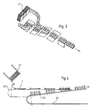
- a blank 1 is removed from a storage magazine 21 (FIGS. 3 and 4) and placed on a transport device 22.
- This transport device 22 is equipped with drivers 23, which ensure a precisely positioned take of the blanks.
- a further transport device 24 is arranged offset from this transport device 22, which runs at an acute angle to the first transport device and is equipped with plungers 25 pointing upwards. When the two transport devices approach each other, these plungers 25 engage in the holes 3 from below and press the tabs 5 and 11 upward.
- the side walls 7 and 8 are simultaneously folded down.
- the cup-shaped objects 4 are positioned over the plungers 25 and then placed on them by means of a feed device 26. Then both are conveyed horizontally, while the carton blank 1 is transported rising upwards and is thus removed from the area of the ram 25 and brought into the area of the objects 4.
- the tabs 5 and 11 remain in their upward bent position.
- guide devices 27 and 28 are arranged on the side of the transport devices, which act on the bottom flaps 18 and 19 and fold them over one another until they rest on the bottoms of the objects 4.
- a glue nozzle 29 is also provided, which injects an adhesive onto the inside of the bottom flap 12, which in the closed state lies on the outside of the closure seam 30.
- a wheel is provided as a pressing device 31, over which the finished carrier is guided.
- FIG. 9 schematically shows a folding device 32 which has two branches running parallel to one another, one of which is provided for two supports arranged one above the other and the other for only one support. Both branches have a supply stack for cardboard blanks 33 and 34, respectively, which are placed on the carriers from above. In the further course these cardboard blanks are then folded around the carrier and closed on the underside.
Landscapes
- Engineering & Computer Science (AREA)
- Mechanical Engineering (AREA)
- Making Paper Articles (AREA)
- Load-Engaging Elements For Cranes (AREA)
- Supplying Of Containers To The Packaging Station (AREA)
- Holding Or Fastening Of Disk On Rotational Shaft (AREA)
- Packages (AREA)
- Closing Of Containers (AREA)
Abstract
Description
- Die Erfindung betrifft eine Vorrichtung zum Aufrichten eines Trägers aus einem flachliegenden Zuschnitt aus Karton od. dgl. für becher- bzw. dosenförmige Gegenstände, die in Löchern einer Tragplatte des Trägers stecken, an der nach oben abstehende, an der Außenseite der Gegenstände anliegende Lappen angeformt sind.
- Der Erfindung liegt die Aufgabe zugrunde, eine Vorrichtung zu schaffen, mit der auf einfache und rationelle Weise ein derartiger Träger aufgerichtet und mit Gegenständen bestückt werden kann.
- Diese Aufgabe wird erfindungsgemäß dadurch gelöst, daß eine im wesentlichen horizontal verlaufende Transporteinrichtung für den Karton-Zuschnitt vorgesehen ist, zu der in einem spitzen Winkel eine weitere Transporteinrichtung verläuft, die nach oben gerichtete Stößel trägt, welche in die Löcher der Tragplatte des Träger-Zuschnittes einzugreifen vermögen.
- Dadurch wird auf einfache Weise der Zuschnitt zum Einsetzen der Gegenstände vorbereitet.
- Sehr vorteilhaft ist es dabei, wenn gemäß einer weiteren Ausgestaltung der Erfindung oberhalb der beiden Transporteinrichtungen eine Zufuhreinrichtung für die becher- bzw. dosenförmigen Gegenstände vorgesehen ist, mit deren Hilfe die Gegenstände auf die von unten durch die Löcher der Tragplatte gesteckten Stößel aufgesetzt werden können, wobei die Stößel wenigstens annähernd die gleiche Querschnittsform aufweisen wie die Böden der Gegenstände und wenn darüber hinaus im weiteren Verlauf der Transport- und Zufuhreinrichtungen diese derart zueinander verlaufen, daß die Stößel aus den Löchern herausgefahren und gleichzeitig die Gegenstände in die Löcher hineingefahren werden.
- Damit ist das Einsetzen der Gegenstände in die Tragplatte völlig automatisiert.
- Eine ebenfalls sehr vorteilhafte Ausgestaltung der Erfindung liegt darin, daß im Anschluß an die zusammenlaufenden Transport- und Zufuhreinrichtungen Leiteinrichtungen vorgesehen sind, welche nach unten abstehende Bodenklappen des Trägers gegeneinanderfalten.
Damit läuft auch das Fertigaufrichten des Trägers auf der gleichen Vorrichtung vollautomatisch ab. - Bei einer ebenfalls vorteilhaften Ausgestaltung der Erfindung ist am Anfang der Leiteinrichtungen eine Leimdüse vorgesehen, die ein Klebemittel auf die Innenseite der einen Bodenklappe spritzt, welche beim Zusammenfalten außen liegt.
- Sehr vorteilhaft ist es auch, wenn erfindungsgemäß an der Unterseite der Einrichtungen eine Preßvorrichtung vorgesehen ist, welche die beiden übereinandergefalteten Bodenklappen zusammenpreßt.
- Eine weitere vorteilhafte Ausgestaltung liegt erfindungsgemäß darin, daß eine Faltvorrichtung vorgesehen ist, mit deren Hilfe um den mit den Gegenständen bestückten Träger eine hülsenförmige Umverpackung geschlagen werden kann.
- In der Zeichnung ist die Erfindung anhand eines Ausführungsbeispiels veranschaulicht. Dabei zeigen:
- Fig. 1 einen flachliegenden Kartonzuschnitt zum Aufrichten eines Trägers für becherförmige Gegenstände,
- Fig. 2 einen fertig aufgerichteten Träger mit becherförmigen Gegenständen bestückt,
- Fig. 3 ein schematisiertes Schaubild einer Einrichtung zum Bestücken des Trägers mit den Gegenständen,
- Fig. 4 eine schematische Ansicht einer Vorrichtung zum Öffnen der Löcher der Tragplatte des Trägers,
- Fig. 5 eine Ansicht einer Vorrichtung zum Einsetzen der Gegenstände in die Löcher der Tragplatte,
- Fig. 6 einen Schnitt durch die Vorrichtung gemäß Fig. 4 entlang der Linie V-V,
- Fig.7+8 zwei Ansichten einer Vorrichtung zum Verschließen der Bodenklappen des Trägers und
- Fig. 9 eine schematische Ansicht einer Vorrichtung zum Anbringen einer hülsenförmigen Umverpackung an wahlweise einem oder zwei übereinander angeordneten Trägern.
- Mit 1 ist in Fig. 1 ein Kartonzuschnitt bezeichnet, der eine Tragplatte 2 aufweist, in welcher Löcher 3 zur Aufnahme von becherförmigen Gegenständen 4 vorgesehen sind. In die Löcher 3 ragen Lappen 5 hinein, die über eine Faltlinie 6 an der Tragplatte 2 angelenkt sind. Ebenfalls an der Tragplatte 2 sind zwei Seitenwände 7 und 8 über Faltlinien 9 und 10 angelenkt. An diesen Seitenwänden 7 und 8 sind Lappen 11 angeformt, die über die beiden Faltlinien 9 bzw. 10 hinaus in die Löcher 3 hineinragen. Die beiden anderen Kanten der Tragplatte 2 sind über Faltlinien 12,13 mit weiteren Seitenwänden 14 und 15 und diese wiederum über Faltlinien 16,17 mit Bodenklappen 18,19 verbunden.
- In Fig. 2 ist ein Träger 20 dargestellt, der fertig aufgerichtet, am Boden verschlossen und mit becherförmigen Gegenständen 4 bestückt ist. Dabei sind die Lappen 5 und die an den Seitenwänden 7 und 8 angeformten Lappen 11 nach oben bis zur Anlage an der Außenseite der Gegenstände 4 abgebogen.
- Zum Aufrichten des Trägers 20 wird einem Vorratsmagazin 21 (Fig. 3 und 4) jeweils ein Zuschnitt 1 entnommen und auf einer Transporteinrichtung 22 abgelegt. Diese Transporteinrichtung 22 ist mit Mitnehmern 23 ausgerüstet, welche ein genau positioniertes Mitnehmen der Zuschnitte gewährleisten. Versetzt zu dieser Transporteinrichtung 22 ist eine weitere Transporteinrichtung 24 angeordnet, welche in einem spitzen Winkel zur ersten Transporteinrichtung verläuft und mit nach oben gerichteten Stößeln 25 ausgerüstet ist. Diese Stößel 25 greifen beim Annähern der beiden Transporteinrichtungen in die Löcher 3 von unten ein und drücken die Lappen 5 und 11 nach oben. Dabei werden gleichzeitig die Seitenwände 7 und 8 nach unten gefaltet.
- Wie aus Fig. 5 ersichtlich, werden taktgleich über eine Zufuhreinrichtung 26 die becherförmigen Gegenstände 4 über den Stößeln 25 positioniert und dann auf diese aufgesetzt. Daraufhin werden beide horizontal weiterbefördert, während der Kartonzuschnitt 1 nach oben ansteigend transportiert wird und so aus dem Bereich der Stößel 25 entfernt und in den Bereich der Gegenstände 4 gebracht wird. Die Lappen 5 und 11 verbleiben dabei in ihrer nach oben abgebogenen Stellung.
- In der Fig. 6 ist der Kartonzuschnitt 1 noch im Bereich der Stößel 25 dargestellt, wobei die nach oben abgebogenen Lappen 11 mit der daran angeformten Seitenwand 7 sichtbar sind.
- Wie in den Fig. 7 und 8 dargestellt, sind seitlich der Transporteinrichtungen Leiteinrichtungen 27 und 28 angeordnet, welche an den Bodenklappen 18 und 19 angreifen und diese bis zur Anlage an den Böden der Gegenstände 4 übereinanderfalten. Zusätzlich ist noch eine Leimdüse 29 vorgesehen, welche ein Klebemittel auf die Innenseite der Bodenklappe 12 spritzt, welche in verschlossenem Zustand auf der Außenseite der Verschlußnaht 30 liegt. Zum Verpressen dieser Verschlußnaht 30 ist als Preßvorrichtung 31 ein Rad vorgesehen, über welches der fertige Träger geführt wird.
- In Fig. 9 ist eine Faltvorrichtung 32 schematisch dargestellt, die zwei parallel zueinander verlaufende Zweige aufweist, von denen der eine für zwei übereinander angeordnete Träger und der andere für nur einen Träger vorgesehen ist. Beide Zweige weisen einen Vorratsstapel für Kartonzuschnitte 33 bzw. 34 auf, die von oben auf die Träger aufgesetzt werden. Im weiteren Verlauf werden diese Kartonzuschnitte dann um die Träger herumgefaltet und an der Unterseite verschlossen.
Claims (6)
Priority Applications (1)
| Application Number | Priority Date | Filing Date | Title |
|---|---|---|---|
| AT88117975T ATE74089T1 (de) | 1987-10-31 | 1988-10-28 | Vorrichtung zum aufrichten eines traegers. |
Applications Claiming Priority (2)
| Application Number | Priority Date | Filing Date | Title |
|---|---|---|---|
| DE3737034 | 1987-10-31 | ||
| DE19873737034 DE3737034A1 (de) | 1987-10-31 | 1987-10-31 | Vorrichtung zum aufrichten eines traegers |
Publications (2)
| Publication Number | Publication Date |
|---|---|
| EP0315065A1 true EP0315065A1 (de) | 1989-05-10 |
| EP0315065B1 EP0315065B1 (de) | 1992-03-25 |
Family
ID=6339541
Family Applications (1)
| Application Number | Title | Priority Date | Filing Date |
|---|---|---|---|
| EP88117975A Expired - Lifetime EP0315065B1 (de) | 1987-10-31 | 1988-10-28 | Vorrichtung zum Aufrichten eines Trägers |
Country Status (5)
| Country | Link |
|---|---|
| EP (1) | EP0315065B1 (de) |
| AT (1) | ATE74089T1 (de) |
| DE (2) | DE3737034A1 (de) |
| ES (1) | ES2031210T3 (de) |
| PT (1) | PT88901B (de) |
Citations (3)
| Publication number | Priority date | Publication date | Assignee | Title |
|---|---|---|---|---|
| US3032945A (en) * | 1959-02-05 | 1962-05-08 | Container Corp | Can packing apparatus |
| EP0024451A1 (de) * | 1979-08-29 | 1981-03-11 | Certipak Corporation | Vorrichtung zum Aufbringen eines hüllenförmigen Trägers |
| EP0149351A2 (de) * | 1983-12-19 | 1985-07-24 | The Mead Corporation | Verpackungsmaschine und -verfahren |
-
1987
- 1987-10-31 DE DE19873737034 patent/DE3737034A1/de active Granted
-
1988
- 1988-10-28 AT AT88117975T patent/ATE74089T1/de active
- 1988-10-28 EP EP88117975A patent/EP0315065B1/de not_active Expired - Lifetime
- 1988-10-28 ES ES198888117975T patent/ES2031210T3/es not_active Expired - Lifetime
- 1988-10-28 DE DE8888117975T patent/DE3869553D1/de not_active Expired - Fee Related
- 1988-10-28 PT PT88901A patent/PT88901B/pt active IP Right Grant
Patent Citations (3)
| Publication number | Priority date | Publication date | Assignee | Title |
|---|---|---|---|---|
| US3032945A (en) * | 1959-02-05 | 1962-05-08 | Container Corp | Can packing apparatus |
| EP0024451A1 (de) * | 1979-08-29 | 1981-03-11 | Certipak Corporation | Vorrichtung zum Aufbringen eines hüllenförmigen Trägers |
| EP0149351A2 (de) * | 1983-12-19 | 1985-07-24 | The Mead Corporation | Verpackungsmaschine und -verfahren |
Also Published As
| Publication number | Publication date |
|---|---|
| EP0315065B1 (de) | 1992-03-25 |
| PT88901A (pt) | 1989-09-14 |
| DE3737034C2 (de) | 1989-08-10 |
| PT88901B (pt) | 1993-12-31 |
| DE3737034A1 (de) | 1989-05-11 |
| DE3869553D1 (de) | 1992-04-30 |
| ATE74089T1 (de) | 1992-04-15 |
| ES2031210T3 (es) | 1992-12-01 |
Similar Documents
| Publication | Publication Date | Title |
|---|---|---|
| EP0117974B1 (de) | Verfahren und Vorrichtung zum Herstellen von Sammelpackungen | |
| EP3450332B1 (de) | Verpackungsvorrichtung für artikel und verfahren zum einbringen von artikeln in vorbereitete umverpackungen | |
| WO2023030718A1 (de) | Verpackungsvorrichtung, verpackungseinheit und verfahren zur herstellung von verpackungseinheiten | |
| DE3421261A1 (de) | Vorrichtung zum falten und verschliessen der stirnwaende von tray-kartons | |
| EP0172133B1 (de) | Verpackung bestehend aus einem Schachtelkörper und Verfahren zum Zusammenbauen und Füllen der Verpackung | |
| DE1586565C3 (de) | Verfahren zum Strammziehen eines eine Behältergruppe schlauchförmig umhüllenden Pappezuschnittes sowie Vorrichtung zur Ausübung dieses Verfahrens | |
| DE2417722A1 (de) | Vorrichtung zur herstellung eines gefalteten kartons | |
| DE102017201842A1 (de) | Handhabungsvorrichtung und Verfahren zum Verschließen von äußeren Bodenlaschen einer Umverpackung | |
| EP0315065B1 (de) | Vorrichtung zum Aufrichten eines Trägers | |
| EP0171703B1 (de) | Trageverpackung aus einem Kartonzuschnitt und Verfahren und Vorrichtung zum Aufrichten dieser Trageverpackung | |
| EP3587291B1 (de) | Verfahren zum herstellen einer verpackungseinheit, umverpackung sowie verpackungseinheit mit einer solchen umverpackung | |
| DE2612458A1 (de) | Verfahren nebst vorrichtung zum aufrichten und verkleben von zunaechst ebenen, vorgefalzten kartonzuschnitten o.dgl. und zum verpacken von behaeltern in den entstehenden kartons o.dgl. | |
| DE4230927A1 (de) | Verfahren und vorrichtung zum aufrichten eines mit handgriffverriegelung versehenen verpackungskartons | |
| DE4100783A1 (de) | Verfahren und vorrichtung zum aufrichten einer verpackung und zuschnitt zum herstellen dieser verpackung | |
| DE2139884C3 (de) | Vorrichtung zum Handhaben von aus Kartonzuschnitten herstellbaren Faltbehältern | |
| DE3241267C2 (de) | Streckfilm-Verpackungsvorrichtung | |
| AT385467B (de) | Verfahren und vorrichtung zum loesbaren verbinden von verpackungskartons fuer getraenkebecher u.dgl. | |
| DE102022115414A1 (de) | Verfahren und Verpackungsvorrichtung zur Herstellung von Verpackungseinheiten sowie Umreifungskopf zur jeweiligen Verwendung hierbei | |
| DE102022115413A1 (de) | Verfahren und Verpackungsvorrichtung zur Herstellung von Verpackungseinheiten sowie Applikationskopf zur jeweiligen Verwendung hierbei | |
| EP0396893A1 (de) | Verpackung aus Karton od.dgl. | |
| EP4112486A1 (de) | Verpackungsmagazin für einen manipulator und verpackungssystem zum herstellen von gebinden | |
| EP4082922A1 (de) | Verpackungsverfahren zur verpackung von primärverpackungen in sekundärverpackungen und verpackungsmodul | |
| DE10255503A1 (de) | Verfahren und Vorrichtung zum Aufrichten von Zuschnitten für Kartons | |
| EP0356888A1 (de) | Verfahren und Vorrichtung zum Aufrichten einer Verpackung | |
| DE2513762A1 (de) | Einstueckiger karton und verfahren zum schliessen des kartons |
Legal Events
| Date | Code | Title | Description |
|---|---|---|---|
| PUAI | Public reference made under article 153(3) epc to a published international application that has entered the european phase |
Free format text: ORIGINAL CODE: 0009012 |
|
| AK | Designated contracting states |
Kind code of ref document: A1 Designated state(s): AT BE CH DE ES FR GB GR IT LI NL SE |
|
| 17P | Request for examination filed |
Effective date: 19891107 |
|
| 17Q | First examination report despatched |
Effective date: 19901025 |
|
| GRAA | (expected) grant |
Free format text: ORIGINAL CODE: 0009210 |
|
| AK | Designated contracting states |
Kind code of ref document: B1 Designated state(s): AT BE CH DE ES FR GB GR IT LI NL SE |
|
| PG25 | Lapsed in a contracting state [announced via postgrant information from national office to epo] |
Ref country code: IT Free format text: LAPSE BECAUSE OF FAILURE TO SUBMIT A TRANSLATION OF THE DESCRIPTION OR TO PAY THE FEE WITHIN THE PRESCRIBED TIME-LIMIT;WARNING: LAPSES OF ITALIAN PATENTS WITH EFFECTIVE DATE BEFORE 2007 MAY HAVE OCCURRED AT ANY TIME BEFORE 2007. THE CORRECT EFFECTIVE DATE MAY BE DIFFERENT FROM THE ONE RECORDED. Effective date: 19920325 Ref country code: GR Free format text: LAPSE BECAUSE OF FAILURE TO SUBMIT A TRANSLATION OF THE DESCRIPTION OR TO PAY THE FEE WITHIN THE PRESCRIBED TIME-LIMIT Effective date: 19920325 Ref country code: NL Effective date: 19920325 Ref country code: SE Effective date: 19920325 Ref country code: GB Effective date: 19920325 |
|
| REF | Corresponds to: |
Ref document number: 74089 Country of ref document: AT Date of ref document: 19920415 Kind code of ref document: T |
|
| REF | Corresponds to: |
Ref document number: 3869553 Country of ref document: DE Date of ref document: 19920430 |
|
| REG | Reference to a national code |
Ref country code: CH Ref legal event code: PUE Owner name: 4P NICOLAUS KEMPTEN GMBH |
|
| RAP2 | Party data changed (patent owner data changed or rights of a patent transferred) |
Owner name: 4P NICOLAUS KEMPTEN GMBH |
|
| ET | Fr: translation filed | ||
| NLV1 | Nl: lapsed or annulled due to failure to fulfill the requirements of art. 29p and 29m of the patents act | ||
| GBV | Gb: ep patent (uk) treated as always having been void in accordance with gb section 77(7)/1977 [no translation filed] | ||
| PG25 | Lapsed in a contracting state [announced via postgrant information from national office to epo] |
Ref country code: AT Effective date: 19921028 |
|
| PG25 | Lapsed in a contracting state [announced via postgrant information from national office to epo] |
Ref country code: LI Effective date: 19921031 Ref country code: CH Effective date: 19921031 |
|
| REG | Reference to a national code |
Ref country code: ES Ref legal event code: FG2A Ref document number: 2031210 Country of ref document: ES Kind code of ref document: T3 |
|
| PLBE | No opposition filed within time limit |
Free format text: ORIGINAL CODE: 0009261 |
|
| STAA | Information on the status of an ep patent application or granted ep patent |
Free format text: STATUS: NO OPPOSITION FILED WITHIN TIME LIMIT |
|
| 26N | No opposition filed | ||
| REG | Reference to a national code |
Ref country code: CH Ref legal event code: PL |
|
| PG25 | Lapsed in a contracting state [announced via postgrant information from national office to epo] |
Ref country code: DE Effective date: 19930701 |
|
| PGFP | Annual fee paid to national office [announced via postgrant information from national office to epo] |
Ref country code: ES Payment date: 19981016 Year of fee payment: 11 |
|
| PGFP | Annual fee paid to national office [announced via postgrant information from national office to epo] |
Ref country code: FR Payment date: 19981026 Year of fee payment: 11 |
|
| PG25 | Lapsed in a contracting state [announced via postgrant information from national office to epo] |
Ref country code: ES Free format text: LAPSE BECAUSE OF NON-PAYMENT OF DUE FEES Effective date: 19991029 |
|
| PG25 | Lapsed in a contracting state [announced via postgrant information from national office to epo] |
Ref country code: FR Free format text: LAPSE BECAUSE OF NON-PAYMENT OF DUE FEES Effective date: 20000630 |
|
| REG | Reference to a national code |
Ref country code: FR Ref legal event code: ST |
|
| PGFP | Annual fee paid to national office [announced via postgrant information from national office to epo] |
Ref country code: BE Payment date: 20001108 Year of fee payment: 13 |
|
| PG25 | Lapsed in a contracting state [announced via postgrant information from national office to epo] |
Ref country code: BE Free format text: LAPSE BECAUSE OF NON-PAYMENT OF DUE FEES Effective date: 20011031 |
|
| BERE | Be: lapsed |
Owner name: 4P EMBALLAGES FRANCE Effective date: 20011031 |
|
| REG | Reference to a national code |
Ref country code: ES Ref legal event code: FD2A Effective date: 20001113 |