EP0315030A1 - Tube laser - Google Patents
Tube laser Download PDFInfo
- Publication number
- EP0315030A1 EP0315030A1 EP88117773A EP88117773A EP0315030A1 EP 0315030 A1 EP0315030 A1 EP 0315030A1 EP 88117773 A EP88117773 A EP 88117773A EP 88117773 A EP88117773 A EP 88117773A EP 0315030 A1 EP0315030 A1 EP 0315030A1
- Authority
- EP
- European Patent Office
- Prior art keywords
- mirror
- mirrors
- laser
- laser tube
- tube
- Prior art date
- Legal status (The legal status is an assumption and is not a legal conclusion. Google has not performed a legal analysis and makes no representation as to the accuracy of the status listed.)
- Withdrawn
Links
Images

Classifications
-
- H—ELECTRICITY
- H01—ELECTRIC ELEMENTS
- H01S—DEVICES USING THE PROCESS OF LIGHT AMPLIFICATION BY STIMULATED EMISSION OF RADIATION [LASER] TO AMPLIFY OR GENERATE LIGHT; DEVICES USING STIMULATED EMISSION OF ELECTROMAGNETIC RADIATION IN WAVE RANGES OTHER THAN OPTICAL
- H01S3/00—Lasers, i.e. devices using stimulated emission of electromagnetic radiation in the infrared, visible or ultraviolet wave range
- H01S3/02—Constructional details
- H01S3/03—Constructional details of gas laser discharge tubes
- H01S3/034—Optical devices within, or forming part of, the tube, e.g. windows, mirrors
-
- Y—GENERAL TAGGING OF NEW TECHNOLOGICAL DEVELOPMENTS; GENERAL TAGGING OF CROSS-SECTIONAL TECHNOLOGIES SPANNING OVER SEVERAL SECTIONS OF THE IPC; TECHNICAL SUBJECTS COVERED BY FORMER USPC CROSS-REFERENCE ART COLLECTIONS [XRACs] AND DIGESTS
- Y10—TECHNICAL SUBJECTS COVERED BY FORMER USPC
- Y10S—TECHNICAL SUBJECTS COVERED BY FORMER USPC CROSS-REFERENCE ART COLLECTIONS [XRACs] AND DIGESTS
- Y10S359/00—Optical: systems and elements
- Y10S359/90—Methods
Definitions
- the present invention relates to a laser tube with a housing tube made of glass or ceramic, with at least one metal mirror holder and with integrated mirrors.
- a laser tube is known from DE-PS 25 06 707.
- the mirrors are used in mirror mounts and hermetically sealed by means of glass solder, the mirror mounts being adapted to the mirrors in terms of their temperature expansion coefficient.
- This requires a relatively expensive material for the mirror mounts and a complicated structure, since a transition from the mirror holder to the front end plate of the laser must be formed, the temperature of the end plate being adapted to the laser housing, that is to say made of a different material, than the mirror version.
- the object on which the present invention is based is to reduce the complexity of such a mirror holder without having to accept a deterioration in the laser power.
- a particularly high-grade silver-filled epoxy resin is suitable for gluing on the mirror.
- a particularly compact structure results from the fact that the laser tube is closed off with a metal face plate, the temperature expansion coefficient of which is adapted to that of the housing tube, and by a fully reflecting mirror being soldered or glued to the face plate inside the laser tube.
- Such a mirror advantageously has a square surface.
- the square surface is preferably square. But it can also have other square shapes, such as Rectangular shape, trapezoidal shape.
- a plasma ashing system contains a high-frequency chamber with a high-frequency coil, through which an ion plasma is generated in an oxygen atmosphere, which then burns the photoresist without residue.
- An advantageous method for adjusting the mirror of a laser tube with 2 integrated mirrors is that after assembly, a measuring beam with a wavelength is radiated into the laser tube which is only partially reflected by the mirrors and that after the reflections of the measuring beam on the mirror surfaces both mirrors can be adjusted.
- the beam of a green helium-neon laser is advantageously used to adjust a red helium-neon laser.
- This method is particularly suitable for adjustment in cases in which a mirror is glued to a metal plate, since in these cases the measuring beam can only be irradiated into the laser from one side and because a measuring beam fully reflected by the mirrors is passed through the first mirror would hardly pass through, so that the adjustment of the second mirror, which is not visible from the outside, would practically no longer be possible.
- a housing tube 1 made of glass or ceramic is closed on one side with a metal cap 2.
- the metal cap 2 has the same coefficient of thermal expansion as the laser tube 1.
- a tube 3 is inserted into the metal cap 2, which consists of an inexpensive material. Examples of suitable materials are copper or steel.
- the tube 3 is flared at the end facing away from the metal cap 2 and serves as a mirror holder for the mirror 6.
- the mirror 6 is by means of an adhesive 4 or one Solder connected vacuum-tight with the tube 3.
- Low-gassing adhesives are suitable as adhesive 4, preferably epoxy resins filled to a high degree with silver.
- Such an adhesive also has a high thermal conductivity and thus enables heat transfer from the mirror to the flange 7 of the tube 3.
- the inclination of the mirror 6 can be adjusted by deforming the tube 3 in the bead 5.
- an end plate 9 serves as a mirror holder, to which a mirror 8 is also glued by means of an adhesive 4.
- the end plate 9 consists of a material whose temperature expansion coefficient is matched to that of the housing tube 1.
- the adhesive 4 has sufficient elasticity so that the mirror 8 does not become detached or deformed even when the temperature fluctuations are to be expected. This is also favored by the support of the mirror 8 on the metal plate, which means that the mirror 8 can be kept very thin on the one hand, since it is not exposed to the vacuum pressure, and on the other hand can have a very small area that only needs to correspond to the beam diameter.
- the connection between the end plate 9 and the housing tube 1 can also be formed by an adhesive of the type described, but it can also be carried out using soft soldering technology. In both cases, the temperature load on the adhesive 4 on the mirror 8 is kept sufficiently low.
- the mirror 8 can be mounted on the end plate 9 precisely lying parallel, so that it is generally sufficient to align the end plate 9 exactly perpendicular to the discharge channel 23.
- an adjusting bolt 10 is attached, which enables the end plate 9 to bend slightly. If necessary, the adjustment bolt 10 can be surrounded by an annular zone 11 with a small wall thickness in order to improve the flexibility of the end plate 9.
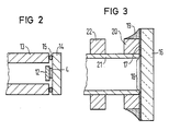
- FIG. 2 shows an attachment of a mirror 12 by means of an adhesive 4 to a metal plate 14, the metal plate 14 being soldered to a metal tube 13 by means of a solder ring 15.
- This embodiment enables the use of particularly small mirrors in connection with a mirror holder of a conventional type. It also has the advantage that the metal tube 13 and the metal plate 14 can be made of cheap material.
- the adhesive point on the mirror 12 here is particularly small, so that the remaining tension is kept particularly low.
- FIG. 3 shows an embodiment in which a mirror 16 is coated with a solderable metal layer 17, the metal layer 17 leaving a beam passage area 18 free.
- the metal layer 17 is soldered to a ring 20 made of metal via a solder 19.
- the ring 20 is firmly seated on a relatively thin metal tube 21.
- a further ring 22 is fastened on the metal tube 21 at a short distance.
- the rings 20 and 22 can advantageously be soldered to the metal tube 21; in many cases, however, pressing the rings 20, 22 onto the metal tube 21 is sufficient.
- the rings 20 and 22 and the metal tube are advantageously made of copper. This material can be soldered well and is ductile, so that a bending of the tube 21 in the area between the two rings 20 and 22 for adjusting the mirror is possible without difficulty.
- This embodiment allows a particularly small dimensioning of the holder.
- the ring 20 can be connected in one piece to the tube 21. In this case, it is advisable to produce this combined part by an extrusion process.
Applications Claiming Priority (2)
| Application Number | Priority Date | Filing Date | Title |
|---|---|---|---|
| DE3737626 | 1987-11-05 | ||
| DE3737626 | 1987-11-05 |
Publications (1)
| Publication Number | Publication Date |
|---|---|
| EP0315030A1 true EP0315030A1 (fr) | 1989-05-10 |
Family
ID=6339880
Family Applications (1)
| Application Number | Title | Priority Date | Filing Date |
|---|---|---|---|
| EP88117773A Withdrawn EP0315030A1 (fr) | 1987-11-05 | 1988-10-25 | Tube laser |
Country Status (2)
| Country | Link |
|---|---|
| US (2) | US4943972A (fr) |
| EP (1) | EP0315030A1 (fr) |
Cited By (2)
| Publication number | Priority date | Publication date | Assignee | Title |
|---|---|---|---|---|
| EP0432618A2 (fr) * | 1989-12-12 | 1991-06-19 | Carl Zeiss | Télescope à miroir |
| EP0477421A1 (fr) * | 1990-09-28 | 1992-04-01 | Siemens Aktiengesellschaft | Support pour miroir d'un laser à gaz |
Families Citing this family (2)
| Publication number | Priority date | Publication date | Assignee | Title |
|---|---|---|---|---|
| DE59005232D1 (de) * | 1989-05-31 | 1994-05-11 | Siemens Ag | Gaslaser. |
| US7787505B1 (en) | 2006-12-08 | 2010-08-31 | Research Electro-Optics, Inc. | Multi-longitudinal mode laser providing polarization control |
Citations (6)
| Publication number | Priority date | Publication date | Assignee | Title |
|---|---|---|---|---|
| US3790900A (en) * | 1971-11-29 | 1974-02-05 | Siemens Ag | Gas laser mirror assembly |
| US3851275A (en) * | 1972-09-07 | 1974-11-26 | Nippon Electric Co | Mirror support structure for an internal mirror-type gas laser tube |
| US3857161A (en) * | 1973-02-09 | 1974-12-31 | T Hutchins | Method of making a ductile hermetic indium seal |
| US4081762A (en) * | 1975-02-18 | 1978-03-28 | Siemens Aktiengesellschaft | Gas laser with a laser capillary positioned in a discharge tube |
| US4216438A (en) * | 1976-12-06 | 1980-08-05 | Taizo Oikado | Internal mirror type gas laser tube |
| US4250467A (en) * | 1977-11-09 | 1981-02-10 | Sony Corporation | Gas laser |
Family Cites Families (12)
| Publication number | Priority date | Publication date | Assignee | Title |
|---|---|---|---|---|
| US3555450A (en) * | 1968-01-22 | 1971-01-12 | Laser Associates | Laser window having a metallic frame arranged to permit post optical grinding and polishing |
| US3777281A (en) * | 1970-08-03 | 1973-12-04 | U Hochuli | Seal and method of making same |
| US4233568A (en) * | 1975-02-24 | 1980-11-11 | Xerox Corporation | Laser tube mirror assembly |
| US4153317A (en) * | 1977-12-02 | 1979-05-08 | The Singer Company | Indium seal for gas laser |
| US4283688A (en) * | 1979-11-26 | 1981-08-11 | The United States Of America As Represented By The Secretary Of The Air Force | Laser autoalignment system |
| DE3470980D1 (en) * | 1983-02-17 | 1988-06-09 | Siemens Ag | Gas laser and method of making the same |
| DE3480250D1 (en) * | 1983-03-30 | 1989-11-23 | Siemens Ag | Gas laser discharge tube |
| US4575853A (en) * | 1983-12-30 | 1986-03-11 | Jako Geza J | Sealed laser |
| US4963012A (en) * | 1984-07-20 | 1990-10-16 | The United States Of America As Represented By The United States Department Of Energy | Passivation coating for flexible substrate mirrors |
| US4677640A (en) * | 1985-09-24 | 1987-06-30 | Spectra-Physics, Inc. | Crystalline quartz laser window assembly |
| FR2593649B1 (fr) * | 1986-01-27 | 1988-05-20 | Asulab Sa | Laser a gaz scelle. |
| FR2595875B1 (fr) * | 1986-03-17 | 1989-02-17 | Asulab Sa | Laser comportant au moins un joint d'etancheite |
-
1988
- 1988-10-25 EP EP88117773A patent/EP0315030A1/fr not_active Withdrawn
- 1988-11-02 US US07/265,932 patent/US4943972A/en not_active Expired - Lifetime
-
1990
- 1990-02-06 US US07/475,998 patent/US5044731A/en not_active Expired - Fee Related
Patent Citations (6)
| Publication number | Priority date | Publication date | Assignee | Title |
|---|---|---|---|---|
| US3790900A (en) * | 1971-11-29 | 1974-02-05 | Siemens Ag | Gas laser mirror assembly |
| US3851275A (en) * | 1972-09-07 | 1974-11-26 | Nippon Electric Co | Mirror support structure for an internal mirror-type gas laser tube |
| US3857161A (en) * | 1973-02-09 | 1974-12-31 | T Hutchins | Method of making a ductile hermetic indium seal |
| US4081762A (en) * | 1975-02-18 | 1978-03-28 | Siemens Aktiengesellschaft | Gas laser with a laser capillary positioned in a discharge tube |
| US4216438A (en) * | 1976-12-06 | 1980-08-05 | Taizo Oikado | Internal mirror type gas laser tube |
| US4250467A (en) * | 1977-11-09 | 1981-02-10 | Sony Corporation | Gas laser |
Cited By (4)
| Publication number | Priority date | Publication date | Assignee | Title |
|---|---|---|---|---|
| EP0432618A2 (fr) * | 1989-12-12 | 1991-06-19 | Carl Zeiss | Télescope à miroir |
| EP0432618A3 (en) * | 1989-12-12 | 1991-09-18 | Firma Carl Zeiss | Mirror telescope |
| US5138484A (en) * | 1989-12-12 | 1992-08-11 | Carl-Zeiss-Stiftung | Mirror telescope |
| EP0477421A1 (fr) * | 1990-09-28 | 1992-04-01 | Siemens Aktiengesellschaft | Support pour miroir d'un laser à gaz |
Also Published As
| Publication number | Publication date |
|---|---|
| US4943972A (en) | 1990-07-24 |
| US5044731A (en) | 1991-09-03 |
Similar Documents
| Publication | Publication Date | Title |
|---|---|---|
| DE3138296C2 (fr) | ||
| EP0111264A2 (fr) | Appareil de transmission ou réception pour équipement opto-électrique de communication | |
| EP0149232A2 (fr) | Composant semi-conducteur comprenant un socle métallique | |
| DE3101378A1 (de) | Optik zur ankopplung eines faseroptischen lichtwellenleiters | |
| DE2647934A1 (de) | Gaslaserroehre | |
| EP0214464A1 (fr) | Boîtier pour un module de circuit opto-électronique | |
| DE2612657A1 (de) | Stiftbefestigung fuer laser | |
| DE3318169A1 (de) | Lampeneinheit mit genau angeordnetem faden | |
| EP0315030A1 (fr) | Tube laser | |
| DE10104778B4 (de) | Xenon-Bogenlampe | |
| DE3219582A1 (de) | Elektrische lampe mit einem mechanisch befestigten lampensockel | |
| DE3433717C2 (fr) | ||
| DE3307669C2 (fr) | ||
| EP0119408A2 (fr) | Laser à gaz et procédé pour sa réalisation | |
| DE1934414B2 (de) | Gaslaser mit einem Kaltkathodenentladungsgefäß | |
| DE2834968A1 (de) | Abgedichteter scheinwerfer, insbesondere fuer kraftfahrzeuge, und verfahren zu seiner herstellung | |
| DE3727849A1 (de) | Elektronenkanone und verfahren zu ihrer montage | |
| DE2333033C3 (de) | Verfahren zur Herstellung und Anbringung einer Haltevorrichtung für einen piezoelektrischen Resonator und mit einer solchen Haltevorrichtung versehener Resonator | |
| DE2627042A1 (de) | Vorrichtung zur verbindung von lichtleitfaserkabeln | |
| EP0166029B1 (fr) | Tube pour laser à gaz et son procédé de fabrication | |
| DE2855390C2 (de) | Kolbenanordnung für Projektionsfernsehröhren und deren Herstellung | |
| EP0217084A1 (fr) | Tube de décharge à gaz pour un laser à ions | |
| DE10002329A1 (de) | Herstellungsverfahren für eine optische Sende-Baugruppe | |
| EP0217083A1 (fr) | Tube de décharge refroidi à l'air pour un laser à ions | |
| DE3032172A1 (de) | Lichtaktivierbare halbleitervorrichtung. |
Legal Events
| Date | Code | Title | Description |
|---|---|---|---|
| PUAI | Public reference made under article 153(3) epc to a published international application that has entered the european phase |
Free format text: ORIGINAL CODE: 0009012 |
|
| AK | Designated contracting states |
Kind code of ref document: A1 Designated state(s): DE GB |
|
| 17P | Request for examination filed |
Effective date: 19891106 |
|
| STAA | Information on the status of an ep patent application or granted ep patent |
Free format text: STATUS: THE APPLICATION HAS BEEN WITHDRAWN |
|
| 18W | Application withdrawn |
Withdrawal date: 19910322 |