EP0315030A1 - Laser tube - Google Patents
Laser tube Download PDFInfo
- Publication number
- EP0315030A1 EP0315030A1 EP88117773A EP88117773A EP0315030A1 EP 0315030 A1 EP0315030 A1 EP 0315030A1 EP 88117773 A EP88117773 A EP 88117773A EP 88117773 A EP88117773 A EP 88117773A EP 0315030 A1 EP0315030 A1 EP 0315030A1
- Authority
- EP
- European Patent Office
- Prior art keywords
- mirror
- mirrors
- laser
- laser tube
- tube
- Prior art date
- Legal status (The legal status is an assumption and is not a legal conclusion. Google has not performed a legal analysis and makes no representation as to the accuracy of the status listed.)
- Withdrawn
Links
Images

Classifications
-
- H—ELECTRICITY
- H01—ELECTRIC ELEMENTS
- H01S—DEVICES USING THE PROCESS OF LIGHT AMPLIFICATION BY STIMULATED EMISSION OF RADIATION [LASER] TO AMPLIFY OR GENERATE LIGHT; DEVICES USING STIMULATED EMISSION OF ELECTROMAGNETIC RADIATION IN WAVE RANGES OTHER THAN OPTICAL
- H01S3/00—Lasers, i.e. devices using stimulated emission of electromagnetic radiation in the infrared, visible or ultraviolet wave range
- H01S3/02—Constructional details
- H01S3/03—Constructional details of gas laser discharge tubes
- H01S3/034—Optical devices within, or forming part of, the tube, e.g. windows, mirrors
-
- Y—GENERAL TAGGING OF NEW TECHNOLOGICAL DEVELOPMENTS; GENERAL TAGGING OF CROSS-SECTIONAL TECHNOLOGIES SPANNING OVER SEVERAL SECTIONS OF THE IPC; TECHNICAL SUBJECTS COVERED BY FORMER USPC CROSS-REFERENCE ART COLLECTIONS [XRACs] AND DIGESTS
- Y10—TECHNICAL SUBJECTS COVERED BY FORMER USPC
- Y10S—TECHNICAL SUBJECTS COVERED BY FORMER USPC CROSS-REFERENCE ART COLLECTIONS [XRACs] AND DIGESTS
- Y10S359/00—Optical: systems and elements
- Y10S359/90—Methods
Definitions
- the present invention relates to a laser tube with a housing tube made of glass or ceramic, with at least one metal mirror holder and with integrated mirrors.
- a laser tube is known from DE-PS 25 06 707.
- the mirrors are used in mirror mounts and hermetically sealed by means of glass solder, the mirror mounts being adapted to the mirrors in terms of their temperature expansion coefficient.
- This requires a relatively expensive material for the mirror mounts and a complicated structure, since a transition from the mirror holder to the front end plate of the laser must be formed, the temperature of the end plate being adapted to the laser housing, that is to say made of a different material, than the mirror version.
- the object on which the present invention is based is to reduce the complexity of such a mirror holder without having to accept a deterioration in the laser power.
- a particularly high-grade silver-filled epoxy resin is suitable for gluing on the mirror.
- a particularly compact structure results from the fact that the laser tube is closed off with a metal face plate, the temperature expansion coefficient of which is adapted to that of the housing tube, and by a fully reflecting mirror being soldered or glued to the face plate inside the laser tube.
- Such a mirror advantageously has a square surface.
- the square surface is preferably square. But it can also have other square shapes, such as Rectangular shape, trapezoidal shape.
- a plasma ashing system contains a high-frequency chamber with a high-frequency coil, through which an ion plasma is generated in an oxygen atmosphere, which then burns the photoresist without residue.
- An advantageous method for adjusting the mirror of a laser tube with 2 integrated mirrors is that after assembly, a measuring beam with a wavelength is radiated into the laser tube which is only partially reflected by the mirrors and that after the reflections of the measuring beam on the mirror surfaces both mirrors can be adjusted.
- the beam of a green helium-neon laser is advantageously used to adjust a red helium-neon laser.
- This method is particularly suitable for adjustment in cases in which a mirror is glued to a metal plate, since in these cases the measuring beam can only be irradiated into the laser from one side and because a measuring beam fully reflected by the mirrors is passed through the first mirror would hardly pass through, so that the adjustment of the second mirror, which is not visible from the outside, would practically no longer be possible.
- a housing tube 1 made of glass or ceramic is closed on one side with a metal cap 2.
- the metal cap 2 has the same coefficient of thermal expansion as the laser tube 1.
- a tube 3 is inserted into the metal cap 2, which consists of an inexpensive material. Examples of suitable materials are copper or steel.
- the tube 3 is flared at the end facing away from the metal cap 2 and serves as a mirror holder for the mirror 6.
- the mirror 6 is by means of an adhesive 4 or one Solder connected vacuum-tight with the tube 3.
- Low-gassing adhesives are suitable as adhesive 4, preferably epoxy resins filled to a high degree with silver.
- Such an adhesive also has a high thermal conductivity and thus enables heat transfer from the mirror to the flange 7 of the tube 3.
- the inclination of the mirror 6 can be adjusted by deforming the tube 3 in the bead 5.
- an end plate 9 serves as a mirror holder, to which a mirror 8 is also glued by means of an adhesive 4.
- the end plate 9 consists of a material whose temperature expansion coefficient is matched to that of the housing tube 1.
- the adhesive 4 has sufficient elasticity so that the mirror 8 does not become detached or deformed even when the temperature fluctuations are to be expected. This is also favored by the support of the mirror 8 on the metal plate, which means that the mirror 8 can be kept very thin on the one hand, since it is not exposed to the vacuum pressure, and on the other hand can have a very small area that only needs to correspond to the beam diameter.
- the connection between the end plate 9 and the housing tube 1 can also be formed by an adhesive of the type described, but it can also be carried out using soft soldering technology. In both cases, the temperature load on the adhesive 4 on the mirror 8 is kept sufficiently low.
- the mirror 8 can be mounted on the end plate 9 precisely lying parallel, so that it is generally sufficient to align the end plate 9 exactly perpendicular to the discharge channel 23.
- an adjusting bolt 10 is attached, which enables the end plate 9 to bend slightly. If necessary, the adjustment bolt 10 can be surrounded by an annular zone 11 with a small wall thickness in order to improve the flexibility of the end plate 9.
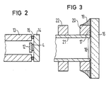
- FIG. 2 shows an attachment of a mirror 12 by means of an adhesive 4 to a metal plate 14, the metal plate 14 being soldered to a metal tube 13 by means of a solder ring 15.
- This embodiment enables the use of particularly small mirrors in connection with a mirror holder of a conventional type. It also has the advantage that the metal tube 13 and the metal plate 14 can be made of cheap material.
- the adhesive point on the mirror 12 here is particularly small, so that the remaining tension is kept particularly low.
- FIG. 3 shows an embodiment in which a mirror 16 is coated with a solderable metal layer 17, the metal layer 17 leaving a beam passage area 18 free.
- the metal layer 17 is soldered to a ring 20 made of metal via a solder 19.
- the ring 20 is firmly seated on a relatively thin metal tube 21.
- a further ring 22 is fastened on the metal tube 21 at a short distance.
- the rings 20 and 22 can advantageously be soldered to the metal tube 21; in many cases, however, pressing the rings 20, 22 onto the metal tube 21 is sufficient.
- the rings 20 and 22 and the metal tube are advantageously made of copper. This material can be soldered well and is ductile, so that a bending of the tube 21 in the area between the two rings 20 and 22 for adjusting the mirror is possible without difficulty.
- This embodiment allows a particularly small dimensioning of the holder.
- the ring 20 can be connected in one piece to the tube 21. In this case, it is advisable to produce this combined part by an extrusion process.
Abstract
Description
Die vorliegende Erfindung betrifft eine Laserröhre mit einem Gehäuserohr aus Glas oder Keramik, mit zumindest einer Metallspiegelhalterung und mit integrierten Spiegeln. Eine derartige Laserröhre ist aus der DE-PS 25 06 707 bekannt. Dort werden die Spiegel in Spiegelfassungen eingesetzt und über Glaslot hermetisch dicht verbunden, wobei die Spiegelfassungen in ihrem Temperaturausdehnungskoeffizienten an die Spiegel angepaßt sind. Hierzu ist ein relativ teures Material für die Spiegelfassungen erforderlich und ein komplizierter Aufbau, da ein Übergang von der Spiegelhalterung zur stirnseitigen Abschlußplatte des Lasers gebildet werden muß, wobei die Abschlußplatte in ihrem Temperaturkoeffizienten an das Lasergehäuse angepaßt ist, also aus einem anderen Werkstoff bestehen muß, als die Spiegelfassung.The present invention relates to a laser tube with a housing tube made of glass or ceramic, with at least one metal mirror holder and with integrated mirrors. Such a laser tube is known from DE-PS 25 06 707. There, the mirrors are used in mirror mounts and hermetically sealed by means of glass solder, the mirror mounts being adapted to the mirrors in terms of their temperature expansion coefficient. This requires a relatively expensive material for the mirror mounts and a complicated structure, since a transition from the mirror holder to the front end plate of the laser must be formed, the temperature of the end plate being adapted to the laser housing, that is to say made of a different material, than the mirror version.
Die Aufgabe, die der vorliegenden Erfindung zugrundeliegt, besteht in einer Herabsetzung des Aufwandes einer derartigen Spiegelhalterung, ohne eine Verschlechterung der Laserleistung in Kauf nehmen zu müssen.The object on which the present invention is based is to reduce the complexity of such a mirror holder without having to accept a deterioration in the laser power.
Diese Aufgabe wird bei einer Laserröhre der oben bechriebenen Art durch die kennzeichnenden Merkmale des Patentanspruchs 1 oder des Patentanspruchs 2 gelöst. Beide Lösungsformen ergeben ausreichend vakuumdichte und dabei elastisch verformbare Verbindungen, die den zu erwartenden Temperaturbeanspruchungen standhalten. Die höchste Temperaturbeanspruchung der entsprechenden Teile tritt erfahrungsgemäß beim Zusammenlöten des Lasers auf. Daher sind die geringen Verbindungstemperaturen der beiden angegebenen Lösungswege besonders vorteilhaft, eine erheblich über den Belastungen im Betriebsfall liegende Temperaturbelastung wird vermieden.This object is achieved in a laser tube of the type described above by the characterizing features of
Zum Aufkleben des Spiegels eignet sich insbesondere ein hochgradig mit Silber gefülltes Epoxidharz.A particularly high-grade silver-filled epoxy resin is suitable for gluing on the mirror.
Ein besonders kompakter Aufbau ergibt sich, indem das Laserrohr mit einer Stirnscheibe aus Metall abgeschlossen ist, deren Temperaturausdehnungskoeffizient an den des Gehäuserohrs angepaßt ist und indem ein vollreflektierender Spiegel im Inneren der Laserröhre auf die Stirnscheibe aufgelötet bzw. aufgeklebt ist.A particularly compact structure results from the fact that the laser tube is closed off with a metal face plate, the temperature expansion coefficient of which is adapted to that of the housing tube, and by a fully reflecting mirror being soldered or glued to the face plate inside the laser tube.
Eine zusätzliche Rationalisierungsmöglichkeit ist gegeben, indem der Spiegel aus einem Mutterspiegel abgetrennt ist. Ein derartiger Spiegel besitzt vorteilhaft eine viereckige Oberfläche. Die viereckige Oberfläche ist vorzugsweise quadratisch. Sie kann aber auch andere Viereckformen besitzen, wie z.B. Rechteckform, Trapezform.An additional rationalization option is given by separating the mirror from a mother mirror. Such a mirror advantageously has a square surface. The square surface is preferably square. But it can also have other square shapes, such as Rectangular shape, trapezoidal shape.
Derartige Laserspiegel werden vorteilhaft durch ein Verfahren mit den folgenden Verfahrensschritten hergestellt:
- a) Ein Mutterspiegel mit der Fläche von mehreren Spiegeln wird mit Fotolack beschichtet,
- b) der Fotolack wird gehärtet,
- c) der Mutterspiegel wird in Spiegel zersägt, wobei die Schnittkanten gleichzeitig mit einer Fase versehen werden,
- d) die Laserspiegel werden gereinigt,
- e) der Fotolack wird in einer Plasmaveraschungsanlage rückstandfrei entfernt.
- a) A mother mirror with the area of several mirrors is coated with photoresist,
- b) the photoresist is hardened,
- c) the mother mirror is sawn into a mirror, the cut edges being provided with a chamfer at the same time,
- d) the laser mirrors are cleaned,
- e) the photoresist is removed without residue in a plasma ashing system.
Eine Plasmaveraschungsanlage enthält eine Hochfrequenzkammer mit einer Hochfrequenzspule, durch die in einer Sauerstoffatmosphäre ein Ionenplasma erzeugt wird, welches dann den Fotolack rückstandfrei verbrennt.A plasma ashing system contains a high-frequency chamber with a high-frequency coil, through which an ion plasma is generated in an oxygen atmosphere, which then burns the photoresist without residue.
Ebenfalls vorteilhaft ist ein Verfahren, bei dem der Mutterspiegel nicht zersägt, sondern geritzt und gebrochen wird und die Kanten der Spiegel mittels Flußsäure verrundet werden, wobei die übrigen Verfahrensschritte des oben genannten Verfahrens beibehalten werden.Also advantageous is a method in which the mother mirror is not sawn but scratched and broken and the edges of the mirrors are rounded off with hydrofluoric acid, the other process steps of the above-mentioned method being retained.
Eine vorteilhafte Methode zur Justierung der Spiegel einer Laserröhre mit 2 integrierten Spiegeln besteht darin, daß nach dem Zusammenbau in die Laserröhre ein Meßstrahl mit einer Wellenlänge eingestrahlt wird, welche von den Spiegeln nur teilweise reflektiert wird und daß nach den Reflexionen des Meßstrahles an den Spiegeloberflächen die beiden Spiegel justiert werden. Dabei wird vorteilhaft zur Justierung eines roten Helium-Neon-Lasers der Strahl eines grünen Helium-Neon-Lasers eingesetzt. Dieses Verfahren eignet sich insbesondere zur Justierung in den Fällen, in denen ein Spiegel auf eine Metallplatte aufgeklebt ist, da in diesen Fällen der Meßstrahl nur von einer Seite in den Laser eingestrahlt werden kann und da ein von den Spiegeln voll reflektierter Meßstrahl durch den ersten Spiegel kaum nennenswert hindurchtreten würde, so daß die Justierung des zweiten, von außen nicht sichtbaren Spiegels praktisch nicht mehr möglich wäre.An advantageous method for adjusting the mirror of a laser tube with 2 integrated mirrors is that after assembly, a measuring beam with a wavelength is radiated into the laser tube which is only partially reflected by the mirrors and that after the reflections of the measuring beam on the mirror surfaces both mirrors can be adjusted. The beam of a green helium-neon laser is advantageously used to adjust a red helium-neon laser. This method is particularly suitable for adjustment in cases in which a mirror is glued to a metal plate, since in these cases the measuring beam can only be irradiated into the laser from one side and because a measuring beam fully reflected by the mirrors is passed through the first mirror would hardly pass through, so that the adjustment of the second mirror, which is not visible from the outside, would practically no longer be possible.
Die Erfindung wird nun anhand von drei Figuren näher erläutert. Sie ist nicht auf die in den Figuren gezeigten Beispiele beschränkt.
- Fig. 1 zeigt eine erfindungsgemäße Laserröhre in geschnittener Ansicht. Die
- Fig. 2 und 3 zeigen weitere Beispiele für die Befestigungsmöglichkeit der Laserspiegel om geschnittener und gebrochener Ansicht.
- Fig. 1 shows a laser tube according to the invention in a sectional view. The
- 2 and 3 show further examples of the possibility of fastening the laser mirror om a cut and broken view.
Ein Gehäuserohr 1 aus Glas oder Keramik ist auf einer Seite mit einer Metallkappe 2 abgeschlossen. Die Metallkappe 2 weist denselben Temperaturausdehnungskoeffizienten auf wie das Laserrohr 1.A
In Richtung des Laserstrahles ist in die Metallkappe 2 ein Rohr 3 eingesetzt, welches aus einem billigen Werkstoff besteht. Als Werkstoffe eignen sich beispielsweise Kupfer oder Stahl. Das Rohr 3 ist an dem von der Metallkappe 2 abgewandten Ende flanschartig aufgeweitet und dient als Spiegelhalterung für den Spiegel 6. Der Spiegel 6 ist mittels eines Klebers 4 oder eines Lotes mit dem Rohr 3 vakuumdicht verbunden. Als Kleber 4 eignen sich wenig gasende Kleber, vorzugsweise hochgradig mit Silber gefüllte Epoxidharze. Ein derartiger Kleber weist auch eine hohe Wärmeleitfähigkeit auf und ermöglicht somit den Wärmeübergang vom Spiegel zum Flansch 7 des Rohres 3. Die Neigung des Spiegels 6 kann durch eine Verformung des Rohres 3 in der Sicke 5 justiert werden. Auf der gegenüberliegenden Seite des Gehäuserohres 1 dient als Spiegelhalterung eine Stirnplatte 9, auf die ein Spiegel 8 ebenfalls mittels eines Klebers 4 aufgeklebt ist. Die Stirnplatte 9 besteht aus einem Material, dessen Temperaturausdehnungskoeffizient an den des Gehäuserohres 1 angepaßt ist. Der Kleber 4 weist genügend Elastizität auf, so daß der Spiegel 8 sich auch bei den zu erwartenden Temperaturschwankungen nicht löst oder verformt. Dies wird auch durch die Unterstützung des Spiegels 8 auf der Metallplatte begünstigt, wodurch der Spiegel 8 einerseits sehr dünn gehalten werden kann, da er dem Vakuumdruck nicht ausgesetzt ist, und andererseits eine sehr kleine Fläche aufweisen darf, die nur dem Strahldurchmesser zu entsprechen braucht. Je dünner und kleinflächiger der Spiegel gestaltet wird, um so besser ist die Wärmeabfuhr über den gut wärmeleitenden Kleber 4 auf die Stirnplatte 9 und umso geringer die Verspannung bei Temperaturschwankungen. Die Verbindung zwischen der Stirnplatte 9 und dem Gehäuserohr 1 kann dabei ebenfalls durch einen Kleber der beschriebenen Art gebildet sein, sie kann aber auch mittels Weichlottechnik durchgeführt sein. In beiden Fällen wird die Temperaturbelastung des Klebers 4 am Spiegel 8 ausreichend gering gehalten.In the direction of the laser beam, a tube 3 is inserted into the metal cap 2, which consists of an inexpensive material. Examples of suitable materials are copper or steel. The tube 3 is flared at the end facing away from the metal cap 2 and serves as a mirror holder for the
Der Spiegel 8 läßt sich auf der Stirnplatte 9 präzise parallel liegend aufbringen, so daß es im allgemeinen genügt, die Stirnplatte 9 zum Entladungskanal 23 exakt senkrecht auszurichten. Für eine zusätzliche nachträgliche Korrektur der Spiegellage ist ein Justierbolzen 10 angebracht, welcher eine geringfügige Verbiegung der Stirnplatte 9 ermöglicht. Bei Bedarf kann zur besseren Verbiegbarkeit der Stirnplatte 9 der Justierbolzen 10 von einer ringförmigen Zone 11 mit geringer Wandstärke umgeben sein.The mirror 8 can be mounted on the end plate 9 precisely lying parallel, so that it is generally sufficient to align the end plate 9 exactly perpendicular to the
Fig. 2 zeigt eine Befestigung eines Spiegels 12 mittels eines Klebers 4 auf einer Metallplatte 14, wobei die Metallplatte 14 mittels eines Lotringes 15 mit einem Metallrohr 13 verlötet ist. Diese Ausführungsform ermöglicht die Verwendung von besonders kleinen Spiegeln in Verbindung mit einer Spiegelhalterung üblicher Bauart. Sie beinhaltet ebenfalls den Vorteil, daß das Metallrohr 13 und die Metallplatte 14 aus billigem Material hergestellt werden können. Die Klebestelle am Spiegel 12 ist hier besonders kleinflächig, sodaß die restlichen Verspannungen besonders gering gehalten werden.2 shows an attachment of a
Fig. 3 zeigt eine Ausführungsform, bei der ein Spiegel 16 mit einer lötfähigen Metallschicht 17 beschichtet ist, wobei die Metallschicht 17 einen Strahldurchtrittsbereich 18 freiläßt. Die Metallschicht 17 ist über ein Lot 19 mit einem Ring 20 aus Metall verlötet. Der Ring 20 sitzt fest auf einem relativ dünnen Metallrohr 21. Ein weiterer Ring 22 ist in geringem Abstand auf dem Metallrohr 21 befestigt. Die Ringe 20 und 22 können vorteilhafterweise auf das Metallrohr 21 aufgelötet sein; in vielen Fällen reicht jedoch ein Aufpressen der Ringe 20, 22 auf das Metallrohr 21 aus. Dabei bestehen vorteilhaft die Ringe 20 und 22 und das Metallrohr aus Kupfer. Dieser Werkstoff läßt sich gut löten und ist duktil, so daß eine Verbiegung des Rohres 21 im Bereich zwischen den beiden Ringen 20 und 22 zur Justierung des Spiegels ohne Schwierigkeiten möglich ist. Diese Ausführungsform läßt eine besonders kleine Dimensionierung der Halterung zu. In einer weiteren Ausbildung der Erfindung kann der Ring 20 mit dem Rohr 21 einstückig verbunden sein. In diesem Fall empfiehlt es sich, dieses kombinierte Teil durch einen Fließpreßprozeß herzustellen.FIG. 3 shows an embodiment in which a
Claims (10)
dadurch gekennzeichnet,
daß die metallische Spiegelhalterung aus einem kostengünstigen, an den Temperaturausdehnungskoeffizienten des Spiegelmateriales nicht angepaßten Material besteht und daß der Spiegel zumindest einen lötbaren Bereich aufweist und mittels Weichlot auf die Spiegelhalterung aufgelötet ist.1. laser tube with a housing tube made of glass-like or ceramic materials, with at least one metallic mirror holder and an integrated mirror,
characterized by
that the metallic mirror holder consists of an inexpensive material which is not adapted to the temperature expansion coefficient of the mirror material and that the mirror has at least one solderable area and is soldered onto the mirror holder by means of soft solder.
dadurch gekennzeichnet,
daß die metallische Spiegelhalterung aus einem kostengünstigen, an den Temperaturausdehnungskoeffizienten des Spiegelmaterials nicht angepaßten Material besteht und daß der Spiegel mittels eines wenig gasenden Klebers aufgeklebt ist.2. laser tube with a housing tube made of a glass-like or ceramic material with at least one metallic mirror holder and an integrated mirror,
characterized by
that the metallic mirror holder consists of an inexpensive material that is not adapted to the temperature expansion coefficient of the mirror material and that the mirror is glued on using a low-gassing adhesive.
dadurch gekennzeichnet,
daß der Spiegel mittels eines hochgradig mit Silber gefüllten Epoxidharzklebers aufgeklebt ist.3. Laser tube according to claim 2,
characterized by
that the mirror is glued on with a highly filled with silver epoxy resin adhesive.
dadurch gekennzeichnet,
daß das Gehäuserohr mit einer Stirnscheibe aus Metall abgeschlossen ist, deren Temperaturausdehnungskoeffizient an den des Gehäuserohres angepaßt ist und daß ein vollreflektierender Spiegel im Inneren der Laserröhre auf diese Stirnscheibe aufgelötet bzw. aufgeklebt ist.4. Laser tube according to one of claims 1 or 2,
characterized by
that the housing tube is closed with a face plate made of metal, the temperature expansion coefficient of which is adapted to that of the housing tube, and that a fully reflecting mirror is soldered or glued to this face plate inside the laser tube.
dadurch gekennzeichnet,
daß der Spiegel aus einem Mutterspiegel abgetrennt ist.5. Laser tube according to one of claims 1 to 4,
characterized by
that the mirror is separated from a mother mirror.
dadurch gekennzeichnet,
daß der Spiegel eine viereckige Oberfläche besitzt.6. laser tube according to claim 5,
characterized by
that the mirror has a square surface.
gekennzeichnet durch
die folgenden Merkmale:
marked by
the following characteristics:
gekennzeichnet durch
die folgenden Merkmale:
marked by
the following characteristics:
dadurch gekennzeichnet,
daß nach dem Zusammenbau in die Laserröhre ein Meßstrahl mit einer Wellenlänge eingestrahlt wird, welche von den Spiegeln nur teilweise reflektiert wird und daß nach den Reflexionen des Meßstrahles an den Spiegeloberflächen die beiden Spiegel justiert werden.9. A method for adjusting the mirror of a laser tube with two mirrors according to claims 1 to 6,
characterized by
that after assembly in the laser tube, a measuring beam is irradiated with a wavelength which is from the mirrors is only partially reflected and that after the reflections of the measuring beam on the mirror surfaces, the two mirrors are adjusted.
dadurch gekennzeichnet,
daß zur Justierung eines roten HeNe-Lasers mit Interferenzspiegeln der Strahl eines grünen HeNe-Lasers eingesetzt wird.10. The method according to claim 9,
characterized by
that the beam of a green HeNe laser is used to adjust a red HeNe laser with interference mirrors.
Applications Claiming Priority (2)
| Application Number | Priority Date | Filing Date | Title |
|---|---|---|---|
| DE3737626 | 1987-11-05 | ||
| DE3737626 | 1987-11-05 |
Publications (1)
| Publication Number | Publication Date |
|---|---|
| EP0315030A1 true EP0315030A1 (en) | 1989-05-10 |
Family
ID=6339880
Family Applications (1)
| Application Number | Title | Priority Date | Filing Date |
|---|---|---|---|
| EP88117773A Withdrawn EP0315030A1 (en) | 1987-11-05 | 1988-10-25 | Laser tube |
Country Status (2)
| Country | Link |
|---|---|
| US (2) | US4943972A (en) |
| EP (1) | EP0315030A1 (en) |
Cited By (2)
| Publication number | Priority date | Publication date | Assignee | Title |
|---|---|---|---|---|
| EP0432618A2 (en) * | 1989-12-12 | 1991-06-19 | Carl Zeiss | Mirror telescope |
| EP0477421A1 (en) * | 1990-09-28 | 1992-04-01 | Siemens Aktiengesellschaft | Mirror support for gas-laser |
Families Citing this family (2)
| Publication number | Priority date | Publication date | Assignee | Title |
|---|---|---|---|---|
| EP0400352B1 (en) * | 1989-05-31 | 1994-04-06 | Siemens Aktiengesellschaft | Gas laser |
| US7787505B1 (en) | 2006-12-08 | 2010-08-31 | Research Electro-Optics, Inc. | Multi-longitudinal mode laser providing polarization control |
Citations (6)
| Publication number | Priority date | Publication date | Assignee | Title |
|---|---|---|---|---|
| US3790900A (en) * | 1971-11-29 | 1974-02-05 | Siemens Ag | Gas laser mirror assembly |
| US3851275A (en) * | 1972-09-07 | 1974-11-26 | Nippon Electric Co | Mirror support structure for an internal mirror-type gas laser tube |
| US3857161A (en) * | 1973-02-09 | 1974-12-31 | T Hutchins | Method of making a ductile hermetic indium seal |
| US4081762A (en) * | 1975-02-18 | 1978-03-28 | Siemens Aktiengesellschaft | Gas laser with a laser capillary positioned in a discharge tube |
| US4216438A (en) * | 1976-12-06 | 1980-08-05 | Taizo Oikado | Internal mirror type gas laser tube |
| US4250467A (en) * | 1977-11-09 | 1981-02-10 | Sony Corporation | Gas laser |
Family Cites Families (12)
| Publication number | Priority date | Publication date | Assignee | Title |
|---|---|---|---|---|
| US3555450A (en) * | 1968-01-22 | 1971-01-12 | Laser Associates | Laser window having a metallic frame arranged to permit post optical grinding and polishing |
| US3777281A (en) * | 1970-08-03 | 1973-12-04 | U Hochuli | Seal and method of making same |
| US4233568A (en) * | 1975-02-24 | 1980-11-11 | Xerox Corporation | Laser tube mirror assembly |
| US4153317A (en) * | 1977-12-02 | 1979-05-08 | The Singer Company | Indium seal for gas laser |
| US4283688A (en) * | 1979-11-26 | 1981-08-11 | The United States Of America As Represented By The Secretary Of The Air Force | Laser autoalignment system |
| DE3470980D1 (en) * | 1983-02-17 | 1988-06-09 | Siemens Ag | Gas laser and method of making the same |
| EP0121199B1 (en) * | 1983-03-30 | 1989-10-18 | Siemens Aktiengesellschaft | Gas laser discharge tube |
| US4575853A (en) * | 1983-12-30 | 1986-03-11 | Jako Geza J | Sealed laser |
| US4963012A (en) * | 1984-07-20 | 1990-10-16 | The United States Of America As Represented By The United States Department Of Energy | Passivation coating for flexible substrate mirrors |
| US4677640A (en) * | 1985-09-24 | 1987-06-30 | Spectra-Physics, Inc. | Crystalline quartz laser window assembly |
| FR2593649B1 (en) * | 1986-01-27 | 1988-05-20 | Asulab Sa | SEALED GAS LASER. |
| FR2595875B1 (en) * | 1986-03-17 | 1989-02-17 | Asulab Sa | LASER COMPRISING AT LEAST ONE SEAL |
-
1988
- 1988-10-25 EP EP88117773A patent/EP0315030A1/en not_active Withdrawn
- 1988-11-02 US US07/265,932 patent/US4943972A/en not_active Expired - Lifetime
-
1990
- 1990-02-06 US US07/475,998 patent/US5044731A/en not_active Expired - Fee Related
Patent Citations (6)
| Publication number | Priority date | Publication date | Assignee | Title |
|---|---|---|---|---|
| US3790900A (en) * | 1971-11-29 | 1974-02-05 | Siemens Ag | Gas laser mirror assembly |
| US3851275A (en) * | 1972-09-07 | 1974-11-26 | Nippon Electric Co | Mirror support structure for an internal mirror-type gas laser tube |
| US3857161A (en) * | 1973-02-09 | 1974-12-31 | T Hutchins | Method of making a ductile hermetic indium seal |
| US4081762A (en) * | 1975-02-18 | 1978-03-28 | Siemens Aktiengesellschaft | Gas laser with a laser capillary positioned in a discharge tube |
| US4216438A (en) * | 1976-12-06 | 1980-08-05 | Taizo Oikado | Internal mirror type gas laser tube |
| US4250467A (en) * | 1977-11-09 | 1981-02-10 | Sony Corporation | Gas laser |
Cited By (4)
| Publication number | Priority date | Publication date | Assignee | Title |
|---|---|---|---|---|
| EP0432618A2 (en) * | 1989-12-12 | 1991-06-19 | Carl Zeiss | Mirror telescope |
| EP0432618A3 (en) * | 1989-12-12 | 1991-09-18 | Firma Carl Zeiss | Mirror telescope |
| US5138484A (en) * | 1989-12-12 | 1992-08-11 | Carl-Zeiss-Stiftung | Mirror telescope |
| EP0477421A1 (en) * | 1990-09-28 | 1992-04-01 | Siemens Aktiengesellschaft | Mirror support for gas-laser |
Also Published As
| Publication number | Publication date |
|---|---|
| US4943972A (en) | 1990-07-24 |
| US5044731A (en) | 1991-09-03 |
Similar Documents
| Publication | Publication Date | Title |
|---|---|---|
| DE3138296C2 (en) | ||
| EP0111264A2 (en) | Transmitting or receiving apparatus for opto-electrical communication equipment | |
| DE3101378A1 (en) | OPTICS FOR CONNECTING A FIBER-OPTICAL FOCUS | |
| DE2647934A1 (en) | GAS LASER TUBE | |
| EP0214464A1 (en) | Casing for an optoelectronic circuit module | |
| DE2612657A1 (en) | PIN FASTENING FOR LASER | |
| DE3318169A1 (en) | LAMP UNIT WITH ACCURATE THREAD | |
| EP0315030A1 (en) | Laser tube | |
| DE10104778B4 (en) | Xenon arc lamp | |
| DE3219582A1 (en) | ELECTRIC LAMP WITH A MECHANICALLY FASTENED LAMP BASE | |
| DE3433717C2 (en) | ||
| DE3307669C2 (en) | ||
| EP0119408A2 (en) | Gas laser and method of making the same | |
| DE1934414B2 (en) | Gas laser with a cold cathode discharge vessel | |
| DE2834968A1 (en) | SEALED HEADLIGHT, ESPECIALLY FOR MOTOR VEHICLES, AND METHOD FOR THE PRODUCTION THEREOF | |
| DE3727849A1 (en) | ELECTRONIC CANNON AND METHOD FOR ASSEMBLING IT | |
| EP0166029B1 (en) | Gas laser tube and method for making the same | |
| DE2855390C2 (en) | Piston arrangement for projection television tubes and their manufacture | |
| EP0382737B1 (en) | Optical system consisting of at least two subsystems | |
| EP0217084A1 (en) | Gas discharge tube for an ion laser | |
| DE10002329A1 (en) | Manufacturing process for an optical transmitter assembly | |
| DE2333033B2 (en) | Method for producing and attaching a holding device for a piezoelectric resonator and a resonator provided with such a holding device | |
| EP0217083A1 (en) | Air-cooled discharge tube for an ion laser | |
| DE3032172A1 (en) | LIGHT-ACTIVATED SEMICONDUCTOR DEVICE. | |
| DE1087721B (en) | Image converter tube |
Legal Events
| Date | Code | Title | Description |
|---|---|---|---|
| PUAI | Public reference made under article 153(3) epc to a published international application that has entered the european phase |
Free format text: ORIGINAL CODE: 0009012 |
|
| AK | Designated contracting states |
Kind code of ref document: A1 Designated state(s): DE GB |
|
| 17P | Request for examination filed |
Effective date: 19891106 |
|
| STAA | Information on the status of an ep patent application or granted ep patent |
Free format text: STATUS: THE APPLICATION HAS BEEN WITHDRAWN |
|
| 18W | Application withdrawn |
Withdrawal date: 19910322 |