EP0307628B2 - Gitterwerk aus Stäben und Knoten - Google Patents
Gitterwerk aus Stäben und Knoten Download PDFInfo
- Publication number
- EP0307628B2 EP0307628B2 EP88113196A EP88113196A EP0307628B2 EP 0307628 B2 EP0307628 B2 EP 0307628B2 EP 88113196 A EP88113196 A EP 88113196A EP 88113196 A EP88113196 A EP 88113196A EP 0307628 B2 EP0307628 B2 EP 0307628B2
- Authority
- EP
- European Patent Office
- Prior art keywords
- rod
- node
- fork
- rods
- connecting part
- Prior art date
- Legal status (The legal status is an assumption and is not a legal conclusion. Google has not performed a legal analysis and makes no representation as to the accuracy of the status listed.)
- Expired - Lifetime
Links
Images
Classifications
-
- E—FIXED CONSTRUCTIONS
- E04—BUILDING
- E04B—GENERAL BUILDING CONSTRUCTIONS; WALLS, e.g. PARTITIONS; ROOFS; FLOORS; CEILINGS; INSULATION OR OTHER PROTECTION OF BUILDINGS
- E04B1/00—Constructions in general; Structures which are not restricted either to walls, e.g. partitions, or floors or ceilings or roofs
- E04B1/343—Structures characterised by movable, separable, or collapsible parts, e.g. for transport
- E04B1/34315—Structures characterised by movable, separable, or collapsible parts, e.g. for transport characterised by separable parts
- E04B1/34326—Structures characterised by movable, separable, or collapsible parts, e.g. for transport characterised by separable parts mainly constituted by longitudinal elements
-
- E—FIXED CONSTRUCTIONS
- E04—BUILDING
- E04B—GENERAL BUILDING CONSTRUCTIONS; WALLS, e.g. PARTITIONS; ROOFS; FLOORS; CEILINGS; INSULATION OR OTHER PROTECTION OF BUILDINGS
- E04B1/00—Constructions in general; Structures which are not restricted either to walls, e.g. partitions, or floors or ceilings or roofs
- E04B1/18—Structures comprising elongated load-supporting parts, e.g. columns, girders, skeletons
- E04B1/19—Three-dimensional [3D] framework structures
-
- E—FIXED CONSTRUCTIONS
- E04—BUILDING
- E04B—GENERAL BUILDING CONSTRUCTIONS; WALLS, e.g. PARTITIONS; ROOFS; FLOORS; CEILINGS; INSULATION OR OTHER PROTECTION OF BUILDINGS
- E04B1/00—Constructions in general; Structures which are not restricted either to walls, e.g. partitions, or floors or ceilings or roofs
- E04B1/343—Structures characterised by movable, separable, or collapsible parts, e.g. for transport
- E04B1/34384—Assembling details for foldable, separable, collapsible or retractable structures
-
- E—FIXED CONSTRUCTIONS
- E04—BUILDING
- E04B—GENERAL BUILDING CONSTRUCTIONS; WALLS, e.g. PARTITIONS; ROOFS; FLOORS; CEILINGS; INSULATION OR OTHER PROTECTION OF BUILDINGS
- E04B1/00—Constructions in general; Structures which are not restricted either to walls, e.g. partitions, or floors or ceilings or roofs
- E04B1/18—Structures comprising elongated load-supporting parts, e.g. columns, girders, skeletons
- E04B1/19—Three-dimensional [3D] framework structures
- E04B1/1903—Connecting nodes specially adapted therefor
- E04B1/1912—Connecting nodes specially adapted therefor with central cubical connecting element
- E04B2001/1915—Connecting nodes specially adapted therefor with central cubical connecting element with strut engaging means at the edges of the cube
-
- E—FIXED CONSTRUCTIONS
- E04—BUILDING
- E04B—GENERAL BUILDING CONSTRUCTIONS; WALLS, e.g. PARTITIONS; ROOFS; FLOORS; CEILINGS; INSULATION OR OTHER PROTECTION OF BUILDINGS
- E04B1/00—Constructions in general; Structures which are not restricted either to walls, e.g. partitions, or floors or ceilings or roofs
- E04B1/18—Structures comprising elongated load-supporting parts, e.g. columns, girders, skeletons
- E04B1/19—Three-dimensional [3D] framework structures
- E04B2001/1924—Struts specially adapted therefor
- E04B2001/1927—Struts specially adapted therefor of essentially circular cross section
-
- E—FIXED CONSTRUCTIONS
- E04—BUILDING
- E04B—GENERAL BUILDING CONSTRUCTIONS; WALLS, e.g. PARTITIONS; ROOFS; FLOORS; CEILINGS; INSULATION OR OTHER PROTECTION OF BUILDINGS
- E04B1/00—Constructions in general; Structures which are not restricted either to walls, e.g. partitions, or floors or ceilings or roofs
- E04B1/18—Structures comprising elongated load-supporting parts, e.g. columns, girders, skeletons
- E04B1/19—Three-dimensional [3D] framework structures
- E04B2001/1957—Details of connections between nodes and struts
- E04B2001/1966—Formlocking connections other than screw connections
-
- Y—GENERAL TAGGING OF NEW TECHNOLOGICAL DEVELOPMENTS; GENERAL TAGGING OF CROSS-SECTIONAL TECHNOLOGIES SPANNING OVER SEVERAL SECTIONS OF THE IPC; TECHNICAL SUBJECTS COVERED BY FORMER USPC CROSS-REFERENCE ART COLLECTIONS [XRACs] AND DIGESTS
- Y10—TECHNICAL SUBJECTS COVERED BY FORMER USPC
- Y10T—TECHNICAL SUBJECTS COVERED BY FORMER US CLASSIFICATION
- Y10T403/00—Joints and connections
- Y10T403/34—Branched
- Y10T403/341—Three or more radiating members
- Y10T403/342—Polyhedral
-
- Y—GENERAL TAGGING OF NEW TECHNOLOGICAL DEVELOPMENTS; GENERAL TAGGING OF CROSS-SECTIONAL TECHNOLOGIES SPANNING OVER SEVERAL SECTIONS OF THE IPC; TECHNICAL SUBJECTS COVERED BY FORMER USPC CROSS-REFERENCE ART COLLECTIONS [XRACs] AND DIGESTS
- Y10—TECHNICAL SUBJECTS COVERED BY FORMER USPC
- Y10T—TECHNICAL SUBJECTS COVERED BY FORMER US CLASSIFICATION
- Y10T403/00—Joints and connections
- Y10T403/44—Three or more members connected at single locus
Definitions
- the invention relates to a latticework consisting of a plurality of rods which are connected to one another via nodes and each rod has at its end a connecting part which serves to connect to the node and the node is a three-dimensional hollow body which has round rods which are connected to one another via corner parts, wherein the connecting part engages around the round rod of a knot and is flanked laterally by the corner parts of the knot.
- Latticework of the generic type are known from WO 87/03346.
- round rods are attached to the front side, which are encompassed by a connecting part formed from two half-shells, which are pushed into the rod on the end side.
- the fixation takes place via a cam which points outwards on the connecting part and which engages in an opening in the rod.
- It is a folding linkage which is only suitable to a limited extent for the production of three-dimensional lattice works, since with spatially fixed nodes it is no longer possible to attach a rod in between, since a change in the distance between the two nodes is necessary due to the requirement that the connecting part be inserted into the rod at the end is imperative.
- the invention has made the task of improving such latticework such that the connection angle between the rod and the node can be changed and the assembly can be carried out much more quickly.
- This object is achieved by the features specified in claim 1.
- connection part which is shaped as a fork
- the connection part is attached to the knot by moving the rod in a radial direction, the edge of which is gripped around.
- the setting is made via a lock, which causes this position to be maintained after the connector is pushed onto the node.
- the node which is designed as a cube, receives the connection part at its edges, which must be designed as a round rod so that every conceivable connection angle can be realized.
- the edges of the cube are therefore round bars that are connected to each other via corner parts.
- the side flanking of the fork by the corner parts has the result that axial displacement is prevented and additional stability and lateral support is achieved.
- a spring clip is proposed for locking, which can be inserted from the outside between the two legs of the fork and fixed there.
- the inside of the fork is complementary to the spring clip.
- the spring clip locks the rod-shaped edge to be picked up by the fork.
- the fork is placed first and then the spring clip is inserted between the legs up to the stop position and fixed there.
- the spring clip is removed in reverse order and the fork is removed.
- it is to be regarded as an advantage that the tensile and compressive loads on the rod are transmitted entirely via the fork and are not determined and limited by the spring clip itself. The Resilience of the rod remains fully intact.
- the advantage of using the connecting part according to the invention is that the angle between the rod and the node can in principle be chosen arbitrarily, so that latticework with different and / or variable heights can be realized by one and the same node only by changing the connection angle.
- curved constructions with bars of different lengths can be constructed as diagonals.
- the assembly effort is very low since there is no screwing or lengthy fixing at the node.
- the attachment is carried out by pressing the connecting part or the rod in the radial direction and the connection is released by applying a corresponding force in the opposite direction.
- the fork still has to be opened or closed using the spring clip.
- the corners connecting the edges have the same outer diameter as that of the connecting part.
- connection part is placed on the end of the rod and thereby fastened.
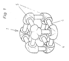
- a node 1 is shown in a perspective view, specifically in a position suitable for mutual engagement.
- node 1 It has the shape of a cube and has twelve round bars 4 as edges, which are connected to one another via rounded corner parts 5 in the present case.
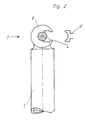
- the rod 2 to be fastened thereon has a connecting part 3 which is formed in the manner of a fork 6, the axis of which extends perpendicular to that of the rod 2.
- connection part 3 In order to enable the connection part 3 to be attached to the round rod 4, the inside width of the fork 6 must be chosen equal or (somewhat) larger than the outside diameter of the round rod 4 and the length of the connection part 3 measured perpendicular to the axis of the rod must be equal to or less than the distance between adjacent corner parts 5.
- the connecting part 3 is fixed on the end face of the rod 2 and partially engaging in it.
- a spring clip 8 is drawn, which is pushed onto the round rods 4 after the placement of the fork 6, that is, the state shown in the drawing, abuts the round rod 4 and engages in the two legs of the fork 6 for locking .
- the locking function takes place in the embodiment shown via the spring clip 8.
Landscapes
- Engineering & Computer Science (AREA)
- Architecture (AREA)
- Physics & Mathematics (AREA)
- Electromagnetism (AREA)
- Civil Engineering (AREA)
- Structural Engineering (AREA)
- Mutual Connection Of Rods And Tubes (AREA)
- Clamps And Clips (AREA)
- Supports For Plants (AREA)
- Joining Of Building Structures In Genera (AREA)
Description
- Die Erfindung betrifft ein Gitterwerk aus mehreren Stäben, die über Knoten miteinander verbunden sind und jeder Stab an seinem Ende ein dem Verbinden an dem Knoten dienendes Anschlußteil aufweist und der Knoten ein räumlicher Hohlkörper ist, der Rundstäbe aufweist, die über Eckteile miteinander verbunden sind, wobei das Anschlußteil den Rundstab eines Knotens umgreift und von den Eckteilen des Knotens seitlich flankiert ist.
- Gitterwerke der gattungsgemäßen Art sind aus der WO 87/03346 bekannt. An einem plattenförmigen Hohlkörper sind an der Stirnseite Rundstäbe angebracht, die von einem aus zwei Halbschalen gebildeten Anschlußteil umfaßt werden, die stirnseitig in den Stab eingeschoben sind. Die Fixierung erfolgt über einen auf dem Anschlußteil nach außen weisenden Nocken, welcher in eine im Stab befindliche Öffnung einrastet. Es handelt sich um ein Faltgestänge, das sich zur Herstellung dreidimensionaler Gitterwerke nur sehr bedingt eignet, da bei räumlich fixierten Knoten die Befestigung eines Stabes dazwischen nicht mehr möglich ist, da aufgrund des Erfordernisses des stirnseitigen Einschiebens des Anschlußteiles in den Stab eine Abstandsänderung zwischen beiden Knoten zwingend erforderlich ist. Zudem ist der Zusammenbau und das Auseinanderlegen umständlich und zeitraubend. Aus der FR-A 1 268 388 ist ein aus einer Vielzahl von Stäben aufgespanntes dreidimensionales Raumfachwerk bekannt, die unmittelbar miteinander über nach Art von Gabeln gebildeten Anschlußteilen verbunden sind, dergestalt, daß die Gabel auf den benachbarten Stab aufgeschoben wird. Die Möglichkeit der Variation der räumlichen Anordnung sind erheblich eingeschränkt durch die Tatsache, daß nur zwei Stäbe miteinander verbindbar sind und zum anderen durch den zwischen beiden durch das Anschlußstück fest vorgegebenen Winkel. Hinzu kommt, daß für bestimmte Anwendungsbereiche, wie z.B. Messebau, neben einer leichten Veränderung der Konstruktion des Gitterwerkes gleichzeitig ein rasches Verbinden und Zerlegen möglich sein soll. Aus der FR-A-2 331 745 ist allgemein die Verbindung von Stäben über Knoten, die Polyeder darstellen, bekannt, an deren Kanten die Stäbe über spitz zu laufende Anschlußteile befestigt sind. Eine Verwendung dieser Knotenkonstruktion bei Stäben, die als Anschlußteile Gabeln aufweisen, ist deshalb ungeeignet, da aufgrund des durch die Gabel bedingten Umgreifens der Kanten eine gegenseitige räumliche Behinderung der benachbarten Stäbe im Inneren des Polyeders bereits beim Einhaken entstehen würde.
- Hiervon ausgehend hat sich die Erfindung die Verbesserung derartiger Gitterwerke dahingehend zur Aufgabe gemacht, daß der Anschlußwinkel zwischen Stab und Knoten veränderbar ist sowie der Zusammenbau wesentlich rascher durchführbar ist. Gelöst wird diese Aufgabe durch die im Anspruch 1 angegebenen Merkmale.
- Das Aufbringen des als Gabel geformten Anschlußteiles auf den Knoten erfolgt über eine Bewegung des Stabes in radiale Richtung, wobei dessen Kante umgriffen wird. Die Festlegung erfolgt über eine Arretierung, die bewirkt, daß nach dem Aufschieben des Anschlußstückes auf den Knoten diese Lage beibehalten wird. Der als Würfel ausgebildete Knoten nimmt an seinen Kanten das Anschlußteil auf, die als Rundstab ausgebildet sein müssen, damit jeder denkbare Anschlußwinkel verwirklichbar ist. Die Kanten des Würfels sind deshalb Rundstäbe, die über Eckteile miteinander in Verbindung stehen. Die seitliche Flankierung der Gabel durch die Eckteile hat zur Folge, daß eine axiale Verschiebung unterbunden wird und eine zusätzliche Stabilität und seitliche Abstützung erreicht wird.
- Zur Arretierung wird eine Federklammer vorgeschlagen, die von außen her zwischen die beiden Schenkel der Gabel eingeschoben und dort festgelegt werden kann. Hierzu ist die Gabel innenseitig komplementär zur Federklammer geformt. Nach dem Einsetzen bewirkt die Federklammer eine Arretierung der von der Gabel aufzunehmenden stabförmigen Kante. Zur Montage wird die Gabel als erstes aufgesetzt und anschließend die Federklammer zwischen die Schenkel bis zur Anschlagposition eingeschoben und dort festgelegt. Zum Lösen der Verbindung wird in umgekehrter Reihenfolge die Federklammer entfernt und die Gabel abgezogen. Auch hier ist als Vorteil anzusehen, daß die Zug- und Druckbelastungen des Stabes vollständig über die Gabel übertragen werden und nicht durch die Federklammer selbst bestimmt und begrenzt werden. Die Belastbarkeit des Stabes bleibt voll erhalten.
- Der Vorteil durch Verwendung des erfindungsgemäßen Anschlußteiles besteht einmal darin, daß der Winkel zwischen Stab und Knoten grundsätzlich beliebig gewählt werden kann, so daß sich Gitterwerke mit unterschiedlichen und/oder veränderbaren Bauhöhen durch ein und denselben Knoten lediglich durch Veränderung des Anschlußwinkels realisieren lassen. Darüberhinaus lassen sich gekrümmte Konstruktionen mit allerdings unterschiedlich langen Stäben als Diagonalen aufbauen. Zusätzlich ist der Montageaufwand sehr gering, da kein Verschrauben oder langwieriges Festlegen am Knoten vorzunehmen ist. Die Befestigung erfolgt durch Aufpressen des Anschlußteiles bzw. des Stabes in radialer Richtung und das Lösen der Verbindung durch Aufbringen einer entsprechenden Kraft in entgegengesetzter Richtung. Die Gabel muß noch über die Federklammer geöffnet oder geschlossen werden.
- In einer zweckmäßigen Ausgestaltung wird vorgeschlagen, daß die die Kanten verbindenden Ecken in ihrem Außendurchmesser gleich dem des Anschlußteiles sind. Im eingesetzten Zustand ergeben sich aus Ecken und Anschlußteilen gebildete stufenlose Übergänge.
- In einer Weiterbildung ist vorgesehen, das Anschlußteil auf den Stab endseitig aufzusetzen und hierdurch zu befestigen.
- Weitere Einzelheiten, Merkmale und Vorteile der Erfindung lassen sich dem nachfolgendem Beschreibungsteil entnehmen, indem anhand der Zeichnung Ausführungsbeispiele der Erfindung näher erläutert werden.
- Es zeigen:
- Figur 1
- einen Knoten,
- Figur 2
- einen Stab mit Federklammer.
- In Figur 1 sind ein Knoten 1 in perspektivischer Darstellung widergegeben und zwar in für den gegenseitigen Eingriff geeigneter Position.
- Zunächst zum Knoten 1. Er hat die Form eines Würfels und weist als Kanten zwölf Rundstäbe 4 auf, die über im vorliegenden Fall nach außen zu gerundeten Eckteilen 5 miteinander verbunden sind.
- Der darauf zu befestigende Stab 2 weist ein Anschlußteil 3 auf, welches nach Art einer Gabel 6 gebildet ist, deren Achse senkrecht zu der des Stabes 2 verläuft.
- Um ein Aufbringen des Anschlußteiles 3 auf Rundstab 4 zu ermöglichen, muß einmal die lichte Weite der Gabel 6 gleich oder (etwas) größer als der Außendurchmesser des Rundstabes 4 gewählt werden und die senkrecht zur Achse des Stabs gemessene Länge des Anschlußteiles 3 gleich oder geringer als der Abstand benachbarter Eckteile 5. Das Anschlußteil 3 ist auf der Stirnseite des Stabes 2 und in diesen teilweise eingreifend festgelegt.
- In der Zeichnung ist lediglich ein einziger Stab 2 mit Anschlußteil 3 relativ zum Knoten 1 wiedergegeben. Doch stellt es den Regelfall dar, daß mehrere bis zu maximal zwölf Anschlußteile 3 und demzufolge auch die daran befestigten Stäbe 2 an ein und dem selben Knoten 1 befestigbar sind.
- In Figur 2 ist eine Federklammer 8 eingezeichnet ist, die nach dem Aufsetzen der Gabel 6 auf die Rundstäbe 4, also dem in der Zeichnung wiedergegebenen Zustand aufgeschoben wird, sich hierbei an den Rundstab 4 anlegt und in die beiden Schenkel der Gabel 6 zur Arretierung eingreift. Die Funktion des Arretierens erfolgt in der gezeigten Ausführungsform über die Federklammer 8.
- Im Ergebnis erhält man durch Verwendung der Stäbe 2 mit den Anschlußteilen 3 und/oder dem vorgeschlagenen Knoten 1 Gitterwerke von räumlichen Strukturen, die aufgrund des beliebig einstellbaren Anschlußwinkels zwischen Knoten 1 und Stab 2 beliebige Bauhöhen mit ein und demselben Knoten herstellen und realisieren lassen, wobei insbesondere im Falle der Verwendung der Anschlußteile 3 die Verbindung zwischen Stab 2 und Knoten 1 einfach herstellbar ist.
Claims (3)
- Gitterwerk aus mehreren Stäben, die über Knoten (1) miteinander verbunden sind und jeder Stab (2) an seinem Ende ein dem Verbinden an dem Knoten (1) dienendes Anschlußteil (2) aufweist und der Knoten (1) ein räumlicher Hohlkörper ist, der Rundstäbe (4) aufweist, die über Eckteile (5) miteinander verbunden sind, wobei das Anschlußteil (3) den Rundstab (4) eines Knotens (1) umgreift und von den Eckteilen (5) des Knotens (1) seitlich flankiert ist, dadurch gekennzeichnet, daß der Hohlkörper ein Würfel ist, dessen Kanten die Rundstäbe (4) biiden und das Anschlußteil (3) eine Gabel (6) ist, deren Achse senkrecht zum Stab (2) verläuft und als Arretierung endseitig über eine Federklammer (8) verschließbar ist.
- Gittwerwerk nach Anspruch 1, dadurch gekennzeichnet, daß der Außendurchmesser der die Kanten (4) verbindenden Eckteile (5) gleich dem des Anschlußteiles (3) ist.
- Gitterwerk nach einem der Ansprüche 1 bis 2, dadurch gekennzeichnet, daß das Anschlußteil (3) auf den Stab (2) gesetzt ist.
Priority Applications (1)
| Application Number | Priority Date | Filing Date | Title |
|---|---|---|---|
| AT88113196T ATE69848T1 (de) | 1987-09-17 | 1988-08-13 | Gitterwerk aus staeben und knoten. |
Applications Claiming Priority (2)
| Application Number | Priority Date | Filing Date | Title |
|---|---|---|---|
| DE19873731184 DE3731184A1 (de) | 1987-09-17 | 1987-09-17 | Gitterwerk aus staeben und knoten sowie dessen herstellung |
| DE3731184 | 1987-09-17 |
Publications (3)
| Publication Number | Publication Date |
|---|---|
| EP0307628A1 EP0307628A1 (de) | 1989-03-22 |
| EP0307628B1 EP0307628B1 (de) | 1991-11-27 |
| EP0307628B2 true EP0307628B2 (de) | 1997-08-27 |
Family
ID=6336185
Family Applications (1)
| Application Number | Title | Priority Date | Filing Date |
|---|---|---|---|
| EP88113196A Expired - Lifetime EP0307628B2 (de) | 1987-09-17 | 1988-08-13 | Gitterwerk aus Stäben und Knoten |
Country Status (4)
| Country | Link |
|---|---|
| US (1) | US5393163A (de) |
| EP (1) | EP0307628B2 (de) |
| AT (1) | ATE69848T1 (de) |
| DE (4) | DE3731184A1 (de) |
Families Citing this family (4)
| Publication number | Priority date | Publication date | Assignee | Title |
|---|---|---|---|---|
| FI102095B1 (fi) * | 1996-03-06 | 1998-10-15 | Rvt Messebau & Messedesign Gmb | Solmuliitinjärjestelmä |
| US7667731B2 (en) * | 2003-09-30 | 2010-02-23 | At&T Intellectual Property I, L.P. | Video recorder |
| US8172636B1 (en) | 2006-09-15 | 2012-05-08 | Pull-Buoy, Inc. | Playground hoop-holding apparatus |
| US7992353B2 (en) * | 2008-12-10 | 2011-08-09 | Athan Stephan P | Space frame hub joint |
Family Cites Families (24)
| Publication number | Priority date | Publication date | Assignee | Title |
|---|---|---|---|---|
| GB643507A (en) * | 1947-11-19 | 1950-09-20 | John Smith & Co London E Ltd | Improvements in or relating to structural elements comprising connected tubular members |
| DE1817913U (de) * | 1958-07-04 | 1960-09-08 | Wilhelm Layher Holzwarenfabrik | Bau- und arbeitsgeruest. |
| FR1268388A (fr) * | 1960-09-28 | 1961-07-28 | Thomas Ltd Martin | élément d'échafaudage |
| DE1860801U (de) * | 1962-04-21 | 1962-10-25 | Hermann Becker | Geruestsatz fuer fachwerkbau. |
| FR1418868A (fr) * | 1964-07-03 | 1965-11-26 | Vallourec | Dispositif d'assemblage de tubes ou organes analogues |
| US3550311A (en) * | 1967-09-20 | 1970-12-29 | John J Fouquart | Interengageable construction elements with resilient clutching parts |
| US3685221A (en) * | 1969-10-03 | 1972-08-22 | Joseph J Mangan | Expandable platform with building structures thereon |
| DE6941467U (de) * | 1969-10-21 | 1970-01-29 | Georges Dipl Ing Baghiriantz | Aus einzelnen bauteilen zusammengesetztes spielzeug |
| FR2171620A5 (de) * | 1972-02-09 | 1973-09-21 | Chamayou Gerard | |
| GB1520073A (en) * | 1975-03-13 | 1978-08-02 | Bauer H | Toy traffic signs |
| IT1033743B (it) * | 1975-08-12 | 1979-08-10 | Etal Ets | Giunto per il collegamento ad incastro di elementi a listello per la composizione modulare di strutture di giocattoli |
| FR2331745A1 (fr) * | 1975-11-14 | 1977-06-10 | Vuarnesson Bernard | Noeud d'assemblage polyedrique |
| NL7605017A (nl) * | 1976-05-11 | 1977-11-15 | Reobyn Bv | Speelgoedbouwsysteem. |
| US4129975A (en) * | 1977-03-09 | 1978-12-19 | Matrix Toys, Inc. | Construction set having clip fasteners |
| US4352255A (en) * | 1980-12-04 | 1982-10-05 | Warehime Norwood R | Group use toy structural construction set |
| US4480418A (en) * | 1981-07-14 | 1984-11-06 | Ettore Ventrella | Modular system for space grid structures |
| DE3301917A1 (de) * | 1983-01-21 | 1984-07-26 | Günther 5100 Aachen Kunz | Knotenpunkt fuer vektoraktive gebaeudetragwerke in schalenbauweise |
| GB8313507D0 (en) * | 1983-05-17 | 1983-06-22 | Green A W | Connector |
| US4565383A (en) * | 1984-02-03 | 1986-01-21 | Trek Bicycle Corporation | Front and rear wheel drop outs for bicycle frames |
| US4829735A (en) * | 1985-12-02 | 1989-05-16 | Entwurf Partner Ruedi Zwissler | Framework comprising bar-shaped elements |
| DE8608042U1 (de) * | 1986-03-22 | 1987-01-22 | Erich Schumm Gmbh, 7157 Murrhardt | Gitterknoten-Kupplung, insbesondere für folienbespannbare Gewächshaus-Rahmenkonstruktionen |
| DE8702043U1 (de) * | 1986-08-08 | 1987-04-23 | Vauth-Sagel GmbH & Co, 33034 Brakel | Verbindungsstück für winklig zusammenstoßende Gittermatten zur Bildung von Drahtgestellen |
| US4758196A (en) * | 1987-03-27 | 1988-07-19 | Wang Tsung Hsien | Block unit for making three-dimensional blocks composed of geometric points, lines and planes |
| IT1213606B (it) * | 1987-09-18 | 1989-12-29 | Quattrocchio Srl | Dispositivo di giunzione e collegamento particolarmente per strutture modulari a traliccio |
-
1987
- 1987-09-17 DE DE19873731184 patent/DE3731184A1/de not_active Ceased
- 1987-09-17 DE DE8717713U patent/DE8717713U1/de not_active Expired
-
1988
- 1988-08-13 DE DE8816979U patent/DE8816979U1/de not_active Expired - Lifetime
- 1988-08-13 DE DE8888113196T patent/DE3866487D1/de not_active Expired - Lifetime
- 1988-08-13 AT AT88113196T patent/ATE69848T1/de not_active IP Right Cessation
- 1988-08-13 EP EP88113196A patent/EP0307628B2/de not_active Expired - Lifetime
-
1991
- 1991-10-15 US US07/780,436 patent/US5393163A/en not_active Expired - Fee Related
Also Published As
| Publication number | Publication date |
|---|---|
| ATE69848T1 (de) | 1991-12-15 |
| EP0307628B1 (de) | 1991-11-27 |
| DE8816979U1 (de) | 1991-11-21 |
| DE8717713U1 (de) | 1989-10-12 |
| DE3731184A1 (de) | 1989-03-30 |
| US5393163A (en) | 1995-02-28 |
| EP0307628A1 (de) | 1989-03-22 |
| DE3866487D1 (de) | 1992-01-09 |
Similar Documents
| Publication | Publication Date | Title |
|---|---|---|
| DE3687293T2 (de) | Vollstaendig gegliederte lagerungsvorrichtung. | |
| DE2324697A1 (de) | Zerlegbarer gegenstand, insbesondere moebelstueck, und einzelbauteil zum aufbau des gegenstandes | |
| EP4064938A1 (de) | Windverband und möbelbausatz | |
| DE3224899A1 (de) | Verbindungselement fuer platten | |
| DE2632696B2 (de) | Montagesystem insbesondere für Dekorations- oder Möbelgestelle, Messe- und Ausstellungsstände, Rahmen, Pendeltürgriffe, Griffstangen, Handtuchhalter o.dgl | |
| DE3636639A1 (de) | Bauelement-system | |
| EP0875407A2 (de) | Lagerböckchen für eine Fahrzeug-Sonnenblende | |
| EP0773615B1 (de) | Schaltschrank für elektrische Anlagen | |
| EP0307628B2 (de) | Gitterwerk aus Stäben und Knoten | |
| DE2536922A1 (de) | Doppelgelenk zur verbindung von drei elementen eines faltbaren gestells | |
| DE1988325U (de) | Langgestrecktes moebelteil mit steckverbindung. | |
| EP1092881A2 (de) | Vorrichtung zum Befestigen oder Verbinden von Bauteilen | |
| EP1580341B1 (de) | Verbindugselement für eine Profilkonstruktion und Profilkonstruktion | |
| DE3001195A1 (de) | Schnappvorrichtung zur loesbaren verbindung von zwei teilen oder brettern | |
| DE69303216T2 (de) | Tischbeinanordnung | |
| DE202016102232U1 (de) | Verstellmechanismus mit der Möglichkeit zur schnellen Ent- und Verriegelung | |
| EP0772879A1 (de) | Mit hilfe von zapfen zusammengesetztes brennstabbündel | |
| DE69408756T2 (de) | Zusammensetzbarer Tisch | |
| EP0805281A1 (de) | Verbindungsanordnung mit zwei stabförmigen Profilen | |
| DE2612141A1 (de) | Verbindungs-beschlag | |
| DE102023005184A1 (de) | Kappe für eine Kappenanordnung | |
| DE8816856U1 (de) | Gitterwerk aus Stäben und Knoten sowie dessen Herstellung | |
| DE3206695A1 (de) | Gelenkverbindung zur loesbaren lagerung von wendetafeln in halteschienen | |
| DE3734533A1 (de) | Knotenpunktsystem fuer messestandkonstruktionen und aehnliche aufbauten aus hohlprofilstaeben | |
| CH694783A5 (de) | Zerlegbares Möbel |
Legal Events
| Date | Code | Title | Description |
|---|---|---|---|
| PUAI | Public reference made under article 153(3) epc to a published international application that has entered the european phase |
Free format text: ORIGINAL CODE: 0009012 |
|
| AK | Designated contracting states |
Kind code of ref document: A1 Designated state(s): AT CH DE FR GB IT LI SE |
|
| 17P | Request for examination filed |
Effective date: 19890701 |
|
| 17Q | First examination report despatched |
Effective date: 19900522 |
|
| GRAA | (expected) grant |
Free format text: ORIGINAL CODE: 0009210 |
|
| AK | Designated contracting states |
Kind code of ref document: B1 Designated state(s): AT CH DE FR GB IT LI SE |
|
| PG25 | Lapsed in a contracting state [announced via postgrant information from national office to epo] |
Ref country code: GB Free format text: LAPSE BECAUSE OF FAILURE TO SUBMIT A TRANSLATION OF THE DESCRIPTION OR TO PAY THE FEE WITHIN THE PRESCRIBED TIME-LIMIT Effective date: 19911127 Ref country code: FR Free format text: LAPSE BECAUSE OF FAILURE TO SUBMIT A TRANSLATION OF THE DESCRIPTION OR TO PAY THE FEE WITHIN THE PRESCRIBED TIME-LIMIT Effective date: 19911127 |
|
| REF | Corresponds to: |
Ref document number: 69848 Country of ref document: AT Date of ref document: 19911215 Kind code of ref document: T |
|
| REF | Corresponds to: |
Ref document number: 3866487 Country of ref document: DE Date of ref document: 19920109 |
|
| ITF | It: translation for a ep patent filed | ||
| GBT | Gb: translation of ep patent filed (gb section 77(6)(a)/1977) | ||
| ET | Fr: translation filed | ||
| PLBI | Opposition filed |
Free format text: ORIGINAL CODE: 0009260 |
|
| 26 | Opposition filed |
Opponent name: ZWISSLER, RUEDI Effective date: 19920724 |
|
| PLBI | Opposition filed |
Free format text: ORIGINAL CODE: 0009260 |
|
| 26 | Opposition filed |
Opponent name: ORIGON PRAESENTATIONSSYSTEME GMBH I.G. Effective date: 19931207 Opponent name: ZWISSLER, RUEDI Effective date: 19920724 |
|
| EAL | Se: european patent in force in sweden |
Ref document number: 88113196.5 |
|
| PGFP | Annual fee paid to national office [announced via postgrant information from national office to epo] |
Ref country code: FR Payment date: 19960916 Year of fee payment: 9 |
|
| PGFP | Annual fee paid to national office [announced via postgrant information from national office to epo] |
Ref country code: SE Payment date: 19960919 Year of fee payment: 9 |
|
| PGFP | Annual fee paid to national office [announced via postgrant information from national office to epo] |
Ref country code: CH Payment date: 19960923 Year of fee payment: 9 |
|
| PGFP | Annual fee paid to national office [announced via postgrant information from national office to epo] |
Ref country code: GB Payment date: 19960930 Year of fee payment: 9 |
|
| PLAW | Interlocutory decision in opposition |
Free format text: ORIGINAL CODE: EPIDOS IDOP |
|
| APAC | Appeal dossier modified |
Free format text: ORIGINAL CODE: EPIDOS NOAPO |
|
| APAC | Appeal dossier modified |
Free format text: ORIGINAL CODE: EPIDOS NOAPO |
|
| PUAH | Patent maintained in amended form |
Free format text: ORIGINAL CODE: 0009272 |
|
| STAA | Information on the status of an ep patent application or granted ep patent |
Free format text: STATUS: PATENT MAINTAINED AS AMENDED |
|
| PG25 | Lapsed in a contracting state [announced via postgrant information from national office to epo] |
Ref country code: SE Free format text: LAPSE BECAUSE OF NON-PAYMENT OF DUE FEES Effective date: 19970814 |
|
| 27A | Patent maintained in amended form |
Effective date: 19970827 |
|
| AK | Designated contracting states |
Kind code of ref document: B2 Designated state(s): AT CH DE FR GB IT LI SE |
|
| PG25 | Lapsed in a contracting state [announced via postgrant information from national office to epo] |
Ref country code: LI Free format text: LAPSE BECAUSE OF NON-PAYMENT OF DUE FEES Effective date: 19970831 Ref country code: CH Free format text: LAPSE BECAUSE OF NON-PAYMENT OF DUE FEES Effective date: 19970831 |
|
| REG | Reference to a national code |
Ref country code: CH Ref legal event code: AEN Free format text: AUFRECHTERHALTUNG DES PATENTES IN GEAENDERTER FORM |
|
| EN | Fr: translation not filed | ||
| GBV | Gb: ep patent (uk) treated as always having been void in accordance with gb section 77(7)/1977 [no translation filed] |
Effective date: 19911127 |
|
| REG | Reference to a national code |
Ref country code: CH Ref legal event code: PL |
|
| PGFP | Annual fee paid to national office [announced via postgrant information from national office to epo] |
Ref country code: AT Payment date: 20010824 Year of fee payment: 14 |
|
| PG25 | Lapsed in a contracting state [announced via postgrant information from national office to epo] |
Ref country code: AT Free format text: LAPSE BECAUSE OF NON-PAYMENT OF DUE FEES Effective date: 20020813 |
|
| PGFP | Annual fee paid to national office [announced via postgrant information from national office to epo] |
Ref country code: DE Payment date: 20021017 Year of fee payment: 15 |
|
| PG25 | Lapsed in a contracting state [announced via postgrant information from national office to epo] |
Ref country code: DE Free format text: LAPSE BECAUSE OF NON-PAYMENT OF DUE FEES Effective date: 20040302 |
|
| PG25 | Lapsed in a contracting state [announced via postgrant information from national office to epo] |
Ref country code: IT Free format text: LAPSE BECAUSE OF NON-PAYMENT OF DUE FEES Effective date: 20050813 |
|
| APAH | Appeal reference modified |
Free format text: ORIGINAL CODE: EPIDOSCREFNO |