EP0307618A1 - Vorrichtung zum Beschichten einer um eine Gegenwalze geführten Materialbahn - Google Patents
Vorrichtung zum Beschichten einer um eine Gegenwalze geführten Materialbahn Download PDFInfo
- Publication number
- EP0307618A1 EP0307618A1 EP88112976A EP88112976A EP0307618A1 EP 0307618 A1 EP0307618 A1 EP 0307618A1 EP 88112976 A EP88112976 A EP 88112976A EP 88112976 A EP88112976 A EP 88112976A EP 0307618 A1 EP0307618 A1 EP 0307618A1
- Authority
- EP
- European Patent Office
- Prior art keywords
- elastic
- knife
- pressure
- scraper knife
- independently
- Prior art date
- Legal status (The legal status is an assumption and is not a legal conclusion. Google has not performed a legal analysis and makes no representation as to the accuracy of the status listed.)
- Granted
Links
- 238000000576 coating method Methods 0.000 title claims abstract description 27
- 239000011248 coating agent Substances 0.000 title claims abstract description 22
- 239000000463 material Substances 0.000 title claims abstract description 7
- 238000007790 scraping Methods 0.000 abstract 5
- 239000011111 cardboard Substances 0.000 description 2
- 238000006073 displacement reaction Methods 0.000 description 2
- 230000000694 effects Effects 0.000 description 2
- 239000011087 paperboard Substances 0.000 description 2
- 230000001105 regulatory effect Effects 0.000 description 2
- 230000006835 compression Effects 0.000 description 1
- 238000007906 compression Methods 0.000 description 1
- 230000001276 controlling effect Effects 0.000 description 1
- 238000010586 diagram Methods 0.000 description 1
- 239000010985 leather Substances 0.000 description 1
- 239000007788 liquid Substances 0.000 description 1
- 238000004519 manufacturing process Methods 0.000 description 1
- 239000003973 paint Substances 0.000 description 1
- 238000010422 painting Methods 0.000 description 1
- 239000000123 paper Substances 0.000 description 1
- 230000010076 replication Effects 0.000 description 1
- 230000000284 resting effect Effects 0.000 description 1
Images


Classifications
-
- B—PERFORMING OPERATIONS; TRANSPORTING
- B05—SPRAYING OR ATOMISING IN GENERAL; APPLYING FLUENT MATERIALS TO SURFACES, IN GENERAL
- B05C—APPARATUS FOR APPLYING FLUENT MATERIALS TO SURFACES, IN GENERAL
- B05C11/00—Component parts, details or accessories not specifically provided for in groups B05C1/00 - B05C9/00
- B05C11/02—Apparatus for spreading or distributing liquids or other fluent materials already applied to a surface ; Controlling means therefor; Control of the thickness of a coating by spreading or distributing liquids or other fluent materials already applied to the coated surface
- B05C11/04—Apparatus for spreading or distributing liquids or other fluent materials already applied to a surface ; Controlling means therefor; Control of the thickness of a coating by spreading or distributing liquids or other fluent materials already applied to the coated surface with blades
- B05C11/041—Apparatus for spreading or distributing liquids or other fluent materials already applied to a surface ; Controlling means therefor; Control of the thickness of a coating by spreading or distributing liquids or other fluent materials already applied to the coated surface with blades characterised by means for positioning, loading, or deforming the blades
- B05C11/042—Apparatus for spreading or distributing liquids or other fluent materials already applied to a surface ; Controlling means therefor; Control of the thickness of a coating by spreading or distributing liquids or other fluent materials already applied to the coated surface with blades characterised by means for positioning, loading, or deforming the blades allowing local positioning, loading or deforming along the blades
-
- D—TEXTILES; PAPER
- D21—PAPER-MAKING; PRODUCTION OF CELLULOSE
- D21H—PULP COMPOSITIONS; PREPARATION THEREOF NOT COVERED BY SUBCLASSES D21C OR D21D; IMPREGNATING OR COATING OF PAPER; TREATMENT OF FINISHED PAPER NOT COVERED BY CLASS B31 OR SUBCLASS D21G; PAPER NOT OTHERWISE PROVIDED FOR
- D21H25/00—After-treatment of paper not provided for in groups D21H17/00 - D21H23/00
- D21H25/08—Rearranging applied substances, e.g. metering, smoothing; Removing excess material
- D21H25/10—Rearranging applied substances, e.g. metering, smoothing; Removing excess material with blades
Definitions
- the invention relates to a device for coating a web of material guided around a counter roller with an elastic doctor blade, the base of which is clamped in a clamping bar and which is supported below its tip by a support bar, and with adjusting elements for influencing the contact pressure, which are arranged across the knife width individual areas of the doctor knife act independently of each other. Coating devices of this type are used in particular for coating paper and cardboard.
- the doctor blade arranged after the application unit doses the coating color to the desired coat weight.
- the line quality is decisively influenced by the geometry of the doctor knife in its area adjacent to the counter roller.
- the coating weight is adjusted via the contact pressure of the doctor knife against the counter roller, which is determined by the pretension of the doctor knife. In order to avoid line quality losses, it is necessary when the contact pressure is varied that the geometry of the doctor knife tip is kept essentially constant.
- the flexible support bar can be adjusted via tension and compression screws along the support line, depending on whether the coat weight is too high or too low at the corresponding points.
- This known coating device has two major disadvantages: - A local correction of the line weight over the working width via the contact pressure is not possible without simultaneously changing the geometry of the doctor knife tip. The result of this is that quality changes can temporarily occur locally and that the desired effect takes effect only after a delay. - Automatic control of the local distribution of the contact pressure during painting is not possible.
- the object of the invention is to remedy these disadvantages.
- the cross-section correction is carried out by adjusting the scraper knife foot in the clamping bar and thus at a maximum distance from the support bar. Therefore, in these embodiments, the geometry of the doctor blade tip is not changed during the cross-section correction.
- the sub-claims 9 to 11 contain advantageous embodiments of a device according to claim 8, which enable an automatically controlled cross profile correction.
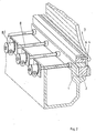
- FIGS. 1 and 2 contains a metering system, consisting of a pivotable scraper bar 1, in which a clamping bar 2, which is flexible transversely to the web within limits, is slidably mounted in the direction of the counter-roller 3.
- a scraper knife 4 is releasably clamped on its base in the clamping bar 2.
- a support bar 6 engages on the Scraper knife 4, which is also slidably attached to the scraper bar 1 approximately parallel to the clamping bar 2.
- the support bar 6, which extends over the working width, is slotted at regular intervals on the side opposite the support line and is therefore flexible within limits. Adjusting screws 7 arranged on this side engage at regular intervals, which enable manual adjustment of a locally different contact pressure across the width of the scraper knife 4.
- the flexible clamping bar 2 can be adjusted locally differently in the direction of the counter roller 3 by means of screw jacks 8, which are arranged at regular intervals (approx. 50-100 mm) over the working width.
- the screw jacks 8 each have a drive 8.1, which is controlled by a control device, not shown, with a measuring device for determining the cross profile of the coating weight.
- the drives 8.1 of the screw jacks 8 can be coupled so that they can be adjusted together to set the pretension at the beginning of the coating process.
- pneumatically or hydraulically operated adjustment elements or thermal expansion elements, for. B. expansion rods can be used.
- the cross-profile correction device is integrated in the clamping bar, which can be adjusted approximately horizontally in a range of approximately 20 mm.
- the base of the scraper knife 4 is clamped between the approximately vertical leg 9 of an angle bar and a back pressure hose 10 fastened in the clamping bar 2.
- the approximately horizontal leg 11 of the angle bar - it is located below the counterpressure hose 10 - is provided with regular slits at the end over the working width and ends when the scraper knife 4 is clamped in at a certain distance from the clamping bar 2. This allows limits (approx. 3 - 4 mm) an approximately horizontal displacement of the scraper knife base relative to the clamping bar 2.
- the displacement is effected with bellows 12 arranged side by side over the working width in the clamping bar 2, which lie against the vertical leg 9 of the angle bar on the side facing away from the scraper knife 4.
- Each bellows 12 has its own supply line 13 for air or liquid, so that the pressure in each bellows 12 can be regulated individually.
- the back pressure hose 10, which extends over the working width, has a compressed air supply with which a preselected, constant back pressure can be set.
- the associated control device for controlling the pressure distribution in the bellows 12 as a function of the transverse profile of the coating weight is not shown in FIG. 3.
- FIG. 4 The operation of the device according to FIG. 3 is illustrated in FIG. 4.
- the geometry and the contact pressure of the doctor knife tip are set to the desired target coating weight (line a).
- the pretension of the scraper knife 4, which is decisive for the contact pressure, is set in the scraper bar 1 by moving the support bar 6 and the clamping bar 2 relative to one another.
- a uniform cross profile of the coat weight is achieved.
- a measuring device continuously measures the line weights in the individual transverse areas of the paper web.
- the permissible range of the coat weight is limited in FIG. 4 by lines b and c.
- the control device increases the pressure in the bellows 12, which act on the doctor blade 4 in these areas.
- the clamped part of the scraper knife 4 is elastically deformed in these areas in the direction of the counter pressure hose 10.
- the area diagram d shows the necessary pressure distribution in the individual bellows 12 in order to compensate for the impermissibly high coat weight in the area b. Accordingly, the pressure in individual bellows 12 is reduced if the coat weight in the associated areas is too low.
- the cross-profile correction is carried out analogously.
- the screw jacks 8 which were coupled for prestressing, are decoupled from one another and adjusted individually in a controlled manner.
- the areas of the clamping bar 2 in which an excessively high coat weight is dosed are adjusted away from the counter-roller 3 by means of the screw jacks 8. Since the scraper knife foot is immovably clamped in the flexible clamping beam 2, it is also adjusted so that the coating weight is reduced in the corresponding area.
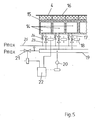
- the adjustment of the individual areas of the doctor blade 4 is effected with a plurality of pressure chambers 14 arranged side by side over the working width.
- the wall 15 leather pressure chamber 14 facing the scraper knife 4 is elastic.
- the elastic walls 15 are connected to an elastic compensation strip 16 which bears against the doctor blade 4.
- Each pressure chamber 14 has its own compressed air supply line 17 with a control valve 18, which are connected to a common supply line 19.
- the pressure in the supply line 19 is regulated by a computer 22 with the aid of a pressure measuring device 20 and a control valve 21.
- the computer 22 also regulates the pressure in each individual pressure chamber 18.
- This cross-profile correction device is particularly suitable for replication in existing coating devices, since it can be used instead of the manually profiled support bar. It is not necessary to constructively change the clamping bar 2.
- a pressure is built up in the supply line 19, which ensures the desired contact pressure of the doctor knife tip.
- the control valves 18 an average pressure is set in each pressure chamber 14.
- the computer 22 opens or closes the individual control valves 18 depending on the measured profile of the coating weight distribution. At the same time, he controls the pressure in the supply line 19 depending on the need in the individual pressure chambers 14.
- the correction of the pressure values in the individual chambers 14 is carried out at regular time intervals.
- the current value of the pressure in a chamber 14 is stored in computer 22 each time a control valve 18 is closed. This value serves as the basis for the next correction
Abstract
Description
- Die Erfindung betrifft eine Vorrichtung zum Beschichten einer um eine Gegenwalze geführten Materialbahn mit einem elastischen Schabermesser, dessen Fuß in einem Klemmbalken eingespannt ist und das unterhalb seiner Spitze von einer Abstützleiste abgestützt wird, und mit Verstellelementen zum Beeinflussen des Anpreßdrucks, die über die Messerbreite angeordnet auf einzelne Bereiche des Schabermessers unabhängig voneinander einwirken. Derartige Beschichtungsvorrichtungen dienen insbesondere zum Streichen von Papier und Karton.
- Sie weisen ein Auftragwerk (Walzen- oder Düsenauftragwerk) auf, mit denen die Streichfarbe im Überschuß auf die Bahn aufgebracht wird. Das im Anschluß an das Auftragwerk angeordnete Schabermesser dosiert die Streichfarbe auf das gewünschte Strichgewicht. Die Strichqualität wird entscheidend von der Geometrie des Schabermessers in seinem an der Gegenwalze anliegenden Bereich beeinflußt. Die Einstellung des Strichgewichts erfolgt über den Anpreßdruck des Schabermessers an die Gegenwalze, der von der Vorspannung des Schabermessers bestimmt wird. Um Strichqualitätseinbußen zu vermeiden, ist es bei einer Variation des Anpreßdrucks erforderlich, daß die Geometrie der Schabermesserspitze im wesentlichen konstant gehalten wird.
- Beim Streichen von Papier- oder Kartonbahnen treten produktionsbedingte Schwankungen im Querprofil der Bahnen auf, die es erforderlich machen, den Anpreßdruck des Schabermessers über die Arbeitsbreite lokal unterschiedlich einzustellen, um einen gleichmäßigen Strich zu erhalten. Dazu kann in der gattungsgemäßen Vorrichtung nach der DE-PS 28 25 907 die in Grenzen biegsame Abstützleiste über Zug- und Druckschrauben entlang der Unterstützungslinie einjustiert werden, je nach dem, ob das Strichgewicht an den entsprechenden Stellen zu hoch oder zu niedrig ist.
- Diese bekannte Streichvorrichtung weist zwei gewichtige Nachteile auf:
- Eine lokale Korrektur des Strichgewichts über die Arbeitsbreite über den Anpreßdruck ist nicht möglich, ohne daß gleichzeitig die Geometrie der Schabermesserspitze verändert wird. Dies hat zur Folge, daß lokal vorübergehend Qualitätsveränderungen auftreten können und daß der gewünschte Effekt erst zeitverzögert zur Wirkung kommt.
- Eine automatische Regelung der lokalen Verteilung des Anpreßdrucks während des Streichens ist nicht möglich. - Der Erfindung liegt die Aufgabe zugrunde, diese Nachteile zu beheben.
- Diese Aufgabe wird durch die Merkmale der Ansprüche 1 und 8 gelöst.
- Mit den Merkmalen der Ansprüche 1 und 8 wird eine geregelte Querprofilkorrektur während des Streichens unabhängig von der vor Beginn des Streichens eingestellten Vorspannung ermöglicht. Die Vorrichtung nach Anspruch 1 hat den weiteren Vorteil, daß die die Vorspannung bestimmende Abstützlinie unverändert gelassen wird und somit bei der Querprofilkorrektur die Geometrie der Schabermesserspitze kaum verändert wird.
- Die Unteransprüche enthalten bevorzugte Ausführungsformen der Erfindung.
- Bei den Vorrichtungen nach den Unteransprüchen 2 bis 7 erfolgt die Querprofilkorrektur durch Verstellen des Schabermesserfußes in Klemmbalken und somit in einem maximalen Abstand zur Abstützleiste. Daher wird bei diesen Ausführungsformen die Geometrie der Schabermesserspitze bei der Querprofilkorrektur nicht verändert.
- Die Unteransprüche 9 bis 11 enthalten vorteilhafte Ausführungsformen einer Vorrichtung nach Anspruch 8, die eine automatisch geregelte Querprofilkorrektur ermöglichen.
- Die Zeichnungen dienen zur Erläuterung der Erfindung anhand vereinfacht dargestellter Ausführungsbeispiele.
- Fig. 1 zeigt einen Schnitt in Bahnlaufrichtung durch eine Vorrichtung mit einem biegsamen, lokal verstellbaren Klemmbalken.
- Fig. 2 zeigt eine Perspekive quer zur Bahn von Fig. 1.
- Fig. 3 zeigt einen Schnitt durch eine Beschichtungsvorrichtung mit einer in den Klemmbalken integrierten Querprofilkorrektureinrichtung.
- Fig.4 zeigt schematisch die Korrektur des Strichgewichtquerprofils bei einer Vorrichtung nach Fig. 3.
- Fig. 5 zeigt schematisch den Aufbau einer Vorrichtung mit Druckkammern als Verstellelemente.
- Die in den Fig. 1 und 2 gezeigte Ausführungsform enthält ein Dosiersystem, bestehend aus einem schwenkbaren Schaberbalken 1, in dem ein quer zur Bahn in Grenzen biegsamer Klemmbalken 2 in Richtung zur Gegenwalze 3 verschiebbar gelagert ist. Im Klemmbalken 2 ist ein Schabermesser 4 an seinem Fuß lösbar eingespannt.
- Unterhalb der an der Gegenwalze 3 anliegenden Schabermesserspitze 5 greift eine Abstützleiste 6 an dem Schabermesser 4 an, die ebenfalls am Schaberbalken 1 in etwa parallel zum Klemmbalken 2 verschiebbar befestigt ist. Die sich über die Arbeitsbreite erstreckende Abstützleiste 6 ist an der der Abstützlinie entgegengesetzten Seite in regelmäßigen Abständen geschlitzt und daher in Grenzen biegsam. An dieser Seite greifen in regelmäßigen Abständen angeordnete Stellschrauben 7 an, die eine manuelle Einstellung eines lokal unterschiedlichen Anpreßdrucks über die Breite des Schabermessers 4 ermöglichen.
- Der biegsame Klemmbalken 2 ist mittels Spindelhubwerken 8, die in regelmäßigen Abständen (ca. 50 - 100 mm) über die Arbeitsbreite angeordnet sind, lokal unterschiedlich in Richtung der Gegenwalze 3 verstellbar. Dazu weisen die Spindelhubwerke 8 jeweils einen Antrieb 8.1 auf, der von einer nicht dargestellten Regelvorrichtung mit einem Meßgerät zur Bestimmung des Querprofils des Strichgewichts geregelt wird. Zusätzlich sind die Antriebe 8.1 der Spindelhubwerke 8 koppelbar, damit diese zur Einstellung der Vorspannung zu Beginn des Streichvorgangs gemeinsam verstellt werden können. Anstelle der Spindelhubwerke 8 können auch pneumatisch oder hydraulisch betätigte Verstellelemente oder thermische Ausdehnungselemente, z. B. Dehnstäbe, eingesetzt werden.
- Bei der Ausführungsform nach Fig. 3 ist die Querprofilkorrektureinrichtung in den in etwa horizontal in einem Bereich von ca. 20 mm verstellbaren Klemmbalken integriert. Dazu ist der Fuß des Schabermessers 4 zwischen dem in etwa senkrechten Schenkel 9 einer Winkelleiste und einem im Klemmbalken 2 befestigten Gegendruckschlauch 10 eingespannt. Der in etwa waagerechte Schenkel 11 der Winkelleiste - er befindet sich unterhalb des Gegendruckschlauchs 10 - ist an seinem Ende über die Arbeitsbreite mit regelmäßigen Schlitzen versehen und endet bei eingespanntem Schabermesser 4 in einem gewissen Abstand vom Klemmbalken 2. Dies ermöglicht in Grenzen (ca. 3 - 4 mm) eine in etwa waagerechte Verschiebung des Schabermesserfußes relativ zum Klemmbalken 2. Die Verschiebung wird mit nebeneinander über die Arbeitsbreite im Klemmbalken 2 angeordneten Bälgen 12 bewirkt, die an dem senkrechten Schenkel 9 der Winkelleiste an der dem Schabermesser 4 abgewandten Seite anliegen. Jeder Balg 12 weist eine eigene Zufuhrleitung 13 für Luft- oder Flüssigkeit auf, so daß der Druck in jedem Balg 12 individuell geregelt werden kann. Der sich über die Arbeitsbreite erstreckende Gegendruckschlauch 10 weist eine Druckluftzufuhr auf, mit der ein vorgewählter, konstanter Gegendruck eingestellt werden kann. Die zugehörige Regeleinrichtung zur Regelung der Druckverteilung in den Bälgen 12 in Abhängigkeit vom Querprofil des Strichgewichts ist in Fig. 3 nicht dargestellt.
- In Fig. 4 wird die Funktionsweise der Vorrichtung nach Figur 3 verdeutlicht. Bei Beginn des Streichvorgangs wird die Geometrie und der Anpreßdruck der Schabermesserspitze auf das gewünschte Soll-Strichgewicht eingestellt (Linie a). Die für den Anpreßdruck entscheidende Vorspannung des Schabermessers 4 wird durch Verschieben der Abstützleiste 6 und des Klemmbalkens 2 relativ zueinander im Schaberbalken 1 eingestellt. Durch Justierung der Stellschrauben 7 an der Abstützleiste 6 wird ein gleichmäßiges Querprofil des Strichgewichts erreicht. Während des Streichvorgangs mißt ein Meßgerät permanent die Strichgewichte im einzelnen Querbereichen der Papierbahn. Der zulässige Bereich des Strichgewichts wird in Fig. 4 von den Linien b und c begrenzt. Wird das Strichgewicht in einem oder mehreren Bereichen unzulässig hoch (Bereich d), erhöht die Regeleinrichtung den Druck in den Bälgen 12, die in diesen Bereichen auf das Schabermesser 4 einwirken. Durch diese Druckerhöhung wird der eingespannte Teil des Schabermessers 4 in diesen Bereichen in Richtung zum Gegendruckschlauch 10 elastisch verformt. Dies führt in den entsprechenden Bereichen zu einem Absinken des Anpreßdrucks an der Schabermesserspitze 5 und damit zu einem Absinken des Strichgewichts bis das Soll-Strichgewicht wieder erreicht ist. Das Flächendiagramm d zeigt die notwendige Druckverteilung in den einzelnen Bälgen 12, um das unzulässig hohe Strichgewicht im Bereich b zu kompensieren. Entsprechend wird der Druck in einzelnen Bälgen 12 abgesenkt, falls das Strichgewicht in den zugehörigen Bereichen zu niedrig ist.
- Bei der Ausführungsform nach Fig. 1 und 2 erfolgt die Querprofilkorrektur analog. Nach Beginn des Strichvorgangs werden die Spindelhubwerke 8, die zur Vorspannungseinstellung gekoppelt waren, voneinander entkoppelt und einzeln geregelt verstellt.
- Dabei werden die Bereiche des Klemmbalkens 2, in denen ein zu hohes Strichgewicht dosiert wird, mittels der Spindelhubwerke 8 von der Gegenwalze 3 wegverstellt. Da der Schabermesserfuß unbeweglich in dem biegsamen Klemmbalken 2 eingespannt ist, wird er mitverstellt, so daß das Strichgewicht in dem entsprechenden Bereich verringert wird.
- Bei der Querprofilkorrektureinrichtung nach Fig. 5 wird die Verstellung der einzelnen Bereiche des Schabermessers 4 mit mehreren, nebeneinander über die Arbeitsbreite angeordneten Druckkammern 14 bewirkt. Die dem Schabermesser 4 zugewandte Wand 15 leder Druckkammer 14 ist elastisch. Die elastischen Wände 15 sind mit einer elastischen Ausgleichsleiste 16 verbunden, die an dem Schabermesser 4 anliegt.
- Jede Druckkammer 14 hat eine eigene Druckluftzufuhrleitung 17 mit einem Stellventil 18, die an einer gemeinsamen Versorgungsleitung 19 angeschlossen sind. Der Druck in der Versorgungsleitung 19 wird mit Hilfe eines Druckmeßgerätes 20 und eines Stellventils 21 von einem Rechner 22 geregelt. Der Rechner 22 regelt ebenfalls den Druck in jeder einzelnen Druckkammer 18.
- Zusätzliche Druckluftzufuhrleitungen 23, jeweils mit einem manuell betätigbaren Ventil 24, die an einer gemeinsamen Versorgungsleitung 25 angeschlossen sind, ermöglichen eine manuelle Einstellung des Drucks in jeder Kammer 14.
- Diese Querprofilkorrektureinrichtung ist besonders zum Nachbau in bestehende Beschichtungsvorrichtungen geeignet, da sie anstelle der manuell profilierbaren Abstützleiste eingesetzt werden kann. Es ist nicht erforderlich, den Klemmbalken 2 konstruktiv zu verändern.
- Bei Beginn des Streichvorgangs wird in der Versorgungsleitung 19 ein Druck aufgebaut, der den gewünschten Anpreßdruck der Schabermesserspitze gewährleistet. Mit den Stellventilen 18 wird ein mittlerer Druck in jeder Druckkammer 14 eingestellt. Nachdem mit Streichen begonnen wurde, öffnet oder schließt der Rechner 22 die einzelnen Stellventile 18 in Abhängigkeit von dem gemessenen Profil der Strichgewichtsverteilung. Gleichzeitig steuert er den Druck in der Versorgungsleitung 19 in Abhängigkeit vom Bedarf in den einzelnen Druckkammern 14.
- Die Korrektur der Druckwerte in den einzelnen Kammern 14 wird in regelmäßigen Zeitabständen durchgeführt. Dazu wird bei jedem Schließen eines Stellventils 18 der aktuelle Wert des Drucks in einer Kammer 14 in Rechner 22 abgespeichert. Dieser Wert dient als Grundlage für die nächste Korrektur
Claims (11)
- mit einem elastischen Schabermesser (4), dessen Fuß in einem Klemmbalken (2) eingespannt ist und das unterhalb seiner Spitze (5) von einer Abstützleiste (6) abgestützt wird,
- und mit Verstellelementen zur Beeinflussung des Anpreßdrucks, die über die Messerbreite angeordnet auf einzelne Bereiche des Schabermessers (4) unabhängig voneinander einwirken,
dadurch gekennzeichnet, daß die Verstellelemente (8, 9-12) unterhalb der Abstützleiste (6) auf das Schabermesser (4) einwirken.
- mit einem elastischen Schabermesser (4), dessen Fuß in einem Klemmbalken (2) eingespannt ist und das unterhalb seiner Spitze (5) von einer Abstützleiste (6) abgestützt wird,
- und mit Verstellelementen zur Beeinflussung des Anpreßdrucks, die über die Messerbreite angeordnet auf einzelne Bereiche des Schabermessers (4) unabhängig voneinander einwirken,
dadurch gekennzeichnet, daß die Verstellelemente aus mehreren, über die Arbeitsbreite nebeneinander angeordneten, unabhängig mit Druck beaufschlagbaren Druckkammern (14) bestehen, die jeweils eine dem Schabermesser (4) zugewandte elastische Wand (15) aufweisen.
Priority Applications (1)
| Application Number | Priority Date | Filing Date | Title |
|---|---|---|---|
| AT88112976T ATE69980T1 (de) | 1987-09-04 | 1988-08-10 | Vorrichtung zum beschichten einer um eine gegenwalze gefuehrten materialbahn. |
Applications Claiming Priority (2)
| Application Number | Priority Date | Filing Date | Title |
|---|---|---|---|
| DE19873729621 DE3729621A1 (de) | 1987-09-04 | 1987-09-04 | Vorrichtung zum beschichten einer um eine gegenwalze gefuehrten materialbahn |
| DE3729621 | 1987-09-04 |
Publications (2)
| Publication Number | Publication Date |
|---|---|
| EP0307618A1 true EP0307618A1 (de) | 1989-03-22 |
| EP0307618B1 EP0307618B1 (de) | 1991-12-04 |
Family
ID=6335236
Family Applications (1)
| Application Number | Title | Priority Date | Filing Date |
|---|---|---|---|
| EP88112976A Expired - Lifetime EP0307618B1 (de) | 1987-09-04 | 1988-08-10 | Vorrichtung zum Beschichten einer um eine Gegenwalze geführten Materialbahn |
Country Status (7)
| Country | Link |
|---|---|
| US (1) | US4899687A (de) |
| EP (1) | EP0307618B1 (de) |
| JP (1) | JPS6490062A (de) |
| AT (1) | ATE69980T1 (de) |
| BR (1) | BR8804540A (de) |
| DE (2) | DE3729621A1 (de) |
| FI (1) | FI884050A (de) |
Cited By (5)
| Publication number | Priority date | Publication date | Assignee | Title |
|---|---|---|---|---|
| FR2639372A1 (fr) * | 1988-11-18 | 1990-05-25 | Valmet Paper Machinery Inc | Procede de compensation de la flexion d'une racle et racle a flexion compensee |
| EP0418476A2 (de) * | 1989-08-18 | 1991-03-27 | JAGENBERG Aktiengesellschaft | Vorrichtung zum Beschichten einer um eine Gegenwalze geführten Materialbahn |
| WO1993017795A1 (de) * | 1992-03-11 | 1993-09-16 | Jagenberg Aktiengesellschaft | Abstützleiste für eine beschichtungsvorrichtung |
| WO1995016074A1 (de) * | 1993-12-06 | 1995-06-15 | Jagenberg Papiertechnik Gmbh | Dosiersystem für vorrichtung zum beschichten von materialbahnen, insbesondere papier- oder kartonbahnen |
| US5733373A (en) * | 1992-03-11 | 1998-03-31 | Jagenberg Aktiengesellschaft | Pressure strip for coating device |
Families Citing this family (23)
| Publication number | Priority date | Publication date | Assignee | Title |
|---|---|---|---|---|
| DE3908386A1 (de) * | 1989-03-15 | 1990-09-27 | Jagenberg Ag | Verfahren und vorrichtung zum beschichten von materialbahnen, insbesondere von papier- oder kartonbahnen |
| DE3934986A1 (de) * | 1989-10-20 | 1991-04-25 | Jagenberg Ag | Vorrichtung zum beschichten einer um eine gegenwalze gefuehrten materialbahn |
| US5147462A (en) * | 1990-02-16 | 1992-09-15 | Alcan Aluminum Corporation | Apparatus for automatic film thickness control |
| FI91025C (fi) * | 1991-02-08 | 1995-08-22 | Valmet Paper Machinery Inc | Menetelmä paperin tai muun rainamateriaalin päällystemäärän poikkiprofiilin säätämiseksi ja menetelmän toteuttamiseen tarkoitettu päällystysasema |
| FI100313B (fi) * | 1991-05-09 | 1997-11-14 | Valmet Corp | Menetelmä ja laite liikkuvan alustan päällystämiseksi |
| DE9109787U1 (de) * | 1991-08-07 | 1991-09-26 | J.M. Voith Gmbh, 7920 Heidenheim, De | |
| SE9102783L (sv) * | 1991-09-25 | 1992-12-21 | Btg Kaelle Inventing Ab | Anordning och foerfarande foer bladbestrykning av en loepande bana |
| DE69307133T2 (de) * | 1992-03-31 | 1997-04-24 | Minnesota Mining & Mfg | Riegelvorrichtung für einen walzenspalt |
| US5480486A (en) * | 1993-12-21 | 1996-01-02 | Beloit Technologies, Inc. | Continuous adjustable backing bar for profiling coater blade |
| DE4433048A1 (de) * | 1994-09-16 | 1996-03-21 | Tzn Forschung & Entwicklung | Verfahren und Vorrichtung zum kontinuierlichen Aufbringen einer Beschichtung auf eine Materialbahn |
| DE29600016U1 (de) * | 1996-01-02 | 1996-02-22 | Voith Sulzer Papiermasch Gmbh | Auftragswerk |
| DE19624804A1 (de) * | 1996-06-21 | 1998-01-02 | Jagenberg Papiertech Gmbh | Dosiersystem für Vorrichtungen zum Beschichten von Materialbahnen, insbesondere Papier- oder Kartonbahnen |
| DE29611194U1 (de) * | 1996-06-26 | 1996-09-05 | Voith Sulzer Papiermasch Gmbh | Befestigungseinrichtung |
| DE59706731D1 (de) * | 1996-07-08 | 2002-05-02 | Voith Paper Patent Gmbh | Auftragwerk zum direkten Auftragen eines flüssigen oder pastösen Mediums auf eine laufende Materialbahn, insbesondere aus Papier oder Karton |
| US5738724A (en) * | 1996-08-06 | 1998-04-14 | Westvaco Corporation | Actuator assembly for coater blade load adjustment |
| US6261368B1 (en) * | 1999-01-08 | 2001-07-17 | Beloit Technologies, Inc. | Short dwell coater with cross machine direction profiling |
| US6818062B2 (en) * | 2001-10-29 | 2004-11-16 | Fuji Photo Film Co., Ltd. | Coating method and apparatus |
| DE102004029565A1 (de) * | 2004-06-18 | 2006-01-05 | Voith Paper Patent Gmbh | Rakelvorrichtung |
| US8312834B2 (en) * | 2005-04-14 | 2012-11-20 | Hamilton Sundstrand Corporation | Apparatus for applying thin coating |
| DE102005029613A1 (de) * | 2005-06-23 | 2007-01-04 | Voith Patent Gmbh | Vorrichtung zur Dosierung und/oder Egalisierung |
| DE102015121449A1 (de) * | 2015-12-09 | 2017-06-14 | Ba Assembly & Turnkey Systems Gmbh | Verstreicheinheit |
| CN107321553A (zh) * | 2017-06-23 | 2017-11-07 | 芜湖夏鑫新型材料科技有限公司 | 保护膜涂胶刮刀调节结构 |
| CN108525955A (zh) * | 2018-03-29 | 2018-09-14 | 芜湖夏鑫新型材料科技有限公司 | 保护膜稳定涂胶结构 |
Citations (5)
| Publication number | Priority date | Publication date | Assignee | Title |
|---|---|---|---|---|
| DE2822682A1 (de) * | 1978-05-24 | 1979-11-29 | Feldmuehle Ag | Vorrichtung und verfahren zum kontinuierlichen egalisieren des striches beim beschichten von laufenden materialbahnen |
| EP0109520A1 (de) * | 1982-11-23 | 1984-05-30 | JAGENBERG Aktiengesellschaft | Vorrichtung zum Beschichten laufender Materialbahnen |
| DE2825907C3 (de) * | 1978-06-13 | 1984-07-26 | Jagenberg-Werke Ag, 4000 Duesseldorf, De | |
| GB2138326A (en) * | 1983-04-18 | 1984-10-24 | Jagenberg Ag | Clamping and pre-tensioning a resilient doctor blade |
| DE3619244A1 (de) * | 1985-06-12 | 1986-12-18 | Inventing S.A., Lausanne | Verfahren und vorrichtung fuer die streichblattbeschichtung einer sich bewegenden materialbahn |
Family Cites Families (10)
| Publication number | Priority date | Publication date | Assignee | Title |
|---|---|---|---|---|
| US2352337A (en) * | 1941-12-03 | 1944-06-27 | Cottrell C B & Sons Co | Ink fountain for rotary intaglio presses |
| US2920557A (en) * | 1957-03-21 | 1960-01-12 | Westfalendruck G M B H & Co Ko | Pressure control mechanism for doctor blades |
| US3255038A (en) * | 1964-10-13 | 1966-06-07 | Black Clawson Co | Method for establishing the proper working position of a doctor blade |
| US3453137A (en) * | 1965-10-05 | 1969-07-01 | Black Clawson Co | Paper machinery |
| DE1252706B (de) * | 1966-03-05 | 1967-10-26 | Philips Patentverwaltung GmbH, Hamburg | Vorrichtung zum Einfärben gerasteter Flachen z B von Tiefdruckformen, mit trockenen Pulvern |
| US3688336A (en) * | 1970-07-16 | 1972-09-05 | Lodding Engineering Corp | Extended-life doctoring apparatus |
| US3882817A (en) * | 1974-01-11 | 1975-05-13 | Black Clawson Co | Doctor Blade Assembly |
| DE3017274C2 (de) * | 1980-05-06 | 1985-07-18 | Jagenberg-Werke AG, 4000 Düsseldorf | Vorrichtung zum Streichen von Papierbahnen |
| DE3120716A1 (de) * | 1981-06-03 | 1982-12-09 | Osakeyhtiö Wärtsilä Ab, 00101 Helsinki | "verfahren und vorrichtung zum unter-druck-zufuehren eines beschichtungsmaterials auf eine bewegte bahn" |
| US4780336A (en) * | 1987-04-06 | 1988-10-25 | Consolidated Papers, Inc. | Doctor blade for paper coater |
-
1987
- 1987-09-04 DE DE19873729621 patent/DE3729621A1/de active Granted
-
1988
- 1988-08-10 AT AT88112976T patent/ATE69980T1/de active
- 1988-08-10 EP EP88112976A patent/EP0307618B1/de not_active Expired - Lifetime
- 1988-08-10 DE DE8888112976T patent/DE3866648D1/de not_active Expired - Fee Related
- 1988-09-01 US US07/239,481 patent/US4899687A/en not_active Expired - Fee Related
- 1988-09-02 FI FI884050A patent/FI884050A/fi not_active Application Discontinuation
- 1988-09-02 JP JP63218623A patent/JPS6490062A/ja active Pending
- 1988-09-02 BR BR8804540A patent/BR8804540A/pt not_active IP Right Cessation
Patent Citations (5)
| Publication number | Priority date | Publication date | Assignee | Title |
|---|---|---|---|---|
| DE2822682A1 (de) * | 1978-05-24 | 1979-11-29 | Feldmuehle Ag | Vorrichtung und verfahren zum kontinuierlichen egalisieren des striches beim beschichten von laufenden materialbahnen |
| DE2825907C3 (de) * | 1978-06-13 | 1984-07-26 | Jagenberg-Werke Ag, 4000 Duesseldorf, De | |
| EP0109520A1 (de) * | 1982-11-23 | 1984-05-30 | JAGENBERG Aktiengesellschaft | Vorrichtung zum Beschichten laufender Materialbahnen |
| GB2138326A (en) * | 1983-04-18 | 1984-10-24 | Jagenberg Ag | Clamping and pre-tensioning a resilient doctor blade |
| DE3619244A1 (de) * | 1985-06-12 | 1986-12-18 | Inventing S.A., Lausanne | Verfahren und vorrichtung fuer die streichblattbeschichtung einer sich bewegenden materialbahn |
Cited By (7)
| Publication number | Priority date | Publication date | Assignee | Title |
|---|---|---|---|---|
| FR2639372A1 (fr) * | 1988-11-18 | 1990-05-25 | Valmet Paper Machinery Inc | Procede de compensation de la flexion d'une racle et racle a flexion compensee |
| GB2225546B (en) * | 1988-11-18 | 1992-07-22 | Valmet Paper Machinery Inc | Deflection-compensated structures for doctor or scraping blades |
| EP0418476A2 (de) * | 1989-08-18 | 1991-03-27 | JAGENBERG Aktiengesellschaft | Vorrichtung zum Beschichten einer um eine Gegenwalze geführten Materialbahn |
| EP0418476A3 (en) * | 1989-08-18 | 1991-11-27 | Jagenberg Aktiengesellschaft | Apparatus for coating a webmaterial moving around a counter roll |
| WO1993017795A1 (de) * | 1992-03-11 | 1993-09-16 | Jagenberg Aktiengesellschaft | Abstützleiste für eine beschichtungsvorrichtung |
| US5733373A (en) * | 1992-03-11 | 1998-03-31 | Jagenberg Aktiengesellschaft | Pressure strip for coating device |
| WO1995016074A1 (de) * | 1993-12-06 | 1995-06-15 | Jagenberg Papiertechnik Gmbh | Dosiersystem für vorrichtung zum beschichten von materialbahnen, insbesondere papier- oder kartonbahnen |
Also Published As
| Publication number | Publication date |
|---|---|
| DE3866648D1 (de) | 1992-01-16 |
| DE3729621C2 (de) | 1991-09-05 |
| FI884050A0 (fi) | 1988-09-02 |
| US4899687A (en) | 1990-02-13 |
| BR8804540A (pt) | 1989-04-11 |
| EP0307618B1 (de) | 1991-12-04 |
| ATE69980T1 (de) | 1991-12-15 |
| JPS6490062A (en) | 1989-04-05 |
| DE3729621A1 (de) | 1989-03-16 |
| FI884050A (fi) | 1989-03-05 |
Similar Documents
| Publication | Publication Date | Title |
|---|---|---|
| EP0307618B1 (de) | Vorrichtung zum Beschichten einer um eine Gegenwalze geführten Materialbahn | |
| EP0682728B1 (de) | Dosiersystem für vorrichtung zum beschichten von materialbahnen, insbesondere papier- oder kartonbahnen | |
| DE2708390C3 (de) | Verfahren und Vorrichtung zur Steuerung der Dicke von Bahnen | |
| DE2228685C3 (de) | Beschichtungsvorrichtung | |
| DE2653108B2 (de) | Vorrichtung zum kontinuierlichen Auftragen einer flüssigen Behandlungsflotte in Form von Schaum auf breitgeführtes Textilgut | |
| DE19605183A1 (de) | Verfahren zur Regelung des Strichgewichtes-Querprofiles | |
| EP0418476B1 (de) | Vorrichtung zum Beschichten einer um eine Gegenwalze geführten Materialbahn | |
| CH668922A5 (de) | Verfahren und vorrichtung fuer die streichbeschichtung einer sich bewegenden materialbahn. | |
| DE3138454A1 (de) | Anstellvorrichtung fuer die rillwalze einer rillmaschine insbesondere zur verwendung in der kartonagen- und verpackungsindustrie | |
| DE3101300C2 (de) | Rakelvorrichtung | |
| DE4334555A1 (de) | Halterung für eine Rakelstange | |
| EP0571849A1 (de) | Streicheinrichtung für laufende Warenbahnen | |
| EP0831973B1 (de) | Abstützsystem für das dosierelement einer beschichtungsvorrichtung | |
| EP0651094B1 (de) | Vorrichtung zum Beschichten einer Materialbahn, insbesondere einer Papier- oder Kartonbahn | |
| DE19726890B4 (de) | Sprühdüse und Sprühsystem zum Aufsprühen von Flüssigkeit auf eine Materialbahn | |
| DE2756510A1 (de) | Vorrichtung zum einstellen der abstreichklinge an druckerpressen | |
| DE2646897C2 (de) | Vorrichtung zur Einstellung des Liniendruckes bei Quetschwalzensystemen | |
| DE4141214C2 (de) | Verfahren und Vorrichtung Ausgleichen von Biegungen eines Abstreifklingenträgers | |
| DE19603861C1 (de) | Vorrichtung zum Beschichten einer Materialbahn, insbesondere einer Papier- oder Kartonbahn | |
| DE19604934A1 (de) | Auftragsystem für eine Vorrichtung zum Beschichten einer Papier- oder Kartonbahn | |
| DE19627688A1 (de) | Dosiersystem für Vorrichtungen zum Beschichten von Materialbahnen, insbesondere Papier- oder Kartonbahnen | |
| DE3120716A1 (de) | "verfahren und vorrichtung zum unter-druck-zufuehren eines beschichtungsmaterials auf eine bewegte bahn" | |
| EP0920917B1 (de) | Pneumatisch betätigbares Stellelement, insbesondere zur Regulierung des Querprofils in einer Beschichtungsvorrichtung für Papier- oder Kartonbahnen | |
| DE3513322C2 (de) | ||
| DE1652280A1 (de) | Vorrichtung zum Beschichten einer bewegten Materialbahn mit einer fluessigen Verbindung |
Legal Events
| Date | Code | Title | Description |
|---|---|---|---|
| PUAI | Public reference made under article 153(3) epc to a published international application that has entered the european phase |
Free format text: ORIGINAL CODE: 0009012 |
|
| AK | Designated contracting states |
Kind code of ref document: A1 Designated state(s): AT CH DE ES FR GB IT LI NL SE |
|
| 17P | Request for examination filed |
Effective date: 19890215 |
|
| 17Q | First examination report despatched |
Effective date: 19900912 |
|
| GRAA | (expected) grant |
Free format text: ORIGINAL CODE: 0009210 |
|
| AK | Designated contracting states |
Kind code of ref document: B1 Designated state(s): AT CH DE ES FR GB IT LI NL SE |
|
| PG25 | Lapsed in a contracting state [announced via postgrant information from national office to epo] |
Ref country code: SE Effective date: 19911204 Ref country code: FR Effective date: 19911204 Ref country code: ES Free format text: THE PATENT HAS BEEN ANNULLED BY A DECISION OF A NATIONAL AUTHORITY Effective date: 19911204 Ref country code: IT Free format text: LAPSE BECAUSE OF FAILURE TO SUBMIT A TRANSLATION OF THE DESCRIPTION OR TO PAY THE FEE WITHIN THE PRE;WARNING: LAPSES OF ITALIAN PATENTS WITH EFFECTIVE DATE BEFORE 2007 MAY HAVE OCCURRED AT ANY TIME BEFORE 2007. THE CORRECT EFFECTIVE DATE MAY BE DIFFERENT FROM THE ONE RECORDED.SCRIBED TIME-LIMIT Effective date: 19911204 Ref country code: GB Effective date: 19911204 Ref country code: NL Effective date: 19911204 |
|
| REF | Corresponds to: |
Ref document number: 69980 Country of ref document: AT Date of ref document: 19911215 Kind code of ref document: T |
|
| REF | Corresponds to: |
Ref document number: 3866648 Country of ref document: DE Date of ref document: 19920116 |
|
| EN | Fr: translation not filed | ||
| NLV1 | Nl: lapsed or annulled due to failure to fulfill the requirements of art. 29p and 29m of the patents act | ||
| GBV | Gb: ep patent (uk) treated as always having been void in accordance with gb section 77(7)/1977 [no translation filed] | ||
| PG25 | Lapsed in a contracting state [announced via postgrant information from national office to epo] |
Ref country code: AT Effective date: 19920810 |
|
| PG25 | Lapsed in a contracting state [announced via postgrant information from national office to epo] |
Ref country code: CH Effective date: 19920831 Ref country code: LI Effective date: 19920831 |
|
| PLBE | No opposition filed within time limit |
Free format text: ORIGINAL CODE: 0009261 |
|
| STAA | Information on the status of an ep patent application or granted ep patent |
Free format text: STATUS: NO OPPOSITION FILED WITHIN TIME LIMIT |
|
| 26N | No opposition filed | ||
| REG | Reference to a national code |
Ref country code: CH Ref legal event code: PL |
|
| PGFP | Annual fee paid to national office [announced via postgrant information from national office to epo] |
Ref country code: DE Payment date: 19960722 Year of fee payment: 9 |
|
| PG25 | Lapsed in a contracting state [announced via postgrant information from national office to epo] |
Ref country code: DE Free format text: LAPSE BECAUSE OF NON-PAYMENT OF DUE FEES Effective date: 19980501 |