EP0306950B1 - Dispositif d'actionnement d'éléments mobiles pour la fermeture d'ouvertures dans des véhicules automobiles - Google Patents
Dispositif d'actionnement d'éléments mobiles pour la fermeture d'ouvertures dans des véhicules automobiles Download PDFInfo
- Publication number
- EP0306950B1 EP0306950B1 EP88114690A EP88114690A EP0306950B1 EP 0306950 B1 EP0306950 B1 EP 0306950B1 EP 88114690 A EP88114690 A EP 88114690A EP 88114690 A EP88114690 A EP 88114690A EP 0306950 B1 EP0306950 B1 EP 0306950B1
- Authority
- EP
- European Patent Office
- Prior art keywords
- relay
- switch
- actuating
- stage
- circuit
- Prior art date
- Legal status (The legal status is an assumption and is not a legal conclusion. Google has not performed a legal analysis and makes no representation as to the accuracy of the status listed.)
- Expired - Lifetime
Links
- 238000004804 winding Methods 0.000 claims description 18
- 239000003990 capacitor Substances 0.000 claims description 16
- 230000002441 reversible effect Effects 0.000 claims description 11
- 230000000903 blocking effect Effects 0.000 claims description 6
- 230000003068 static effect Effects 0.000 claims description 3
- 239000004065 semiconductor Substances 0.000 claims 3
- 230000000717 retained effect Effects 0.000 claims 1
- 238000001514 detection method Methods 0.000 description 37
- 230000008878 coupling Effects 0.000 description 4
- 238000010168 coupling process Methods 0.000 description 4
- 238000005859 coupling reaction Methods 0.000 description 4
- 238000010586 diagram Methods 0.000 description 3
- 230000001939 inductive effect Effects 0.000 description 3
- 230000001419 dependent effect Effects 0.000 description 2
- 238000000034 method Methods 0.000 description 2
- 230000035484 reaction time Effects 0.000 description 2
- 230000001960 triggered effect Effects 0.000 description 2
- 238000010276 construction Methods 0.000 description 1
- 238000006073 displacement reaction Methods 0.000 description 1
- 230000006698 induction Effects 0.000 description 1
- 238000009434 installation Methods 0.000 description 1
- 238000010791 quenching Methods 0.000 description 1
- 230000000171 quenching effect Effects 0.000 description 1
- 238000004904 shortening Methods 0.000 description 1
- 230000001629 suppression Effects 0.000 description 1
- 230000036962 time dependent Effects 0.000 description 1
- 238000009423 ventilation Methods 0.000 description 1
Images
Classifications
-
- B—PERFORMING OPERATIONS; TRANSPORTING
- B60—VEHICLES IN GENERAL
- B60J—WINDOWS, WINDSCREENS, NON-FIXED ROOFS, DOORS, OR SIMILAR DEVICES FOR VEHICLES; REMOVABLE EXTERNAL PROTECTIVE COVERINGS SPECIALLY ADAPTED FOR VEHICLES
- B60J7/00—Non-fixed roofs; Roofs with movable panels, e.g. rotary sunroofs
- B60J7/02—Non-fixed roofs; Roofs with movable panels, e.g. rotary sunroofs of sliding type, e.g. comprising guide shoes
- B60J7/04—Non-fixed roofs; Roofs with movable panels, e.g. rotary sunroofs of sliding type, e.g. comprising guide shoes with rigid plate-like element or elements, e.g. open roofs with harmonica-type folding rigid panels
- B60J7/057—Driving or actuating arrangements e.g. manually operated levers or knobs
- B60J7/0573—Driving or actuating arrangements e.g. manually operated levers or knobs power driven arrangements, e.g. electrical
-
- E—FIXED CONSTRUCTIONS
- E05—LOCKS; KEYS; WINDOW OR DOOR FITTINGS; SAFES
- E05Y—INDEXING SCHEME ASSOCIATED WITH SUBCLASSES E05D AND E05F, RELATING TO CONSTRUCTION ELEMENTS, ELECTRIC CONTROL, POWER SUPPLY, POWER SIGNAL OR TRANSMISSION, USER INTERFACES, MOUNTING OR COUPLING, DETAILS, ACCESSORIES, AUXILIARY OPERATIONS NOT OTHERWISE PROVIDED FOR, APPLICATION THEREOF
- E05Y2900/00—Application of doors, windows, wings or fittings thereof
- E05Y2900/50—Application of doors, windows, wings or fittings thereof for vehicles
- E05Y2900/53—Type of wing
- E05Y2900/542—Roof panels
Definitions
- the invention relates to an actuating device for movable parts for closing openings, such as windows, doors or roof openings, in vehicles, with a reversible in its direction of rotation DC drive motor for driving the movable part, a reversing actuating switch in the motor circuit for applying a DC voltage to the motor circuit with a polarity corresponding to one or the other direction of motor rotation, a relay that has a switching contact in the motor circuit in series with the pole-reversal actuation switch, and a position detection stage for actuating the relay in connection with the control circuit of the relay a predetermined reference position of the movable part for the purpose of automatically stopping the drive motor in this reference position by opening the switch contact according to the preamble of patent claim 1.
- a generic actuator is known from GB-A-2 131 080.
- the electronic relay actuation stage has an RC element, the capacitor of which is charged by closing the pole-reversal actuation switch via the associated resistor and, after the pole-reversal actuation switch is opened, the relay is energized for a period of time which depends on the time constant of the RC circuit and which should preferably be less than a second.
- the relay actuation stage is therefore held there for a predetermined period of time.
- Such a design of an actuating device can lead to problems in particular if, for some reason, increased resistances have to be overcome when the movable part (for example a sliding roof cover) is actuated, for example due to low outside temperatures. In such a case, there is a risk that the movable part is still in the Reference position is when the specified time has already expired.
- the relay is designed as a surge relay.
- These actuators have the disadvantage that relatively high switching noises occur.
- the response time that can be achieved is undesirably long.
- the invention specified in claim 1 has for its object to provide an actuating device which is characterized by a particularly high level of functional reliability with low noise and short response time.
- the relay actuation stage is held in the set state as a function of the position of the movable part at least until the movable part has left the reference position.
- the actuating device according to the invention is characterized by a particularly low switching noise level. While reaction times of up to approximately 200 ms have to be expected in the known impulse relay actuating device, the solution according to the invention enables reaction times of less than 10 ms.
- the required total installation volume of the actuating device according to the invention is only the same or even smaller than in the case of the known actuating device with impulse relay, even with a switching power increased from 10 to 30 A, for example. Since direct current relays of the type provided here, in contrast to impulse relays, are also available in high quality as inexpensive mass products, the total cost of the actuating device according to the invention can be kept equal to or less than that of the known impulse relay actuating device. The lifespan is increased.
- the arrangement according to the invention can be designed without any permanent current. The resistance to shaking is also increased. Incorrect operations, for example caused by the stiffness of the movable part, are practically impossible.
- the output circuit of the relay actuation stage can be connected in series or in parallel to the position detection stage.
- the position detection stage drops the relay, when the movable part enters the reference position, and the switching contact that switches the drive motor on and off is designed as a make contact.
- the position detection stage can simply have a switch, for example a microswitch, which assumes a first switch position when the movable part is in the reference position and a second switch position when the movable part is moved out of the reference position.
- a switch can be operated directly by the movable part.
- its actuation can also be linked in another way to the movement of the movable part.
- position detection stages designed in other ways are also possible, for example position detection steps with a Hall sensor or the like.
- a particularly simple construction is achieved if the position detection switch is connected directly in series with the winding of the relay.
- the circuit design can also be made so that the position detection switch acts on the relay via the electronic relay actuation stage.
- the relay actuation stage preferably has at least one dynamic input connected to the pole-reversal actuation switch.
- the relay actuation stage is provided with a self-holding loop, which keeps the relay actuation stage in the set state at least until the movable part has left the reference position.
- a particularly high level of functional reliability is achieved if the position detection switch has a changeover contact which, when the movable part is in the reference position, places the output circuit of the relay actuation stage in series with the winding of the relay and, after the movable part has left the reference position, one via the pole -Actuating switch leading relay holding circuit closes.
- the relay actuation stage can expediently be connected to the reversing actuation switch in parallel with the motor circuit via a full-wave rectifier with the control circuit of the relay.
- the circuit design is expediently such that the position detection switch is open when the movable part is in the reference position, and to transmit a reset signal, the position detection switch is connected to a static input of the relay actuation stage via a diode which is kept locked when the position detection switch is open.
- the actuating device is generally exposed to considerable temperature changes in the vehicle.
- there is preferably a temperature drift compensation element in the output circuit of the relay actuation stage which, when the position detection switch on the diode is open, maintains a blocking voltage sufficient for safe blocking of the diode, regardless of temperature changes.
- the relay actuation stage has two essentially mirror-symmetrical circuit units, one of which responds to the polarity reversing switch closing in one polarity direction and the other to the polarity reversing switch closing in the other polarity direction.
- Each of the two circuit units is preferably provided with a dynamic set input directly connected to the pole-reversal actuation switch and with a dynamic reset input connected to the position detection stage.
- a pulse dependent system is obtained which is instantaneous - i.e. against the known impulse relay actuator. without changing the connections of the actuator - can be replaced.
- the control signals required for driving and stopping can be triggered directly mechanically (by operating a switch).
- the actuating device according to the invention can also circuit extensions for special requests, such as automatic closing in the rain, without further ado.
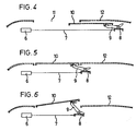
- a direct current drive motor 6 which can be reversed in its direction of rotation, serves to actuate a sliding / tilting roof, which has a cover 10, by means of which a roof opening 11 of a vehicle, of which in the FIGS. 4, 5 and 6 only the roof 12 is indicated, closed or at least partially exposed.
- the drive motor 6 adjusts in a manner known per se (DE-AS 19 33 991) via a pressure-resistant drive cable 7 a transport bridge 8 which is guided so as to be displaceable in the longitudinal direction of the vehicle.
- a deployment lever 9 is pivotally mounted. Depending on the displacement of the transport bridge 8, the deployment levers 9 are caused to pivot in a manner not shown.
- the design is such that, starting from the closed position illustrated in FIG. 5, the cover 10 can either be lowered and pushed backwards (FIG. 4) or its rear edge can be extended into a ventilation position over the surface of the fixed roof 12 (FIG. 6).
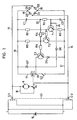
- a pole-reversal actuation switch S1 which has two changeover contacts S11 and S12 mechanically coupled to one another.
- lines 13 and 14 connected to the changeover contacts S11 and S12 are optionally connected to the positive and negative sides or to the negative and positive sides of a direct voltage source 15, for example in the form of a motor vehicle battery.
- the changeover contacts S11 and S12 are automatically in the in the Figs. 1 and 2 drawn 0 position reset.
- the drive motor 6 lies between the lines 13, 14 in series with a contact rs of a relay RS.
- the relay contact rs disconnects the motor circuit when the relay RS has dropped out and closes an inductive braking circuit which leads via a line 16.
- the relay RS is a normal DC relay that closes the switching contact rs with respect to the motor circuit when a voltage sufficient for its actuation is present and brings the contact rs into a position that interrupts the motor circuit (FIG. 1) when the relay is connected RS applied voltage drops to a value below which the holding current of the relay falls below. If the switch contact rs is in its working position closing the motor circuit, voltage is applied with one or the other polarity by actuating the switch S1 and the drive motor 6 and accordingly the motor is made to run in one or the other direction of rotation.
- S12 of the changeover switch S1 is together with the control circuit (line 17) of the relay RS a transistor T1, T2 and T3 having relay actuation stage via a full wave rectifier bridge, consisting of diodes D1, D2, D3 and D4, in parallel to that Motor circuit connected.
- a line 19 is connected to the positive output 18 of the full-wave rectifier bridge, while a line 21 is connected to the negative output 20 of the bridge.
- the base of transistor T1 is connected to line 19 via a series circuit comprising a capacitor C1 and a resistor R1, and to line 21 via a capacitor C2.
- the collector of transistor T1 is connected to line 10 via a resistor R2; the emitter of transistor R1 is connected to line 21 via a resistor R3. If necessary, the emitter of the transistor T1 can also be connected directly to the line 21, ie the resistor R3 can be omitted.
- the base of transistor T2 is connected to the collector of transistor T1 via a resistor R7.
- the collector of the transistor T2 is connected via a resistor R4 to the coupling point 22 between the capacitor C1 and the resistor R1 and via a resistor R5 to the line 19.
- the emitter of transistor T2 is in direct connection with line 21.
- the base of transistor T3 is connected to the collector of transistor T2 via a resistor R6.
- the emitter of transistor T3 is connected to line 21 via a diode D5, which has the same polarity as the polarity of the emitter diode of transistor T3.
- the collector of the transistor T3 is connected to the base of transistor T1 via a diode D6. It is also connected to a coupling point 23 between the winding of the relay RS and a position detection switch S2.
- One side of the relay winding is connected directly to line 19 via line 17.
- the other side of the relay winding can be connected to line 21 via switch S2.
- the position detection switch S2 is actuated as a function of the position of the cover 10 in such a way that it opens in a predetermined reference position of the cover 10 and closes in all other cover positions. In the case of the sliding / lifting roof illustrated by way of example, the reference position is the closed position of the cover shown in FIG. 5.
- a diode D7 is connected in parallel with the relay winding.
- the transistor T2 in turn generates a high at its output (collector), which is coupled to the base of the transistor T3 via the resistor R6.
- the transistor T3 turns on and pulls the relay RS.
- the collector of transistor T2 leads the high back to the base of transistor T1 via the series connection of resistors R4 and R1.
- the resistors R4 and R1 form a self-holding loop, which keeps the relay actuation stage in the set state after the setting, until a resetting described below takes place.
- the motor circuit is closed via the switch contact rs of the relay. The motor starts in the direction of rotation specified by the actuation direction of the switch S1 and adjusts the cover 10 via the drive cable 7.
- the position detection switch S2 is closed due to the cover movement. This keeps the relay RS energized.
- a reset signal (low) is coupled back from the coupling point 23 via the diode D6 and a line 24 to the base of the transistor T1.
- the line 24 forms a static input of the relay actuation stage T1, T2, T3.
- the diode D5 can also be located in the collector circuit of the transistor T3.
- the resistors R4 and R1 serving for the feedback of the setting function should preferably be dimensioned in a ratio of approximately 1: 2 to 1: 3.
- the resistor R6 should have a relatively high value. It is thereby achieved that the current flowing through transistor T2 is substantially larger than the current flowing to the base of transistor T3. These currents are preferably in a mutual relationship on the order of 10: 1.
- the capacitor C2 serves to debounce the position detection switch S2.
- the diode D7 acts as a quenching diode for the relay RS.
- the relay actuation stage T1, T2, T3 is reset.
- the motor 6 is controlled in any direction of rotation only by the reversing switch S1. If the cover 10 moves into the reference position, it opens the position detection switch S2.
- the relay RS is dropped. Contact rs breaks the motor circuit.
- the motor winding is short-circuited via line 16 for inductive braking.
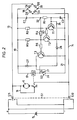
- FIG. 2 shows a circuit design in which the collector-emitter path of the transistor T3 and the position detection switch S2 are connected in series.
- the switch S2 has a changeover contact 26 which, as long as the cover 10 is in the reference position (closed position), bears against a contact 27 and thereby places the collector-emitter path of the transistor T3 in series with the winding of the relay RS.
- the changeover contact 26 switches to a contact 28 connected to the line 21 after the cover 10 has left the reference position.
- a reset signal goes to the transistor T1 via the diode D6 and the line 24.
- the transistor T3 is blocked via the transistors T1 and T2. If the actuation switch S1 is now actuated in one or the other direction, the transistor logic stage formed by the transistors T1 and T2 is set in the manner explained with reference to FIG. 1 such that the transistor T3 switches on. Consequently current flows through the series circuit, which consists of the winding of the relay RS, the position detection switch S2 and the collector-emitter path of the transistor T3.
- the relay RS picks up; Motor 6 is switched on via relay contact rs.
- the motor 6 runs until either the actuation switch S1 returns to its zero position or the cover reaches the closed position and the position detection switch S2 switches over. In the latter case, a reset signal is again sent to the base of transistor D1 via diode D6.
- the diode D5 and the resistor R3 can be omitted.
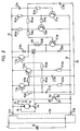
- the relay actuation stage has two circuit units arranged in mirror symmetry, which are similar to the relay actuation stage according to FIG. 1.
- the lines 19, 21 are directly connected to the changeover contacts S11 and S12 of the reversing pole actuation switch S1, omitting the full-wave rectifier bridge D1, D2, D3, D4.
- the position detection switch S2 has as a switching element a changeover contact 26 which, in the reference position of the cover 10 - in the exemplary embodiment according to FIGS. 4 to 6, in the closed position of FIG.
- the changeover contact 26 is connected to a line 29 which is connected to a dynamic input of the two circuit units T1a, T2a, T3a and T1b, T2b, T3b, which leads via a capacitor C3a and C3b.
- the diodes D5, D6 and D7 of the arrangement according to FIG. 1 are omitted.
- One side of the winding of the relay RS is connected to line 21 via the collector-emitter path of transistor T3a, while the other side of the relay winding is connected to line 19 via the collector-emitter path of transistor T3b.
- a diode D8b and D8a are connected in parallel to the collector-emitter paths of the transistors T3a and T3b. Parallel to the winding of the relay RS are two Z-diodes D9 and D10 connected in series with opposite poles.
- the collector of transistor T1a is connected to the base of transistor T2a via a resistor R7a. In an analogous manner, a resistor R7b is connected between the collector of transistor T1b and the base of transistor T2b.
- the drive motor moves the transport bridge 8 to the rear when the changeover contact S11 is connected to the positive and the changeover contact S12 to the negative terminal of the current source 15, while the transport bridge 8 is moved forward when the changeover contact S11 with the negative side and the switch contact S12 is connected to the positive side of the current source 15.
- the cover 19 is initially in the reference position (closed position according to FIG. 5) and from there should be pushed back according to Fig. 4. In the closed position of the cover 10, the changeover contact 26 of the position detection switch S2 is in contact with the contact 27. If the actuation switch S1 in FIG.
- the right-hand circuit unit of the relay actuation stage in FIG. 3 has a brief positive pulse based on the transistor T1a.
- the base of this transistor is briefly pulled high.
- the resulting low on the collector of transistor T1a is coupled to the base of transistor T2a via resistor R7a.
- the collector of transistor T2a goes high. This signal is applied to the base of transistor T3a, which consequently turns on.
- the high is fed back from the collector of transistor T2a through the self-holding loop having resistors R4a and R1a to the base of transistor T1a, so that the set state triggered by the positive pulse at the base of transistor T1a is maintained.
- Current flows from the positive side of the DC voltage source 15 via the changeover contact S11, the diode D8a, the winding of the relay RS and the collector-emitter path of the transistor T3a to the line 21, and from there via the changeover contact S12 to the negative side of the DC voltage source 15.
- the relay RS picks up and is held in the tightened state.
- the relay switch contact rs closes the circuit of the drive motor 6. Via the Motor 6 flows in the direction indicated by arrow 3o.
- the motor 6 starts.
- the transport bridge 8 is adjusted to the rear via the drive cable 7.
- the lid 1o is lowered and pushed back according to Fig.4.
- the circuit unit illustrated in FIG. 3 on the left-hand side with the transistors T1b, T2b and T3b is deactivated because the high potential on line 19 and the low potential on line 21 make transistors T1b, T2b and T3b are blocked.
- the position detection switch S2 switches over; the changeover contact 26 is switched from the contact 27 to the contact 28.
- the lid 10 can be stopped in any intermediate position by moving the actuation switch S1 to the 0 position shown in FIG. 3 and thereby de-energizing the drive motor 6.
- the actuation switch S1 is again adjusted so that the switch 19 contacts the line 19 with the positive one and line 21 is connected to the negative side of voltage source 15 via changeover contact S12.
- the changeover contact 26 of the position detection switch S2 which is now connected to the contact 28, the base of the transistor T1a is acted upon by a positive pulse via the dynamic input formed by the capacitor C3a, so that the relay RS is attracted in the manner described above and is kept dressed.
- the line 19 is connected to the negative side of the DC voltage source 15 via the changeover contact S11, while the line 21 is connected to the positive side of the voltage source 15 via the changeover contact S12.
- a low pulse is sent to the base of the transistor T2b via the dynamic input having the transistor C3b.
- the low at the base of transistor T2b leads to a high at the collector of this transistor, which is transferred to the base of transistor T3b via resistor R6b.
- the transistor T3b turns on.
- a reset signal in the form of a positive pulse goes via the changeover contact S12, the position detection switch S2 and the line 29 via the dynamic input having the capacitor C3b of the circuit unit on the left in FIG. 3 to the base of the transistor T2b.
- the transistor T3b is blocked.
- the relay RS is dropped.
- the changeover contact rs disconnects the motor circuit and activates the inductive brake via line 16. The cover 1o is stopped immediately.
- the low signal from the output of transistor T2b is fed back through the resistors R4b and R1b to the base of transistor T1b, whereby the left circuit unit of the relay actuation stage, which has the transistors T1b, T2b and T3b, is held in the reset state.
- the transistor T2b is also de-energized.
- the actuation switch S1 in FIG. 3 is switched down.
- a set signal in the form of a short-term positive pulse goes from the positive side of the DC voltage source 15 via the changeover contact R12 to the dynamic input leading via the capacitor C1b.
- the transistor T1b is turned on.
- the low on the collector of the transistor T1b causes a high at the collector of transistor T2b.
- This signal is fed back through the resistors R4b and R1b to the base of the transistor T1b and also turns on the transistor T3b.
- Current flows from line 21 via diode D8b, the winding of relay RS and the controlled transistor T3b to line 19.
- the motor circuit is closed via relay contact rs.
- the current flows through the motor 6 in the direction of the arrow 31.
- the transport bridge 8 is pulled further forward via the drive cable 7.
- the lid 10 is issued. After moving off, the changeover contact 26 of the position detection switch S2 is changed over from the contact 27 to the contact 28.
- the transport bridge 8 is based on the position shown in FIG. 6 or an intermediate position between the fully extended position and the Closed position moved back towards the closed position. If the closed position is reached, the position detection switch S2 switches from the contact 28 to the contact 27. Via the changeover contact S12, the position detection switch S2, the line 29 and the capacitor C3a, a short-term negative pulse acting as a reset signal goes to the base of the transistor T1a. This transistor is blocked. The high at the collector of transistor T1a turns on transistor T2a. The low signal at the collector of transistor T2a blocks transistor T3a via resistor R6a.
- the relay RS is dropped. over the relay contact rs the motor circuit is interrupted.
- the lid 1o is stopped in the closed position.
- the diodes D8a and D8b bridge the respectively blocked parallel-connected transistor T3b and T3a.
- the diode D8a is poled in the same direction as the emitter diode of the transistor T3a.
- the Zener diodes D9 and D1o ensure bipolar spark suppression of the induction voltage when the relay RS drops out.
- npn transistors are provided. However, it goes without saying that the circuits can also be constructed in an analog manner with pnp transistors.
- the exemplary embodiments according to FIGS. 1 to 3 use discrete circuit components. Instead, standardized integrated circuits can in principle also be used. A discrete circuit structure has the advantage that higher temperatures and higher voltages or voltage peaks can be tolerated. High currents can also be processed with discrete circuit components, thereby eliminating faults that can occur in motor vehicle bowls.
- the disclosed circuit design further allows miniaturization through the use of SMD components. In the idle state, ie with the actuation switch S1 in its 0 position, the entire circuit is de-energized in the case of both embodiments, so that no interference can be coupled in either.
- the embodiments according to FIGS. 1 and 2 also have the advantage that the electronic relay actuation stage is made active only for starting from the reference position. As a result, the cover 1o which is brought out of the closed position according to FIG. 5 (pushed back or opened) can always be closed by manually operating the switch S1.
- the actuating device explained is not limited to a special type of drive (transport bridge 8, deployment lever 9), but can also be used in conjunction with any other drives.
- the actuator is also suitable for any roof design, e.g. for simple sliding roofs, simple lifting roofs or so-called spoiler or top ridge roofs, in which the cover is swung out of the closed position and then pushed back over the fixed roof surface. In the latter case, the fully extended position of the cover in its front end position is expediently used as the reference position.
Landscapes
- Engineering & Computer Science (AREA)
- Mechanical Engineering (AREA)
- Power-Operated Mechanisms For Wings (AREA)
- Control Of Direct Current Motors (AREA)
- Stopping Of Electric Motors (AREA)
Claims (16)
- Dispositif d'actionnement d'éléments mobiles (10) pour la fermeture d'ouvertures telles que des fenêtres, des portes ou des ouvertures de toit, dans les véhicules automobiles, avec un moteur d'entraînement (6) à courant continu, dont le sens de rotation peut être inversé, pour l'entraînement de l'élément mobile, avec un commutateur de commande-inverseur (S1) se trouvant dan le circuit électrique du moteur pour appliquer une tension continue au circuit électrique du moteur avec une polarité correspondant, au choix, à l'un ou l'autre sens de rotation du moteur, avec un relais (RS) qui présente un contact de commutation (rs) se trouvant dans le circuit électrique du moteur en série avec le contacteur de commande-inverseur, ainsi qu'avec un étage de reconnaissance de position (S2) se trouvant en liaison avec le circuit électrique de commande du relais pour actionner le relais dans une position de référence prédéterminée de l'élément mobile dans le but d'une mise automatique à l'arrêt du moteur d'entraînement dans cette position de référence par ouverture du contact, dispositif dans lequel il est prévu comme relais (RS) un relais à courant continu, qui ferme le contact (rs) quand on lui applique un premier niveau de tension sur son circuit électrique de commande et dans lequel un étage électronique d'actionnement du relais (T1, T2, T3; T1a, T2a, T3a; T1b, T2b, T3b) est relié au circuit de commande du relais (RS) avec mémorisation qui ensuite est actionné par un signal de mise en état, quand l'élément mobile (10) se trouve dans la position de référence, par la fermeture du commutateur de commande-inverseur (S1) dans l'un ou l'autre sens, signal de mise en état en raison duquel l'étage d'actionnement du relais applique sur le circuit électrique de commande de relais le premier niveau de tension, dispositif d'actionnement caractérisé en ce que l'étage d'actionnement du relais (T1, T2, T3; T1a, T2a, T3a; T1b, T2b, T3b) est maintenu dans la position établie en fonction de la position de l'élément mobile (couvercle 10) jusqu'à ce que l'élément mobile ait quitté la position de référence.
- Dispositif d'actionnement selon la revendication 1, caractérisé en ce que le circuit de départ de l'étage d'actionnement du relais est monté en série avec l'étage de reconnaissance de position (commutateur S2 de reconnaissance de position).
- Dispositif d'actionnement selon la revendication 1, caractérisé en ce que, le circuit de départ de l'étage d'actionnement du relais est monté en parallèle à l'étage de reconnaissance de position (commutateur de reconnaissance de position 52).
- Dispositif d'actionnement selon l'une des revendications précédentes, caractérisé en ce que l'étage de reconnaissance de position (commutateur de reconnaissance de position S2) laisse retomber le relais (RS), quand l'élément mobile (couvercle 10) arrive à la position de référence, et en ce que le contact (rs) qui met sous courant et hors courant le moteur d'entraînement (6) est constitué comme un contacteur.
- Dispositif d'actionnement selon l'une des revendications précédentes, caractérisé en ce que l'étage de reconnaissance de position présente un commutateur (S2), qui, quand l'élément mobile se trouve dans la position de référence (couvercle 10) prend un première position de commutation et quand l'élément mobile sort de la position de référence prend une deuxième position de commutation.
- Dispositif d'actionnement selon la revendication 5, caractérisé en ce que le commutateur de reconnaissance de position (S2) est monté directement en série avec l'enroulement du relais (RS).
- Dispositif d'actionnement selon la revendication 5, caractérisé en ce que le commutateur de reconnaissance de position (S2) agit sur le relais (RS) via l'étage d'actionnement électronique du relais.
- Dispositif d'actionnement selon l'une des revendications précédentes, caractérisé en ce que l'étage d'actionnement du relais présente au moins une entrée dynamique (condensateur C₁; condensateurs C1a, C1b) se trouvant en liaison avec le commutateur de commande-inverseur (S1).
- Dispositif d'actionnement selon l'une des revendications précédentes, caractérisé en ce que l'étage d'actionnement du relais est pourvu d'une boucle à auto-maintien (résistances R1, R4; R1a, R4a, R1b, R4b) qui maintient dans l'état établi l'étage d'actionnement du relais après la mise en état au moins jusqu'à ce que l'élément mobile (couvercle 10) ait quitté la position de référence.
- Dispositif d'actionnement selon l'une des revendications précédentes, caractérisé en ce que l'étage d'actionnement du relais est raccordé en même temps que le circuit de commande du relais (RS) au commutateur de commande- inverseur (S1) en parallèle au circuit électrique du moteur par l'intermédiaire d'un redresseur à pleine onde (diodes D1, D2, D3, D4).
- Dispositif d'actionnement selon les revendications 2 et 6, caractérisé en ce que le commutateur de reconnaissance de position (S2) présente un contact de commutation (26), qui, quand l'élément mobile (couvercle 10) se trouve dans la position de référence, met en série avec l'enroulement du relais (RS) le circuit de départ de l'étage d'actionnement du relais et qui, quand l'élément mobile a quitté la position de référence, ferme un circuit de maintien du relais passant par le commutateur de commande-inverseur (S1).
- Dispositif d'actionnement selon les revendications 6 à 10, caractérisé en ce que le commutateur de reconnaissance de position (S2), quand l'élément mobile (10) se trouve dans la position de référence, est ouvert et en ce que le commutateur de reconnaissance de position est relié à une entrée statique (conducteur 24) de l'étage d'actionnement du relais par une diode (D6), qui est maintenue bloquée quand le commutateur de reconnaissance de position est ouvert.
- Dispositif d'actionnement selon la revendication 12, caractérisé en ce qu'un organe de compensation de dérive de température (Diode D5) se trouve dans le circuit de départ de l'étage d'actionnement du relais, organe qui, quand le commutateur de reconnaissance de position (S2) est ouvert, maintient une tension de blocage suffisante pour un blocage sûr de la diode (D1) indépendamment des variations de température.
- Dispositif d'actionnement selon l'une des revendications 1 à 9 et 11, caractérisé en ce que l'étage d'actionnement du relais présente deux unités de commutation sensiblement symétriques, dont l'une est excitée lors de la fermeture du commutateur de commande-inverseur (S1) dans l'un des sens de polarisation et l'autre est excitée lors de la fermeture du commutateur de commande-inverseur dans l'autre sens de polarisation.
- Dispositif d'actionnement selon la revendication 14, caractérisé en ce que chacune des deux unités de commutation présente une entrée (condensateurs C10, C1b) dynamique directement reliée au commutateur de commande-inverseur (S1) et une entrée de remise à l'état (condensateurs C3a, C3b) dynamique raccordée à l'étage de reconnaissance de position (commutateur de reconnaissance de position S2).
- Dispositif d'actionnement selon la revendication 14 ou 15, caractérisé en ce qu'un commutateur à semi-conducteur (transistor T3a) commandé du côté sortie de l'une des unités de commutation un commutateur à semi-conducteur (transistor T3b) commandé du côté sortie de l'autre unité de commutation polarisé en sens opposé sont mis en circuit en série avec l'enroulement dr relais (RS) et en ce que, au moins une diode (D8b, D8a) anti-parallèle est mise en circuit aux deux commutateurs commandés du côté sortie.
Applications Claiming Priority (2)
| Application Number | Priority Date | Filing Date | Title |
|---|---|---|---|
| DE3730034 | 1987-09-08 | ||
| DE3730034 | 1987-09-08 |
Publications (3)
| Publication Number | Publication Date |
|---|---|
| EP0306950A2 EP0306950A2 (fr) | 1989-03-15 |
| EP0306950A3 EP0306950A3 (en) | 1990-04-04 |
| EP0306950B1 true EP0306950B1 (fr) | 1992-04-01 |
Family
ID=6335479
Family Applications (1)
| Application Number | Title | Priority Date | Filing Date |
|---|---|---|---|
| EP88114690A Expired - Lifetime EP0306950B1 (fr) | 1987-09-08 | 1988-09-08 | Dispositif d'actionnement d'éléments mobiles pour la fermeture d'ouvertures dans des véhicules automobiles |
Country Status (7)
| Country | Link |
|---|---|
| US (1) | US4910445A (fr) |
| EP (1) | EP0306950B1 (fr) |
| JP (1) | JP2723918B2 (fr) |
| DE (1) | DE3869703D1 (fr) |
| FR (1) | FR2620162B3 (fr) |
| GB (1) | GB2209636B (fr) |
| NL (1) | NL8802200A (fr) |
Families Citing this family (31)
| Publication number | Priority date | Publication date | Assignee | Title |
|---|---|---|---|---|
| DE3930053A1 (de) * | 1989-09-08 | 1991-03-21 | Webasto Ag Fahrzeugtechnik | Betaetigungsvorrichtung fuer ein luefterdach eines fahrzeuges |
| JPH0345098U (fr) * | 1989-09-11 | 1991-04-25 | ||
| NL9002199A (nl) * | 1990-10-10 | 1992-05-06 | Vermeulen Hollandia Octrooien | Inrichting voor het bedienen van het dakpaneel van een schuifdak of een schuif/hefdak van een motorvoertuig. |
| NL9002198A (nl) * | 1990-10-10 | 1992-05-06 | Vermeulen Hollandia Octrooien | Inrichting voor het bedienen van het dakpaneel van een schuifdak of een schuif/hefdak van een motorvoertuig. |
| DE9106410U1 (fr) * | 1991-05-24 | 1992-09-24 | Dictator Technik Dr. Wolfram Schneider & Co Verwaltungs- Und Beteiligungsgesellschaft, 8902 Neusaess, De | |
| JP2602999Y2 (ja) * | 1991-12-26 | 2000-02-07 | 株式会社村上開明堂 | 電動格納ドアミラーの制御装置 |
| DE4323946C2 (de) * | 1993-07-16 | 1999-02-25 | Webasto Karosseriesysteme | Antriebsvorrichtung für ein verstellbares Fahrzeugteil |
| US6056352A (en) * | 1994-07-05 | 2000-05-02 | Asc Incorporated | Sunroof assembly for an automotive vehicle and control system for operating a sunroof assembly |
| WO1996001192A1 (fr) * | 1994-07-05 | 1996-01-18 | Asc Incorporated | Ensemble toit ouvrant pour automobile et son systeme de commande |
| US5961177A (en) * | 1994-07-05 | 1999-10-05 | Asc Incorporated | Sunroof assembly drain trough for an automotive vehicle |
| US5746475A (en) * | 1995-06-07 | 1998-05-05 | Asc Incorprated | Drive mechanism for an automotive vehicle sunroof assembly |
| JPH0878506A (ja) * | 1994-09-05 | 1996-03-22 | Canon Inc | 位置決め制御装置 |
| DE19523209C1 (de) * | 1995-06-27 | 1996-08-08 | Webasto Karosseriesysteme | Betätigungsvorrichtung für bewegbare Teile zum Schließen von Öffnungen in Fahrzeugen |
| IT1285269B1 (it) * | 1996-02-27 | 1998-06-03 | Roltra Morse Spa | Dispositivo di comando di un motore elettrico, in particolare per l'azionamento di un tetto apribile di un veicolo. |
| KR100268493B1 (ko) * | 1996-09-23 | 2000-11-01 | 윤종용 | 알.에이.아이.디(raid)시스템의 공기순환장치 및 그 방법 |
| DE19732095A1 (de) * | 1997-07-25 | 1999-01-28 | Bosch Gmbh Robert | Schaltungsanordnung zum Ansteuern eines Motors mit einer Überlasterkennungseinrichtung |
| US6129413A (en) * | 1997-11-13 | 2000-10-10 | Asc Incorporated | Powered dual panel sunroof |
| DE19834823C1 (de) * | 1998-08-01 | 1999-07-08 | Webasto Karosseriesysteme | Vorrichtung zum Verstellen von bewegbaren Teilen an Fahrzeugen |
| DE19842337A1 (de) * | 1998-09-16 | 2000-03-23 | Mannesmann Vdo Ag | Betätigungseinrichtung für ein Verdeck eines Cabrios |
| US6404155B1 (en) * | 1999-11-12 | 2002-06-11 | Taiko Device, Ltd. | DC motor drive circuit |
| DE10006234A1 (de) * | 2000-02-11 | 2001-08-23 | Siemens Ag | Verfahren und Vorrichtung zum Ansteuern einer elektrischen Betätigungseinheit |
| JP3581838B2 (ja) * | 2001-05-25 | 2004-10-27 | 株式会社村上開明堂 | 電動格納式ドアミラーの制御方式 |
| US20050280293A1 (en) * | 2004-06-17 | 2005-12-22 | Macnee Arthur L Iii | Automotive vehicle open air system |
| US7163260B2 (en) * | 2004-06-17 | 2007-01-16 | Asc Incorporated | Automotive vehicle open air system |
| US20050283280A1 (en) * | 2004-06-17 | 2005-12-22 | Evans Alan F Jr | Vehicle sensing system |
| WO2006063303A1 (fr) * | 2004-12-09 | 2006-06-15 | Won-Door Corporation | Procede et appareil de commande de moteur utilisant des relais |
| US20060145518A1 (en) * | 2005-01-04 | 2006-07-06 | Evans Alan F Jr | Control system for a vehicle roof |
| US7527328B2 (en) * | 2007-05-24 | 2009-05-05 | Specialty Vehicle Acquisition Corp. | Modular roof system for automotive vehicle |
| US7938483B2 (en) * | 2007-05-24 | 2011-05-10 | Specialty Vehicle Acquisition Corp. | Movable vehicular roof |
| CN101289918B (zh) * | 2008-05-13 | 2012-05-30 | 王国华 | 机动车落水车窗自启装置 |
| CN105610349A (zh) * | 2016-01-14 | 2016-05-25 | 苏州成科自控设备有限公司 | 一种快速的执行器制动装置 |
Family Cites Families (12)
| Publication number | Priority date | Publication date | Assignee | Title |
|---|---|---|---|---|
| AT293898B (de) * | 1968-05-16 | 1971-10-25 | Webasto Werk Baier Kg W | Fahrzeugschiebedach |
| GB1261846A (en) * | 1969-07-04 | 1972-01-26 | Webasto Werk Baier Kg W | Improvements in and relating to slidable roofs for vehicles |
| DE2100336C3 (de) * | 1971-01-05 | 1978-07-13 | Webasto-Werk W. Baier Gmbh & Co, 8031 Stockdorf | Betätigungsvorrichtung für bewegbare Teile zum Schließen von Öffnungen |
| GB1466507A (en) * | 1974-11-19 | 1977-03-09 | Baier W | Operation of movable part of vehicle coachwork |
| DE2704899A1 (de) * | 1977-02-05 | 1978-08-10 | Webasto Werk Baier Kg W | Betaetigungsvorrichtung fuer einen ausstellbaren schiebedeckel |
| DE2820330C2 (de) * | 1978-05-10 | 1986-05-28 | SWF Auto-Electric GmbH, 7120 Bietigheim-Bissingen | Schaltanordnung für einen elektrischen Fensterheberantrieb oder dergleichen |
| JPS56123783A (en) * | 1980-02-29 | 1981-09-29 | Nippon Denso Co Ltd | Control unit for load driving |
| JPS5825035A (ja) * | 1981-08-07 | 1983-02-15 | Hitachi Ltd | カラ−ブラウン管の製造方法 |
| US4502726A (en) * | 1982-09-27 | 1985-03-05 | Asc Incorporated | Control apparatus for pivotal-sliding roof panel assembly |
| DE3411001A1 (de) * | 1984-03-24 | 1985-09-26 | Audi AG, 8070 Ingolstadt | In ein automobil einbaubare schaltungsanordnung |
| DE3612150A1 (de) * | 1985-05-04 | 1986-11-06 | Webasto-Werk W. Baier GmbH & Co, 8035 Gauting | Vorrichtung zum betaetigen eines fahrzeugdaches |
| NL8700159A (nl) * | 1987-01-23 | 1988-08-16 | Vermeulen Hollandia Octrooien | Bedieningsinrichting voor een beweegbaar deel, bestemd voor het openen en sluiten van een opening, in het bijzonder een voertuigschuif/hefdak. |
-
1988
- 1988-07-18 FR FR888809677A patent/FR2620162B3/fr not_active Expired
- 1988-08-30 JP JP63217785A patent/JP2723918B2/ja not_active Expired - Lifetime
- 1988-09-06 NL NL8802200A patent/NL8802200A/nl not_active Application Discontinuation
- 1988-09-07 GB GB8820995A patent/GB2209636B/en not_active Expired - Fee Related
- 1988-09-08 EP EP88114690A patent/EP0306950B1/fr not_active Expired - Lifetime
- 1988-09-08 DE DE8888114690T patent/DE3869703D1/de not_active Expired - Fee Related
-
1989
- 1989-03-08 US US07/320,555 patent/US4910445A/en not_active Expired - Lifetime
Also Published As
| Publication number | Publication date |
|---|---|
| FR2620162B3 (fr) | 1989-12-15 |
| EP0306950A2 (fr) | 1989-03-15 |
| DE3869703D1 (de) | 1992-05-07 |
| GB2209636B (en) | 1991-12-04 |
| FR2620162A1 (fr) | 1989-03-10 |
| EP0306950A3 (en) | 1990-04-04 |
| GB2209636A (en) | 1989-05-17 |
| NL8802200A (nl) | 1989-04-03 |
| JP2723918B2 (ja) | 1998-03-09 |
| JPS6474091A (en) | 1989-03-20 |
| GB8820995D0 (en) | 1988-10-05 |
| US4910445A (en) | 1990-03-20 |
Similar Documents
| Publication | Publication Date | Title |
|---|---|---|
| EP0306950B1 (fr) | Dispositif d'actionnement d'éléments mobiles pour la fermeture d'ouvertures dans des véhicules automobiles | |
| DE3832941C2 (fr) | ||
| DE19517958A1 (de) | Motorantriebsvorrichtung für ein Kraftfahrzeug | |
| EP1941120B1 (fr) | Mecanisme d'entrainement destine a actionner un battant mobile, en particulier une porte | |
| DE3116737A1 (de) | Schaltanordnung fuer einen aus einer spannungsquelle gespeisten, drehrichtungsumkehrbaren elektromotor zum antrieb einer kombinierten fensterhebe- und tuerverriegelungsanlage in kfz. | |
| DE4344378A1 (de) | Einrichtung zum Antreiben und Steuern eines Motors | |
| DE4119284A1 (de) | Steuervorrichtung fuer fenster mit elektrischem fensterheber | |
| DE10260588A1 (de) | Steuereinrichtung für ein Schließelement und Verfahren zur Begrenzung von Stellungsabweichungen eines Schließelements | |
| DE4203659A1 (de) | Blockiererkennung von gleichstrommotoren | |
| DE3830555A1 (de) | Betaetigungsvorrichtung fuer bewegbare teile zum schliessen von oeffnungen in fahrzeugen | |
| DE4030402A1 (de) | Steuervorrichtung fuer elektrische fensterscheibenheber | |
| EP1713997B1 (fr) | Montage electrique | |
| EP1244564B1 (fr) | Circuit electrique pour la commande d'un moteur electrique dans un vehicule | |
| DE3730281C2 (fr) | ||
| EP0416384B1 (fr) | Dispositif de commande pour un toit à ventilation d'un véhicule | |
| DE4012547A1 (de) | Schaltervorrichtung | |
| DE10048293A1 (de) | Elektrisches Steuergerät | |
| DE2902175C2 (de) | Einrichtung zur Steuerung eines Wischermotors in einem Kraftfahrzeug | |
| EP0978401B1 (fr) | Dispositif d' actionnement pour déplacer des éléments mobiles pour véhicules au moyen d'un moteur de positionnement court-circuitable | |
| DE102019208065B4 (de) | Schaltung zur Steuerung eines Elektromotors eines Fensterhebers eines Fahrzeugs, Fahrzeug und Verfahren | |
| DE2150460A1 (de) | Steuerschaltung fuer Hebemechanismus eines Kraftfahrzeugfensters | |
| DE19523209C1 (de) | Betätigungsvorrichtung für bewegbare Teile zum Schließen von Öffnungen in Fahrzeugen | |
| DE10108946A1 (de) | Verfahren zur Steuerung eines Elektromotors | |
| DE10000530A1 (de) | Elektrische Schaltungsanordnung | |
| DE102004041466B4 (de) | Elektromotorischer Stellantrieb mit Steuereinheit für Zwischenposition und Steuerverfahren |
Legal Events
| Date | Code | Title | Description |
|---|---|---|---|
| PUAI | Public reference made under article 153(3) epc to a published international application that has entered the european phase |
Free format text: ORIGINAL CODE: 0009012 |
|
| AK | Designated contracting states |
Kind code of ref document: A2 Designated state(s): DE FR GB NL |
|
| PUAL | Search report despatched |
Free format text: ORIGINAL CODE: 0009013 |
|
| AK | Designated contracting states |
Kind code of ref document: A3 Designated state(s): DE FR GB NL |
|
| 17P | Request for examination filed |
Effective date: 19900615 |
|
| 17Q | First examination report despatched |
Effective date: 19901203 |
|
| GRAA | (expected) grant |
Free format text: ORIGINAL CODE: 0009210 |
|
| AK | Designated contracting states |
Kind code of ref document: B1 Designated state(s): DE FR GB NL |
|
| ET | Fr: translation filed | ||
| REF | Corresponds to: |
Ref document number: 3869703 Country of ref document: DE Date of ref document: 19920507 |
|
| GBT | Gb: translation of ep patent filed (gb section 77(6)(a)/1977) | ||
| PLBE | No opposition filed within time limit |
Free format text: ORIGINAL CODE: 0009261 |
|
| STAA | Information on the status of an ep patent application or granted ep patent |
Free format text: STATUS: NO OPPOSITION FILED WITHIN TIME LIMIT |
|
| 26N | No opposition filed | ||
| ITF | It: translation for a ep patent filed |
Owner name: BUGNION S.P.A. |
|
| PGFP | Annual fee paid to national office [announced via postgrant information from national office to epo] |
Ref country code: FR Payment date: 19990917 Year of fee payment: 12 |
|
| PGFP | Annual fee paid to national office [announced via postgrant information from national office to epo] |
Ref country code: NL Payment date: 19990921 Year of fee payment: 12 |
|
| PG25 | Lapsed in a contracting state [announced via postgrant information from national office to epo] |
Ref country code: NL Free format text: LAPSE BECAUSE OF NON-PAYMENT OF DUE FEES Effective date: 20010401 |
|
| PG25 | Lapsed in a contracting state [announced via postgrant information from national office to epo] |
Ref country code: FR Free format text: LAPSE BECAUSE OF NON-PAYMENT OF DUE FEES Effective date: 20010531 |
|
| NLV4 | Nl: lapsed or anulled due to non-payment of the annual fee |
Effective date: 20010401 |
|
| REG | Reference to a national code |
Ref country code: FR Ref legal event code: ST |
|
| REG | Reference to a national code |
Ref country code: GB Ref legal event code: IF02 |
|
| PGFP | Annual fee paid to national office [announced via postgrant information from national office to epo] |
Ref country code: GB Payment date: 20020819 Year of fee payment: 15 |
|
| PGFP | Annual fee paid to national office [announced via postgrant information from national office to epo] |
Ref country code: DE Payment date: 20020925 Year of fee payment: 15 |
|
| PG25 | Lapsed in a contracting state [announced via postgrant information from national office to epo] |
Ref country code: GB Free format text: LAPSE BECAUSE OF NON-PAYMENT OF DUE FEES Effective date: 20030908 |
|
| PG25 | Lapsed in a contracting state [announced via postgrant information from national office to epo] |
Ref country code: DE Free format text: LAPSE BECAUSE OF NON-PAYMENT OF DUE FEES Effective date: 20040401 |
|
| GBPC | Gb: european patent ceased through non-payment of renewal fee |
Effective date: 20030908 |