EP0304873B1 - Milieu d'enregistrement magnéto-optique - Google Patents
Milieu d'enregistrement magnéto-optique Download PDFInfo
- Publication number
- EP0304873B1 EP0304873B1 EP88113711A EP88113711A EP0304873B1 EP 0304873 B1 EP0304873 B1 EP 0304873B1 EP 88113711 A EP88113711 A EP 88113711A EP 88113711 A EP88113711 A EP 88113711A EP 0304873 B1 EP0304873 B1 EP 0304873B1
- Authority
- EP
- European Patent Office
- Prior art keywords
- layer
- magneto
- optical recording
- recording medium
- under layer
- Prior art date
- Legal status (The legal status is an assumption and is not a legal conclusion. Google has not performed a legal analysis and makes no representation as to the accuracy of the status listed.)
- Expired - Lifetime
Links
Images


Classifications
-
- G—PHYSICS
- G11—INFORMATION STORAGE
- G11B—INFORMATION STORAGE BASED ON RELATIVE MOVEMENT BETWEEN RECORD CARRIER AND TRANSDUCER
- G11B11/00—Recording on or reproducing from the same record carrier wherein for these two operations the methods are covered by different main groups of groups G11B3/00 - G11B7/00 or by different subgroups of group G11B9/00; Record carriers therefor
- G11B11/10—Recording on or reproducing from the same record carrier wherein for these two operations the methods are covered by different main groups of groups G11B3/00 - G11B7/00 or by different subgroups of group G11B9/00; Record carriers therefor using recording by magnetic means or other means for magnetisation or demagnetisation of a record carrier, e.g. light induced spin magnetisation; Demagnetisation by thermal or stress means in the presence or not of an orienting magnetic field
- G11B11/105—Recording on or reproducing from the same record carrier wherein for these two operations the methods are covered by different main groups of groups G11B3/00 - G11B7/00 or by different subgroups of group G11B9/00; Record carriers therefor using recording by magnetic means or other means for magnetisation or demagnetisation of a record carrier, e.g. light induced spin magnetisation; Demagnetisation by thermal or stress means in the presence or not of an orienting magnetic field using a beam of light or a magnetic field for recording by change of magnetisation and a beam of light for reproducing, i.e. magneto-optical, e.g. light-induced thermomagnetic recording, spin magnetisation recording, Kerr or Faraday effect reproducing
- G11B11/10582—Record carriers characterised by the selection of the material or by the structure or form
- G11B11/10586—Record carriers characterised by the selection of the material or by the structure or form characterised by the selection of the material
- G11B11/10589—Details
Definitions
- This invention relates to an magneto-optical recording medium taking advantage of the magneto-optical effect to record or reproduce information by a laser beam or the like. More particularly, it relates to a magneto-optical recording medium making stable maintenance of the magneto-optical characteristics possible while suppressing corrosion or eroded pit formation.
- an magneto-optical recording system as a rewritable high density recording system recording and/or reproducing the informantion with, for example, a semiconductor laser light beam.
- an amorphous alloy consisting of a combination of rare earth elements, such as Gd, Tb or Dy and transition metal elements, such as Fe, Co or Ni, has been employed.
- the rare earth elements or Fe making up the amorphous alloy tend to be oxidized readily and are easily combined with oxygen in air to form oxides.
- signal dropout will be caused.
- the rare earth metals undergoes selective oxidation, the C/N ratio will be deteriorated with the decrease in coercivity and the residual magnetic Kerr rotation angle.
- Such corrosion or eroded pit formation can be prevented from occurring by adding inert elements such as Pt, Pd or Co or elements capable of forming passivated films, such as Ti, Cr or Al, to the amorphous alloy thin film, and the favorable effect of such addition is confirmed in the case of a layer of a larger thickness.
- inert elements such as Pt, Pd or Co or elements capable of forming passivated films, such as Ti, Cr or Al
- the rectangular ratio herein means the ratio between the residual magnetic Kerr rotation angle ⁇ k r and the saturation magnetic Kerr rotation angle ⁇ k s .
- the value of the ratio closer to unity is more favorable.
- Recent researches have revealed that the rectangular ratio is intimately related with the monoaxial anisotropic energy of the recording layer, such that, the closer the ratio to unity, the sharper the form of the write bit owing to the increased monoaxial anisotropic energy or to the decreased dispersion of the anisotropic energies, resulting in the improved C/N ratio at read-out information.
- the Co-Pt or Co-Pd type material employing noble metals such as Pt or Pd in place of the rare earth elements, is superior in corrosion resistance, and expected to be used as, for example, the recording material for the magnetic recording medium.
- the present invention has been proposed in view of the above mentioned prior-art state, and is aimed to provide an magneto-optical recording medium employing noble metal elements in place of the rare earth elements for effectively suppressing corrosion or eroded pit formation while assuring stable maintenance of the magneto-optical properties.
- the present inventors have found that a multi layered film obtained by alternately stacking a Co-layer, a Pt-layer and/or a Pd layer, each being of a predetermined thickness exhibits superior magneto-optical properties in the extremely thin total thickness range, the multi layered film may be employed for magneto-optical recording, and that the magnet-optical properties may be improved by simultaneously using base coat or layer formed of a specified metal or dielectric material. Such finding has led to fulfilment of the present invention.
- a magneto-optical recording medium which comprises a multi layered film formed by alternately stacking of the Co layer, the Pt layer and/or the Pd layer as the recording layer and the recording layer has the total thickness ranging from 50 to 800 ⁇ .
- a magneto-optical recording medium which comprises a multi layered film formed by alternately stacking of the Co layer, Pt layer and/or the Pd layer as the recording layer, the recording layer has the total thickness of 50 to 800 ⁇ and an under layer film is provided adjacent to the recording layer which is at least one of Cu, Rh, Pd, Ag, W, Ir, Pt and Au.
- a magneto-optical recording medium which comprises a multi layered film formed by alternately stacking of the Co layer, Pt layer and/or the Pd layer is used as the recording layer, and in that the recording layer is formed on the substrate with the interposition of a dielectric or layer.
- the magneto-optical recording medium having the Co-Pt, Co-Pd or Co-Pt-Pd type multi layered film of the present invention is free of rare earth elements and hence superior in corrosion resistancy. Above all, optimum magnet-optical properties may be attained with the total film thickness of 50 to 800 ⁇ .
- an under layer formed of at least one of Cu, Rh, Pd, Ag, Gd, W, Ir, Pt and Au may be provided for improving coercivity.
- a film of a dielectric material may be provided between the substrate and the Co-Pt, Co-Pd or Co-Pt-Pd type artificial lattice film for increasing the perpendicular magnetic anisotropic energy of the recording layer.
- the thickness of the dielectric film is selected at an optimum value, increase in the magnetic Kerr rotation angle is also expected.
- the magneto-optical recording may be performed with a higher quality and a higher density.
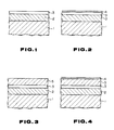
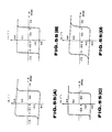
- Fig. 1 is a diagrammatic sectional view showing the most basic arrangement of the magneto-optical recording medium of the present invention.
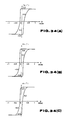
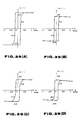
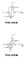
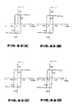
- Figs. 2 to 4 are diagrammatic sectional view showing modified exemplary constructions of the magneto-optical recording medium of the present invention wherein Fig. 2 shows an example of providing a metallic reflective layer on the recording layer, Fig. 3 an example of providing a dielectric layer on the recording layer and Fig. 4 an example of providing a dielectric layer and a metallic reflective layer on the recording layer in this sequence.
- Fig. 5 is diagram showing the thicknesses of the Co layer and the Pt layer in the Co-Pt type recording layer
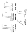
- Figs. 6A to 6C are characteristic diagrams showing typical magnetic Kerr rotation angle for typical Co-Pt type recording layer.
- Figs. 7A and 7B are characteristic diagrams showing magnetic Kerr loops of the Co-Pt type recording layer in which, for comparison with the Figs. 6A to 6C above.
- Fig. 8 is a characteristic diagram showing the coercivity of a typical Cp-Pt type recording layer.
- Fig. 9 shows a magnetic Kerr rotation angle a typical Co-Pt type recording layer.
- Fig. 10 shows the Curie point of a typical Co-Pt recording layer.
- Fig. 11 is a characteristic diagram showing the argon gas pressure dependency of the coercive force and the rectangular ratio of a recording layer obtained by stacking a 6 ⁇ Co layer and a 17.2 ⁇ Pt layer.
- Figs. 12A to 12C are characteristic diagrams showing magnetic Kerr loops for the same recording layer under typical argon gas pressures.
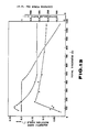
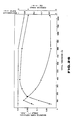
- Fig. 13 is a characteristic diagram showing the total thickness dependency of the magnetic Kerr rotation angle, rectangular ratio and the coercivity of the same recording layer.
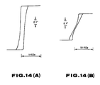
- Figs. 14A and 14B show magnetic Kerr loops showing the total thickness dependency of the magneto-optical properties of the recording layer.
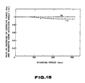
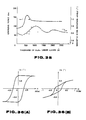
- Fig. 15 is a characteristic diagram showing the results of accelerated degradation tests for a recording layer formed by stacking a 6 ⁇ Co layer and a 11 ⁇ Pt layer, said layer being left under the high temperature high humidity environment.
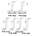
- Figs.16A and 16B are characteristic diagrams showing typical magnetic Kerr loops in the same accelerated degradation tests, wherein Fig. 16A shows the state before the layer is left under the above environment and Fig. 16B the state after 300 hours since the start of the accelerated degradation test.
- Figs. 17A to 17D are characteristic diagrams showing the magnetic Kerr loops for the case in which the same recording layer is allowed to stand in air or subjected to accelerated degradation tests under different conditions.
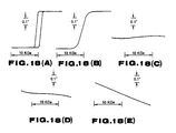
- Figs. 18A to 18E are characteristic curves for the case in which the typical recording layers containing the rare earth element Tb in place of Pt as a comparative example are allowed to stand in air or subjected to accelerated degradation tests.
- Fig. 19 is a diagram showing the thicknesses of the Co and Pd layers is the Co-Pd type recording layers.
- Figs. 20A and 20B are characteristic curves showing the magnetic Kerr loops of the typical Co-Pd type recording layer.
- Fig. 21 is a characteristic diagram showing the coercive force of a typical Co-Pt type recording layer.
- Fig. 22 is a characteristic diagram showing the magnetic Kerr rotation angle of the typical Co-Pt type recording layer.
- Fig. 23 is a characteristic diagram showing the Curie point of the typical Co-Pt type recording layer.
- Fig. 24 is a graph showing the argon gas pressure dependency of the coercive force and the rectangular ratio of the recording layer formed by stacking a 3.8 ⁇ Co layer and a 7.8 ⁇ Pd layer.
- Figs. 25A to 25C are characteristic curves showing the magnetic Kerr loops of the same recording layer under a typical argon gas pressure.
- Fig. 26 is a graph showing the total film dependency of the magnetic Kerr rotation angle, rectangular ratio and the coercive force of the same recording layer.
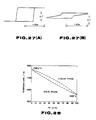
- Figs. 27A and 27B show magnetic Kerr loops showing the total thickness dependency of the magneto-optical characteristics of the recording layers.
- Fig. 28 is a phase diagram showing the Pt/Pd binary system.
- Figs. 29A to 29C are characteristic diagrams showing magnetic Kerr loops of a typical Co-Pt-Pd type recording layer.
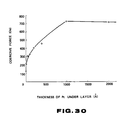
- Fig. 30 is a characteristic diagram showing the relation between the coercive force and the thickness of the Pt under layer in the magneto-optical recording medium having a Co-Pt type multi layered metal film as the recording layer.
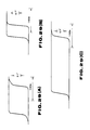
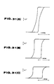
- Figs. 31A to 31C show magnetic Kerr loops showing the relation between the magneto-optical properties and the various thickness of the Pt under layer in the magneto-optical recording medium having the Co-Pt type multi layered metal film as the recording layer.
- Fig. 32 is a characteristic diagram showing the relation between the coercive force and the thickness of the Pd under layer in a magneto-optical recording medium having the Co-Pd type multi layered metal film as the recording layer.
- Figs. 33A to 33C show magnetic Kerr loops showing the relation between the magneto-optical characteristics and the thickness of the Pd under layer in an magneto-optical recording medium having a Co-Pd type multi layered metal film as the recording layer.
- Figs. 34A to 34C show magnetic Kerr loops showing the magneto-optical characteristics of the magneto-optical recording medium having a Co-Pt type multi layered film is formed on a glass substrate with the interposition of Si3N4 under layers of variable thicknesses.
- Fig. 35 is a characteristic diagram showing changes in the magnetic Kerr rotation angle and the coercive force caused with the thicknesses of the Si3N4 under layer in the same magneto-optical recording medium.
- Figs. 36A and 36B show magnetic Kerr loops showing changes in the magneto-optical characteristics caused with the presence or absence of the Si3N4 under layer in the same magneto-optical recording medium in the magneto-optical recording medium having a Co-Pt type multi layered film formed on a polycarbonate substrate.
- Fig. 37 is a characteristic diagram showing changes in the coercive force and the rectangular ratio with the thickness of the Si3N4 under layer in the same magneto-optical recording medium.
- Fig. 38 is a characteristic diagram showing changes in the magnetic Kerr rotation angle with the thickness of the Si3N4 under layer in the same magneto-optical recording medium.
- Fgis. 39A to 39D show magnetic Kerr loops showing magneto-optical properties of the magneto-optical recording medium having a Co-Pt type multi layered film is formed on a glass substrate through the interposition of the other nitride dielectric materials, wherein Figs. 39A to 39C show the case in which a 480 ⁇ thick ZrN under layer, a 40 ⁇ thick BN under layer and a 700 ⁇ AlN under layer are provided, respectively and Fig. 39D shows the case in which the under layer is not provided as a comparative example.
- Fig. 40 is a characteristic curve showing changes in the coercive force and the magnetic Kerr rotation angle with the thicknesses of a ZrN under layer in an magneto-optical recordeing medium having the ZrN under layer.
- Fig. 41 is a characteristic diagram showing changes in the coercive force with the thickness of the TiN under layer in the magneto-optical recording medium having the TiN under layer in place of the ZrN under layer.
- Figs. 42A and 42B show magnetic Kerr loops showing changes in magneto-optical properties caused by the presence or absence of the ZrN under layer in the magneto-optical recording medium having a Co-Pd type multi layered film on a glass substrate,
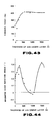
- Fig. 43 is a characteristic diagram showing changes in coercive force caused with the thickness of the ZrN under layer in the same magneto-optical recording medium
- Fig. 44 is a characteristic diagram showing changes in the magnetic Kerr rotation angle caused with the thickness of the ZrN under layer in the same magneto-optical recording medium
- Fig. 45 is a characteristic diagram showing changes in the magnetic Kerr rotation angle caused with the thickness of the TiN under layer in the above magneto-optical recording medium having the TiN under layer in place of the ZrN under layer.
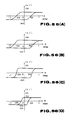
- Figs. 46A to 46D show magnetic Kerr loops showing magneto-optical properties of the magneto-optical recording medium haivng a Co-Pd type multi layered film formed on a glass substrate through the interpositon of a under layer of the other nitride dielectric materials, wherein Figs. 46A to 46C show the cases wherein a 1300 ⁇ Si3N4 under layer, a 300 ⁇ thick AlN under layer, a 1200 ⁇ BN under layer are provided, respectively and Fig. 46D shows the case wherein a under layer is not provided, as a comparative example.
- Fig. 47 is a characteristic diagram showing changes in the magnetic Kerr rotation angle with the thickness of the Si3N4 under layer in the same magneto-optical recording medium.
- Fig. 48 is a characteristic diagram showing changes in the magnetic Kerr rotation angle caused with the thickness of the AlN under layer in the same magneto-optical recording medium.
- Figs. 49A and 49B show magnetic Kerr curves showing changes in the magneto-optical properties caused by the presence or absence of the Ta2O5 under layer in the magneto-optical recording medium having the Co-Pt type artificial lattice film formed on a glass substrate, wherein Fig. 49A shows the case wherein a 200 ⁇ Ta2O5 under layer is provided and Fig. 49B that wherein the Ta2O5 is not provided as a comparative example.
- Fig. 50 is a characteristic diagram showing changes in the magneto-optical properties caused by the thickness of the Ta2O5 under layer in the magneto-optical recording medium having the Co-Pt type multi layered film formed on a glass substrate.
- Fig. 51 is a characteristic diagram showing changes in coercivity with different combination of the film thicknesses of the Ta2O5 under layer and a dielectric layer thereabove in an magneto-optical recording medium having a Co-Pt type multi layered film formed on a glass substrate.
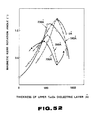
- Fig. 52 is a characteristic diagram showing changes in the magnetic Kerr rotation angle in the same magneto-optical recording medium.
- Figs. 53A to 53D show magnetic Kerr loops showing magneto-optical properties of the magneto-optical recording medium having a Co-Pt type multi layered film formed on a polycarbonate substrate through the interposition of Ta2O5 under layer of various thickness,
- Figs. 54 A and 54 B show magnetic Kerr loops showing changes in the magneto-optical characteristics caused by the presence or absence of the Ta2O5 under layer in the magneto-optical recording medium having a Co-Pd type multi layered film formed on a glass substrate,
- Figs. 55A to 55D show magnetic Kerr loops showing mageto-optical characteristics of the magneto-optical recording medium having a Co-Pd type multi layered film formed on a glass substrate with the interposition of a under layer of the other oxide dielectric materials, wherein Figs. 55A to 55C show the case wherein a 500 ⁇ thick SiO2 under layer, a 20 ⁇ thick Al2O3 under layer and a 60 ⁇ thick Al2O3 under layer are provided, respectively, and Fig. 55D shows the case wherein the under layer is not provided as a comparative example.
- Figs. 56A to 56C are characteristic diagrams showing a magneto-optical recording medium having a Co-Pd type multi layered film formed on a polycarbonate substrate through the interposition of Al2O3 under layers of various thicknesses.
- a multi layered film utilized as the recording layer in the magneto-optical recording medium of the present invention is a Co-Pt type multi layered film composed of Co layer and a Pt layer stacked alternately, a Co-Pd type artificial lattice film composed of Co layer and Pd layer stacked alternately, and a Co-Pt-Pd type multi layered film composed of Co layer, Pt layer and Pd stacked together.
- the multi layered film which is to be the recording layer, be of a total thickness ranging between 50 and 800 ⁇ , because the magneto-optical properties including the magnetic Kerr angle or the coercive force are lowered outside the above defined range.
- the Co layer be of a thickness ranging between 2 and 8 ⁇
- the Pt layer be of a thickness ranging between 3 and 40 ⁇
- the multi layered film be of the total thickness preferably ranging between 50 and 400 ⁇ , since the magneto-optical properties are optimum within these ranges.
- the magneto-optical properties are exhibited outside these ranges, for example, for the film thickness not larger than 800 ⁇ , the rectangular ratio is slightly lowered for the range above 400 ⁇ .
- the magneto-optical properties become optimum for the thickness of the Co layer ranging between 1 and 9 ⁇ , the thickness of the Pd layer ranging between 2 and 40 ⁇ and the total thickness ranging between 50 and 800 ⁇ .
- the above thickness ranges are set from the viewpoint of optimizing the magneto-optical properties.
- in-plane magnetization components are produced outside the above defined ranges to deteriorate the magneto-optical characteristics.
- the Co-Pt-Pd type artificial lattice film may be formed by stacking the Co layer and the Pt-Pd alloy layer alternately, or by stacking the layers in the order of Co-Pt-Co-Pd or Co-Pt-Pd-Co.
- the boundary surfaces of the metal surfaces making up each of multi layered films be smooth and flat, without the atoms of the different metals randomly existing together, so as to form a so-called super lattice structure
- the boundary surfaces may also have a so-called modulated structure (composition modulated structure) in which the composition is fluctuated with a certain periodicity as a whole despite certain perturbances in the boundary surfaces.
- the above multi layered film may also be formed by sputtering, vacuum deposition or molecular beam epitaxy (MBE).
- MBE molecular beam epitaxy
- each sputtering target need be provided for each of the component metals.
- the aforementioned three-component type magneto-optical recording medium it may be formed by a simultaneous binary sputtering employing a Co target and a Pd target on which is placed a Pt chip, a simultaneous ternary sputtering employing Co-, Pd and Pt targets, or a simultaneous quaternary sputtering in which the respective metal layers are stacked in the order of Co-Pd-Pt-Pd- ... using the Co, Pt and Pd targets.
- each evaporation source may be provided separately for each of the component metal, or a combined alloy evaporation source may be provided for a combination of Pt-Pd, or an evaporation source of the minor component metal may be superimposed on an evaporation source of the other metal.
- the aforementioned multi layered films may be admixed with a variety of elements as additive elements for increasing heat stability or lowering the Curie temperature.
- the additive elements when the additive elements are added to a Co layer of a multi layered film composed of the Co layer and a Pt layer stacked together, it is preferred that the Co layer be shown by the formula Co 100-x M x , wherein x stands for the amount of substitution in atomic percent and M stands for the additive element, and that the additive element be at least one of B, C, Al, Si, P, Ti, V, Fe, Ni, Cu, Ga, Ge, Zr, Nb, Mo, In, Sn, Sb, Gd, Tb, Dy and Ta.
- the lower limit for the amount of substitution x of the additive elements is 0.1 atomic percent. With the amount x less than this threshold value, the effect of lowering of the Curie pointis not exhibited.
- the upper limit of the amounts of substitution x of the elements range from 7 to 40 atomic percent depending on the kinds of the additive elements. With the amount x larger than these values, the magneto-optical properties are occasionally deteriorated.
- the aforementioned third element to the Pt layer to provide the composition of the Pt layer of Pt 100-x M x , wherein x stands for the amount of substitution in atomic percent and M stands for the additive element, it should not be the improvement in the magneto-optical properties or heat stability but in the adjustment of the Curie point that is primarily aimed at on such an occasion. It is because addition of the third element to the Pt layer results in increasing the Curie point and lowering the magnetic Kerr rotation angle, although not without exceptions.
- the unlimiatedly low Curie point however is not necessarily desired, from the standpoint of protecting the recording information, so that, when the Curie point of the recording layer is extremely low from the outset, it can be raised to a practical range by such means.
- the elements that can be added to the Pt layer include Cr, Mn, Co, Zn, Y, Rh, Ag, La, Nd, Sm, Eu, Ho, Hf, W, Ir, Au, Pb and Bi, in addition to the elements in common with the Co layer.
- the Pt layer may be replaced by Pd in any desired ratio.
- the Co layer is shown by Co 100-x M x , wherein x stands for the amount of substitution in atomic percent and M stands for the additive element and that the additive element be at least one of P, Ti, V, Ni, Ga, Ge, B, C, Al, Si, Fe, Cu, Zr, Nb, Mo, In, Sn, Sb, Ta and W.
- the grounds of limitation are similar to those for the aforementioned Co-Pt base artificial lattice film.
- the materials for the under layer are roughly classified into a metal and a dielectric material.
- the metal at least one of Cu, Rh, Pd, Ag, Ir, Pt and Au having a face-centered cubic structure (fcc structure) and W having a body-centered cubic structure (bcc structure).
- the kinds of the elements exhibiting the most outstanding effect will differ slightly depending on the kinds of the recording layer formed on the under layer such that the under layer of Pd, Ag, W, Pt and Au and the under layer of Pd, Ag, Pt and Au may be used for the Co-Pt type recording layer and for the Co-Pd type recording layer, respectively. These elements may be used alone or as a combination of two or more elements.
- the thickness of the under layer is preferably 5 to 5000 ⁇ and more preferably 5 to 500 ⁇ .
- the coercive force cannot be increased sufficiently with too small a thickness of the under layer, while the coercive force reaches saturation and hence a further favorable result cannot be expected with too large a thickness of the under layer.
- the under layer thickness is preferably 10 to 200 ⁇ when the signals are read from the substrate side, that is, the under layer side, and 200 to 2000 ⁇ when the signals are read from the multi layered film side.
- the dielectric materials include oxide type compounds, such as Al2O3, Ta2O5, MgO, SiO2, TiO2, Fe2O3, ZrO2 or Bi2O3, nitride type compounds such as ZrN, TiN, Si3N4, AlN, AlSiN, BN, TaN or NbN or oxide-nitride composite materials (so-called oxynitride compounds) when selected to an optimum thickness, this under layer has the effect of increasing the magnetic rotation Kerr angle by the interference effect (enhancement effect).
- oxide type compounds such as Al2O3, Ta2O5, MgO, SiO2, TiO2, Fe2O3, ZrO2 or Bi2O3, nitride type compounds such as ZrN, TiN, Si3N4, AlN, AlSiN, BN, TaN or NbN or oxide-nitride composite materials (so-called oxynitride compounds) when selected to an optimum thickness, this under layer has the effect of increasing the magnetic rotation Kerr angle by
- the substrate employed in the present invention may be formed of a material employed ordinarily as the substrate of the magneto-optical recording medium.
- a material employed ordinarily as the substrate of the magneto-optical recording medium may be mentioned glass, polycarbonate or polymethylmethacrylate (PMMA).
- the basic arrangement of the magneto-optical recording medium is shown in Fig. 1.
- a recording layer 3 is formed on the substrate 1 via under layer 2 of metal or dielectric material.
- a metal reflective layer 4 formed of Al, Au, Pt or Cu, for example, on the above recording layer 3.
- a second dielectric layer 5 may be additionally provided on the recording layer 3 for further improving magneto-optical properties, as shown in Fig. 3.
- the material of the dielectric layer 5 may be same as or different from that of the dielectric under layer 2.
- the metal reflecting layer 4 may be provided on the dielectric layer 5, as shown in Fig. 4.
- a metal under layer may further be interposed adjacent under the recording layer when the under layer 2 is formed of dielectric material.
- Any writing method for writing on the recording layer of the magneto-optical recording medium as described hereinabove may be employed in addition to the light beam, such as a needle-shaped magnetic head, heat pen or electron beam, or the condition that such means are capable of supplying an energy necessary for producing inverted magnetic domain.
- the present invention has opened the way to apply the film in the magneto-optical recording medium.
- the present invention also makes it possible to provide a under layer formed of at least one of Cu, Rh, Pd, Ag, W, Ir, Pt and Au in the magneto-optical recording medium, the recording layer of which is formed by the aforementioned superstructure or modulated structure thin metal film, for further improving the coercive force.
- the present invention provides a dielectric under layer between the substrate and the recording layer composed of a Co-Pt, Co-Pd or Co-Pd-Pt type multi layered films to increase the energy of the perpendicular magnetic anisotropy of the recording layer. This results in a sharper form of the write bits and an improved C/N ratio during the read-out operation. Moreover, an increase in the magnetic Kerr rotation angle may be expected by selecting the thickness of the base coat to an optimum value. Hence, it becomes possible to achieve a magneto-optical recording of high quality and density.
- the prospect is that the magneto-optical recording medium will be supplied in future more stably and economically.
- the magneto-optical recording medium is used as a storage medium of a magneto-optical memory, such as a so-called beam addressable file memory, in which signals are written by a light beam and read by a magnetic Kerr effect of a read light beam, respectively, it is possible to realize a memory device having an extremely high density, a larger C/N ratio and a higher reliability for an extended time.
- a magneto-optical memory such as a so-called beam addressable file memory
- the present embodiment is concerned with a Co-Pt type magneto-optical recording medium, the recording layer of which is a metal film obtained upon alternately stacking Co and Pt layers in the form of a multi layered structure.
- Co and Pt targets each 100 mm in diameter were placed in a chamber.
- a glass substrate was positioned facing to these targets and subjected to a simultaneous binary sputtering while being revolved at a predetermined speed of 6 to 60 rpm in an argon atmosphere of a prescribed gas pressure.
- a d.c. sputtering with a power of 0.2 to 1 A and 300 V was used for Co and a d.c. sputtering with a power of 0.2 to 1 A and 300 V or a RF sputtering with a power of 200 to 500 W was used for Pt.
- the Co and Pt layers were stacked alternately on the glass substrate to form a recording layer of a prescribed total thickness.
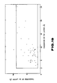
- Fig. 5 shows the thicknesses for the Co and Pt layers of each of the actually formed recording layers each having a total thickness of 100 ⁇ .
- the thickness of the Co layer in ⁇ is plotted on the ordinate and the thickness of the Pt layer in ⁇ is plotted on the abscissa.
- the thickness of 2.5 ⁇ and the thickness of 2.8 ⁇ correspond to the one atomic layer in Co and Pt, respectively.
- the dots in the figure represent the thickness of each atomic layer in each recording layer, whereas a frame in thick solid lines indicates the preferable range of the thickness for each layer.
- the small angle X-ray scattering has revealed that each recording layer has been turned into the multi layered metal film.
- Figs. 6A to 6C show the measured results of the magneto-optical effect for some of the recording layers included within the thick line frame in Fig. 5, from the side of the recording layer, using a polar Kerr measurement system at a wavelength of 780 nm.
- the recording layer are each formed to a total thickness of 100 A at an argon gas pressure of 5 mTorr.
- the magnetic Kerr rotation angle in degrees and the intensity of the external magnetic field in kOe are represented on the ordinate and the abscissa, respectively. It is seen from these figures that the rectangular ratio for each recording layer is equal to unity thus indicating that the recording layer has highly satisfactory magneto-optical characteristics.
- Fig. 10 shows the measured results of Curie point of several recording layers.
- the Curie point was found by a method in which the magneto-optical properties of the respective recording layers were measured in vacuum at the wavelength of 780 nm, then the magnetic field of 500 Oe was impressed and the temperature was increased simultaneously to find the temperature (°C) at which the magnetic Kerr rotation angle was equal to zero. It may be seen that the Curie point was distributed over a range of approximately 100 to 500 °C and that these recording layers can be used at a practical range of temperatures as the magneto-optical recording medium and can be set as desired in dependence upon the thickness of each atomic layer. Other species of elements may be optionally added to change the curie point.
- Fig. 11 shows the measured values plotted against the argon gas pressure.
- Figs. 12A to 12C show magnetic Kerr loops under typical argon gas pressures.
- Figs. 12A, 12B and 12C show the above loops for the argon gas pressures of 5, 11 and 25 mTorr, respectively. It is seen from Figs.
- the total thickness dependency of the magneto-optical properties of the same recording layer was then investigated.
- the argon gas pressure of 5 mtorr was need for sputtering.
- the results are shown in Fig. 13.
- the magnetic Kerr rotation angle in degrees, rectangular ratio or the coercive force in Oe is plotted on the ordinate
- the total thickness in ⁇ is plotted on the abscissa.
- the black circle plottings indicate the magnetic Kerr rotation angle
- the white circle plottings indicate the rectangular ratio
- the black triangular plotting indicate the coercive force.
- the total thickness for which the magnetic Kerr rotation angle presents a local maximum is generally in the range of from 80 to 150 ⁇ , with the rotation angle remaining substantially flat for the total thickness larger than 500 ⁇ .
- the value of the magnetic Kerr rotation angle shown in fig. 9 may be roughly said to be a local maximum value.
- Figs. 14A and 14B show the total thickness dependency of the magneto-optical properties of another test recording layer.
- Figs. 14A and 14B show the cases of the total thicknesses of 100 ⁇ and 500 ⁇ , respectively. It is seen from these figures that the magneto-optical properties of the recording layer of the total thickness of 100 ⁇ are superior to those of the recording layer of the total thickness of 500 ⁇ and thus in agreement with the above described tendency shown in Fig. 13.
- the larger magnetic Kerr rotation angle at the extremely small layer thickness is characteristic of the magneto-optical recording medium of the present invention and is highly convenient in elevating the transfer rate or the recording density.
- the corrosion resistance of the Co-Pt type recording layer was then investigated by accelerated degradation tests.
- the results are shown in Fig.
- the abscissa indicates the time the recording layer is allowed to stand in hours
- the white circle plottings indicate the coercive force
- the black circle plottings indicate the magnetic Kerr rotation angle
- Figs. 16A and 16B show typical magnetic Kerr loops in the present tests, wherein Fig. 16A shows the loop for the Co-Pt type recording layer before it is allowed to stand and Fig.
- figs. 17A, 17B, 17C and 17D show the magnetic Kerr curves of the respective recording layer before it is allowed to stand in air, after it is allowed to stand in air for one week, and after 5 hours and after 100 hours since the start of the accelarated degradation test under the hot and wet environment of the temperature of 80°C and the RH of 90%, respectively.
- the recording layer has a sufficiently high coercive force and a rectangular ratio close to unity and thus exhibits extremely stable magneto-optical properties, although the magnetic Kerr rotation angle is slightly lowered after 100 hours since the start of the accelerated degradation test.
- Figs. 18A to 18E show the magnetic Kerr loops of each recording layer before it is allowed to stand in air, after it is allowed to stand in air for one week, and after 2, 5 and 30 hours since the start of the accelerated degradation tests under the hot and wet environment of the temperature of 80 °C and the RH of 90%. It is seen from these figures that the magneto-optical properteis of the recording layer are significantly lowered after lapse of one week since it is allowed to stand in air and are almost completely lost after two hours since the start of the accelerated test.
- the present embodiment is concerned with a Co-Pd type magneto-optical recording medium, the recording layer of which is a metal film obtained upon alternately stacking Co and Pd layers in the form of a multi layered structure.
- Co and Pd targets each 100 mm in diameter, were placed in a chamber.
- a glass substrate was positioned facing to these targets and subjected to a simultaneous binary sputtering while being revolved at a predetermined speed of 6 to 60 rpm in an argon atmosphere maintained at a prescribed gas pressure.
- a d.c. sputtering with a power of 0.2 to 1 A and 300 V was used for Co and a d.c. sputtering with a power of 0.2 to 1 A and 300 V or a RF sputtering with a power 200 to 500 W was used for Pd.
- the Co and Pd layers were stacked alternately on the glass substrate to form a recording layer or a prescribed total thickness.
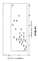
- Fig. 19 shows the thicknesses for the Co and Pd layers of each of the actually formed recording layers each having a total thickness of 100 ⁇ .
- the thickness of the Co layer in ⁇ is plotted on the ordinate and that of the Pd layer in ⁇ is plotted on the abscissa.
- the thickness of 2.5 ⁇ and 2.8 ⁇ correspond to the one atomic layer in Co and Pd, respectively.
- the dots in the figure represent the thickness of each atomic layer in each recording layer, whereas a frame in thick solid lines indicates the preferable range of thickness for each layer.
- the small angle X-ray diffraction has revealed that each recording layer has been turned into the multi layered metal film.
- Figs. 20A and 20B show the measured results, as measured from the side of the recording layer, of the magneto-optical effect for some of the recording layers included within the thick line frame in Fig. 5, using a polar Kerr measurement system at a wavelength of 780 nm.
- Each of the recording layers is formed to a total thickness of 150 ⁇ at the argon gas pressure of 11 mTorr.
- the rectangular ratio of each recording layer is equal to unity, meaning that the recording layer has superior magneto-optical properties.
- Figs. 21 and 22 show the coercive force as found from the magnetic Kerr loop and the magnetic Kerr rotation angle, respectively. It is seen from these figures that the coercive force amounts to several tens to 200 Oe and the magnetic Kerr rotation angle amounts to a larger value of 0.2 degree at the maximum.
- Fig. 23 shows the measured results of the Curie point of several recording layers.
- the Curie point was distributed over a range of about 100° to 500°C and that these recording layers can be used at a practical range of temperatures as the magneto-optical recording medium and can be set as desired in dependence upon the thickness of each atomic layer.
- Other species of the elements may be optionally added to change the Curie point.
- Fig. 24 shows the values of these parameters plotted against the argon gas pressure. In the figure, the black and white circle plottings indicate the coercive force and the rectangular ratio, respectively.
- 21A to 21C illustrate magnetic Kerr curve under typical argon gas pressures of 5, 11 and 25 mTorr, respectively. Referring to Figs. 24 and 25A to 25C, the coercive force is increased with increase in the argon gas pressure while the rectangular ratio is maintained so as to be equal to unity.
- Fig. 26 The results are shown in Fig. 26.
- the magnetic Kerr rotation angle in (°), rectangular ratio or the coercive force in Oe were plotted on the ordinate and the total thickness in ⁇ was plotted on the abscissa.
- the black and white circle plottings indicate the magnetic Kerr rotation angle and the rectangular ratio, respectively, while the black triangle plottings indicate the coercive force.
- the rectangular ratio remains satisfactory up to about 800 ⁇ and is gradually decreased beyond 800 ⁇ .
- Both the coercive force and the magnetic Kerr rotation angle are changed in a manner of presenting local maximum values, so that, in consideration of various characteristics, the optimum total thickness may be said to lie in the vicinity of 150 ⁇ . It is for this reason that the various test data are prepared in the present embodiment for the total thickness of 150 ⁇ .
- Figs. 27A and 27B The total thickness dependency of the magneto-optical properties of another test recording layer was checked from the magnetic Kerr loop. The results are shown in Figs. 27A and 27B.
- Figs. 27A and 27B show the cases wherein the total thicknesses of 200 ⁇ and 500 ⁇ , respectively. It is seen from these figures that the recording layer with the total thickness of 200 ⁇ is superior to that with the total thickness of 500 ⁇ .
- the present embodiment is concerned with a Co-Pt-Pd type magneto-optical recording medium, the recording layer of which is the ternary metal film composed of Co, Pt and Pd.
- a simultaneous binary sputtering may be resorted to with the use of a Pt-Pd alloy target and a Co target.
- a Pd chip may simply be placed on a Pt target, or conversely, a Pt chip may be placed on a Pd target, in place of using a Pt-Pd alloy target.
- the respective metal layers may be stacked by simultaneous ternary sputtering, with the use of separate targets for the three components.
- a stacked structure such as Co-Pd-Pt-Pd Vietnamese may be produced by simultaneous quaternary sputtering.
- a d.c. sputtering with a power of 0.2 to 1 A and 300 V is employed for Co, whereas a d.c. sputtering with a power of 0.2 to 1 A and 300 V or an RF sputtering with a power of 200 to 500W is used for the Pt-Pd alloy.
- Figs. 29A to 29C illustrate magnetic Kerr curves of recording layers prepared in the above described manner, that is, a recording layer obtained upon alternately stacking a 2.5 ⁇ , thick Co layer and a 7 ⁇ thick Pt-Pd alloy layer by simultaneous binary sputtering to a total thickness of 100 ⁇ , a recording layer obtained upon stacking a 2.5 ⁇ Co layer, a 2.8 ⁇ Pt layer and a 2.8 ⁇ Pd layer by simultaneous ternary sputtering to a total thickness of 100 ⁇ , and a recording layer obtained upon stacking a 2.5 ⁇ Co layer, a 2.8 ⁇ Pd layer, a 2.8 A Pt layer and a 2.8 ⁇ , Pd layer in this order by simultaneous quaternary sputtering to a total thickness of 100 ⁇ .
- the coercive force is slightly low (about 200 Oe) but the magnetic Kerr rotation angle is larger (about 5°).
- the coercive force is higher (over about 500 Oe) but the magnetic Kerr rotation angle is smaller (about 0.25 minute).
- the magneto-optical properties can be significantly controlled by using a ternary system recording layer and changing the stacking system for the respective metal layers.
- the present embodiment is concerned with a magneto-optical recording medium, the recording layer of which is formed by alternately stacking Co and Pt layers by simultaneous binary magnetron sputtering, with the use tentatively of various elements of the base coat or layer.
- a target of an element for the base coat material which is 100 mm in diameter, was placed in a chamber of a magnetron sputtering device, along with Co and Pt targets.
- a water-cooled glass substrate was placed on a rotary base plate for facing to these targets.
- the water-cooled glass substrate was then placed facing to the target of the element of the under layer material for forming the metal under layer.
- the elements Cu, Rh, Pd, Ag, W, Ir, Pt and Au were employed. Besides these elements, studies were conducted on using the elements Ti, Al, Si, V, Cr, Mn, Ge, Y, Zr, Nb, Mn, Ge, Y, Zr, Nb, Mo, Sb, Gd and Ta.
- a recording layer was then formed on the metal under layer by a simultaneous binary magnetron sputtering in the argon gas atmosphere at a gas pressure of 5 mTorr.
- the above described system makes it possible to determine the period of the multi layered as desired by changing the rotation speed of the rotary base plate mounting the water-cooled base plate or the power applied to each target.
- a sample devoid of the metal under layer that is, a sample in which the recording layer was directly formed on the glass substrate, was also prepared.
- the coercive force of the samples having various base coats thus prepared is shown in Table 1. Bars entered in the column of the coercive force in the table indicate that the sample shows no properties of perpendicular magnetization.
- the sample devoid of the metal under layer has a coercive force of 125 Oe.
- the elements capable of increasing the coercive force beyond this value when used as the metal under layer include Pd, Ag, W, Pt, Ti and Gd, of which Ti and Gd show only poor results.
- Pd, Ag, W, Pt, Ti and Gd of which Ti and Gd show only poor results.
- Cu, Rh, Ir and Au are capable of increasing the coercive force.
- Pd, Ag, W, Pt and Au are most preferred in this respect.
- Figs. 31A to 31C show the properties of a sample having no under layer, a sample having a 50 ⁇ thick Pt under layer and a sample having a 200 ⁇ Pt under layer, respectively.
- the ordinate and the abscissa in the figure denote the magnetic Kerr rotation angle in ⁇ k (°) by a relative scale and the intensity of the external magnetic field in kOe, respectively.
- the rectangular ratio is improved by the provision of the under layer.
- the present embodiment is concerned with a magneto-optical recording medium, the recording layer of which is a thin metal film obtained by alternately stacking Co and Pd layers by simultaneous binary sputtering, wherein studies are made of various element to be used as the under layer material.
- a target of an element for the metal under layer material which is 100 mm in diameter, was placed in a chamber of a magnetron sputtering device, along with Co and Pt targets.
- a water-cooled glass substrate was placed on a rotating base plate for facing to these targets.
- a 400 ⁇ thick metal under layer was formed on the water-cooled glass substrate.
- the elements same as those of the fourth embodiment were used.
- the simultaneous binary magnetron sputtering was then performed in an argon atmosphere of a gas pressure equal to 11 mTorr to form a recording layer on the metal under layer.
- a sample devoid of the metal under layer that is, a sample in which the recording layer was directly formed on the glass substrate, was also prepared.
- the sample devoid of the metal under layer has a coercive force of 825 Oe.
- the elements capable of increasing the coercive force beyond this value when used as the under layer include Pd, Ag and Pt.
- Pd, Ag and Pt are capable of increasing the coercive force.
- Cu, Rh, Ir and Au are capable of increasing the coercive force.
- Pd, Ag, Pt and Au are most preferred, in this respect.
- the relation between the coercive force and the under layer thickness was checked.
- the results are shown in Fig. 32, wherein the ordinate and the abscissa denote the coercive force in Oe and the under layer thickness in ⁇ , respectively.
- the coercive force starts to be increased at a small thickness of 10 ⁇ , reaching a value of 3750 Oe which is about four times at 400 ⁇ .
- Figs. 33A to 33C show the properties of a sample having no under layer, a sample having a 50 ⁇ thick Pt under layer and a sample having a 200 ⁇ Pt under layer, respectively.
- the ordinate and the abscissa in the figure denote the magnetic Kerr rotation angle in ⁇ k (°) by a relative scale and the intensity of the external magnetic field in kOe, respectively.
- the coercive force may be improved by providing the metal under layer.
- the present embodiment is concerned with a magneto-optical recording medium in which a Co-Pt type multi layered film is formed on the glass substrate with the interposition of a Si3N4 dielectric under layer.
- a sintered Si3N4 target 100 mm in diameter, was placed in a chamber, and a glass substrate was placed on a base fitted with a water-cooling device and provided facing to the target.
- the reactional sputtering was then performed in an argon gas atmosphere containing a 1% nitrogen gas at a gas pressure of 2.5 mTorr for depositing Si3N4 under layers to various thicknesses.
- Co and Pt targets each 100 mm diameter, were placed in the same chamber.
- a d.c. sputtering with a making power of 0.40 A and 300 W and a RF sputtering with a making power of 360W were used for Co and Pt, respectively, and the rotation speed of the base was set to 16 r.p.m. to form a Co-Pt type multi layered film having a total thickness of 100 ⁇ .
- the period of the produced multi layered film was found from the peak angle in the X-ray small angle scattering.
- the magneto-optical properteis at 780 mm of the so-produced magneto-optical recording medium samples were measured from the side of the glass substrate by a Kerr loop measurement system.
- the results are shown in Figs. 34A and 34B for the Si3N4 under layer thicknesses of 550 ⁇ and 1750 ⁇ , respectively.
- the ordinate and the abscissa denote the magnetic Kerr rotation angle ⁇ k in (°) and the intensity of the external magnetic field in kOe, respectively. It is apparent from comparison of these figures that both the coercive force and the rectangular ratio are improved when the recording medium is provided with the Si3N4 under layer than when the recording medium is not provided with the under layer.
- Fig. 35 wherein changes in the coercive force and the magnetic Kerr rotation angle caused by the thickness of the Si3N4 under layer are illustrated.
- the ordinate and the abscissa indicate the coercive force in Oe and the under layer thickness in ⁇ , respectively, whereas black and white circle plottings denote the coercive force and the magnetic Kerr rotation angle, respectively. It is seen from this figure that the coercive force becomes locally maximum at the under layer thickness of 550 ⁇ corresponding to the case shown in Fig.
- the magnetic Kerr rotation angle is changed periodically with respect to the Si3N4 under layer thickness and a difference of the order of 25% exists between the minimum and the maximum values within the measured range, thus indicating that the magnetic Kerr rotation angle may be increased by optimizing the base coat thickness.
- the present embodiment is concerned with a magneto-optical recording medium similarly including a Si3N4 under layer and a Co-Pt type multi layered film, with the aforementioned glass substrate being replaced by a polycarbonate substrate.
- the magneto-optical recording medium was prepared in the following manner.
- a reactional sputtering in an argon gas atmosphere containing a 1% nitrogen gas, maintained at a gas pressure of 2.5 mTorr a 700 ⁇ thick Si3N4 under layer was deposited on the polycarbonate substrate.
- a Co layer was formed on the substrate by d.c.
- the magneto-optical recording medium devoid of the Si3N4 under layer was similarly prepared.
- Figs. 36A and 36B show magnetic Kerr loops when the magneto-optical properties of these samples of the magneto-optical recording medium are measured from the substrate side.
- the recording medium is provided and not provided with the Si3N4 under layer, respectively. It is seen from these figures that the perpendicular magnetic properties are not exhibited when the under layer is not formed on the polycarbonate substrate, and that these properties are exhibited only when the under layer is formed on the substrate.
- Fig. 37 shows changes in the coercive force and magnetic Kerr rotation angle caused with the Si3N4 under layer thickness.
- the ordinate and the abscissa denote the coercive force in Oe or rectangular ratio and the Si3N4 under layer thickness in A
- the black and white circle plottings denote the coercive force and the rectangular ratio, respectively. It is seen from this figure that the coercive force becomes locally maximum in the vicinity of the under layer thickness of 700 ⁇ in correspondence with the case shown in Fig. 36A, and that the rectangular ratio may assume a substantially complete value for the similar under layer thickness region, and a desirable value close to unity for a under layer thickness region larger than 700 ⁇ .
- Fig. 38 shows changes in the magnetic Kerr rotation angle caused by the Si3N4 under layer thickness.
- the ordinate and the abscissa denote the magnetic Kerr rotation angle in (°) and the thickness of the Si3N4 under layer in ⁇ , respectively.
- Periodic changes in the magnetic Kerr rotation angle with respect to the under layer thickness may be observed herein as in the case shown in Fig. 35.
- the above described sixth and seventh embodiments are concerned with the magneto-optical recording medium having the Si3N4 under layer.
- the present embodiment is concerned with a magneto-optical recoding medium wherein a Co-Pt type multi layered film is formed on a glass substrate with the interposition of a dielectric under layer formed of nitride dielectric materials.
- the nitride dielectric materials employed in the present embodiment are ZrN, BN, AlN and TiN.
- the magneto-optical recording medium employing these materials were prepared in the following manner. By a reactional sputtering in an argon gas atmosphere containing a 1% nitrogen gas, at a gas pressure of 2.5 mTorr, a ZrN, BN or an AlN under layer was deposited on each of the glass substrates to various thicknesses. Then a Co layer was formed on the substrates by d.c.
- the magneto-optical recording medium devoid of the dielectric under layer was similarly produced.
- the magnetic Kerr loops when the magneto-optical properties of these magneto-optical recording medium samples were measured from the substrate side, are shown in Figs. 39A, 39B, 39C and 39D for the cases in which a 480 ⁇ ZrN under layer, a 400 ⁇ BN under layer and a 700 ⁇ AlN under layer are provided, and no under layer is provided, respectively.
- the coercive force and the magnetic Kerr rotation angle when the under layer is not provided, amount to 112 Oe and 0.61°, respectively.
- the coercive force, rectangular ratio and the magnetic Kerr rotation angle are improved by providing the under layer, above all, by providing the ZrN under layer.
- the Co-Pt multi layered films are unexceptionally employed as the recording layer.
- the present Embodiment is concerned with a magneto-optical recording medium in which a Co-Pd type multi layered film is formed on the glass substrate with the interposition of a ZnN under layer.
- This magneto-optical recording medium was prepared in the following manner.
- ZrN under layers were formed to various thicknesses on the glass substrates.
- Co and Pd layers were alternately stacked on the glass substrate by d.c. sputtering with a power of 0.35 A and 300 V for Co and an RF sputtering with a power of 380 W for Pd, under an argon atmosphere maintained at the gas pressure of 11 mTorr, so as to form a Co-Pd type multi layered film to a total thickness of 100 ⁇ to produce a magneto-optical recording medium.
- a magneto-optical recording medium devoid of the ZrN under layer was also produced.
- the magnetic Kerr loops when the magneto-optical properties of these magneto-optical recording media are measured from the substrate side are shown in Figs. 42A and 42B for the cases in which a 200 ⁇ thick ZrN under layer is provided and in which a ZrN under layer is not provided, respectively. It is seen from comparison of these figures that the coercive force and the magnetic Kerr rotation angle are 225 Oe and 0.17°, respectively, when the ZrN under layer is not provided, whereas both the coercive force and the magnetic Kerr rotation angle as well as the rectangular ratio are improved by providing the ZrN under layer.
- Fig. 43 shows changes in the coercive force with ZrN under layer thicknesses. As may be seen from this figure, the coercive force reaches a saturation in the vicinity of the base coat thickness of 500 ⁇ and the saturation value is about twice the value for the case of not providing the ZrN base coat.
- Fig. 44 shows changes in the magnetic Kerr rotation angle with the ZrN under layer thicknesses. It is seen from this figure that the magnetic Kerr rotation angle is periodically changed with respect to the ZrN under layer thickness with the enhancement effect being more than twice at the peak value that attained when not providing the ZrN under layer. However, an optimum under layer thickness need be investigated for practical applications, since the magnetic Kerr rotation angle may assume a negative value after zero crossing so far as a certain under layer region (so-called inversion phenomenon of the magnetic Kerr loops) is concerned.
- the ninth embodiment is concerned with the magneto-optical recording medium having a ZrN under layer.
- the present embodiment is concerned with a magneto-optical recording medium in which a Co-Pd type multi layered film is formed on the glass substrate through the interposition of a under layer of a nitride dielectric material.
- the nitride dielectric materials employed in the present embodiment are Si3N4, AlN and BN.
- the magneto-optical recording mediums employing these materials were prepared in the following manner. First, in accordance with the procedure shown in the above described fourth embodiment, Si3N4, AlN or BN under layers were deposited to various thicknesses on glass substrates. Then, using an argon atmosphere at the gas pressure of 11 mTorr, a d.c.
- sputtering with a power of 0.35 A and 300 V and a RF sputtering with a power of 360 W were performed for Co and Pd targets, respectively, for sequentially stacking Co and Pd layers on each of the glass substrates to form a Co-Pd type multi layered film with a total thickness of 100 ⁇ to produce a magneto-optical recording medium.
- a magneto-optical recording medium devoid of the under layer was also produced.
- the magnetic Kerr loops when the magneto-optical properties of the magneto-optical recording medium samples are measured from the substrate side, are shown in Figs. 46A to 46D, for the cases in which a 1300 ⁇ Si3N4 under layer, a 300 ⁇ AlN under layer and a 1200 ⁇ BN under layer are provided and no under layer is provided, respectively.
- the coercive force and the magnetic Kerr rotation angle for the case of not providing the under layer amount to 675 Oe and 0.195°, respectively.
- the coercive force, rectangular ratio and the magnetic Kerr rotation angle are improved when using the under layer, above all, the Si3N4 under layer.
- Figs. 47 and 48 show changes in the magnetic Kerr rotation angle caused by the Si3N4 under layer thickness and those caused by the AlN under layer thickness, respectively. It is apparent from these figures that an optimum under layer thickness exists for each of the under layers.
- the enhancement effect at the peak value amounts to twice or more that attained when not providing the under layer.
- the above described sixth to tenth embodiments refer to the cases in which a nitride dielectric material is used as the under layer.
- An example of using the oxide dielectric material as the under layer will be explained hereinbelow.
- the present embodiment is concerned with a magneto-optical recording medium wherein a Co-Pt type multi layered film is formed on a glass substrate with the interposition of a Ta2O5 under layer.
- the magneto-optical recording medium was prepared in the following manner. First, using a Ta2O5 target, 100 mm across, an RF sputtering was carried out in an argon atmosphere with a gas pressure of 4 mTorr and with a making power of 300W, for depositing a 1600 ⁇ thick Ta2O5 under layer on a glass substrate. Then, in a 4 mTorr argon atmosphere and rotation speed of the rotary base plate of 16 r.p.m., Co and Pt layers were sequentially formed on the glass substrate by a d.c.
- the magnetic Kerr loops when the magneto-optical properties of the respective samples were measured from the substrate side, are shown in Figs. 49A and 49B, for the cases in which a 1600 ⁇ Ta2O5 under layer is provided and no Ta2O5 film is provided, respectively.
- the magnetic Kerr rotation angle and the coercive force for the case of not providing the Ta2O5 under layer amount to 0.84° and 187.5 Oe, respectively. These parameters are improved to 0.98° and 225 Oe, respectively, by providing the Ta2O5 under layer.
- Fig. 50 wherein the ordinate and the abscissa denote the magnetic Kerr rotation angle ⁇ k (°) as measured from the substrate side or the coercive force in Oe and the Ta2O5 under layer thickness in ⁇ , respectively, and wherein white circle and white square plottings indicate the magnetic Kerr rotation angle ⁇ k and the coercive force, respectively.
- a point F denotes the value of ⁇ k for the magnetic Kerr rotation angle of the magneto-optical recording medium devoid of the Ta2O5 under layer, when measured from the side of the recording layer. It is seen from the figure that, even in the absence of the Ta2O5 under layer, the magnetic Kerr rotation angle ⁇ k as measured from the substrate side is larger than the magnetic Kerr rotation angle ⁇ k as measured from the side of the recording layer, as a result of the enhancement effect combined with the refractivity index of the glass substrate.
- the magnetic Kerr rotation angle ⁇ k as measured from the substrate side becomes locally maximum in the vicinity of the Ta2O5 under layer thickness of ca. 800 ⁇ .
- the coercive force is increased up to about 600 ⁇ of the Ta2O5 under layer thickness more acutely than when the under layer is not provided, however, the coercive force is decreased for larger under layer thicknesses.
- the rectangular shape of the magnetic Kerr loop has been evaluated on the basis of rectangularity.
- a value ⁇ H thought to be a measure of the anisotropic energy.
- the values ⁇ H in Figs. 49A and 49B are equal to 540 Oe.
- the present embodiment is concerned with a magneto-optical recording medium wherein an upper Ta2O5 dielectric layer is formed on the Co-Pt type multi layered film of the magneto-optical recording medium prepared in the eleventh embodiment.
- the upper Ta2O5 dielectric layer was formed by a procedure similar to that for forming the Ta2O5 under layer, and finally a Pt reflective film was formed.
- Fig. 51 shows the results of investigations into changes in the coercive force with various thicknesses of the Ta2O5 under layer and the upper Ta2O5 dielectric layer of the magneto-optical recording medium.
- the ordinate and the abscissa stand for the coercive force in Oe and the thickness of the upper Ta2O5 dielectric layer in ⁇
- the curves in the figure stand for different thicknesses of the Ta2O5 under layer
- white circle plotting denote the case of not providing the Ta2O5 under layer
- the rectangle, rhombus, white triangle and black triangle plottings denote the cases of the Ta2O5 under layer thicknesses of 180 ⁇ , 230 ⁇ , 350 ⁇ and 700 ⁇ , respectively.
- the ordinate and the abscissa represent the magnetic Kerr rotation angle ⁇ k (°) and the thickness of the upper Ta2O5 dielectric layer in ⁇ .
- the meanings of the respective curves are the same as in the case of Fig. 51.
- the coercive force is changed multifariously by different combination of the thickness of the Ta2O5 under layer and the upper Ta2O5 dielectric layer.
- the coercive force tends to be lowered in its entirety when only the upper Ta2O5 dielectric layer is provided with omission of the Ta2O5 under layer.
- the coercive force is seen to be increased when the thickness of the upper Ta2O5 dielectric layer becomes equal to or larger than that of the Ta2O5 under layer.
- the coercive force is increased acutely to 410 Oe, 570 Oe and 700 Oe for the Ta2O5 under layer thickness of 180 ⁇ , 230 ⁇ and 350 ⁇ , respectively.
- the magnetic Kerr rotation angle ⁇ k is also changed in dependence upon the thickness of Ta2O5 under layer.
- the so-called enhancement effect presents itself for both of these parameters up to a predetermined thickness of the upper Ta2O5 dielectric layer.
- the present embodiment is concerned with a magneto-optical recording medium wherein a polycarbonate substrate is employed in place of the glass substrate in the eleventh embodiment.
- the magneto-optical recording medium was produced in the following manner. First, Ta2O5 under layers were formed to various thicknesses by a procedure similar to that of the eleventh embodiment except that a polycarbonate substrate was used as the substrate. Then, Co and Pt layers were sequentially stacked on the substrate by a d.c. sputtering with a power of 0.40 A and 300 V and an RF sputtering with a power of 450 W, respectively, under a argon atmosphere at the gas pressure of 4 mTorr and at the substrate rotation of 16 r.p.m., so as to form a Co-Pt type multi layered film having a total thickness of 100 ⁇ to form a magneto-optical recording medium. For comparison, a magneto-optical recording medium devoid of the Ta2O5 under layer was also prepared.
- the magnetic Kerr loops when the magneto-optical properties of these magneto-optical recording medium are measured from the substrate side are shown in Figs. 53A to 53D, for the cases of providing Ta2O5 under layers with thicknesses of 30, 130 and 220 ⁇ and not providing the Ta2O5 under layer, respectively.
- the coercive force when the Ta2O5 under layer is not provided is 180 Oe.
- the coercive force of the magneto-optical film is increased with increase in the thickness of the Ta2O5 under layer, such that the coercive force is equal to 230, 250 and 270 Oe when the Ta2O5 under layers with thicknesses of 30, 130 and 220 ⁇ are used, respectively. This is possibly ascribable to the increase in the energy of the perpendicular magnetic anisotropy caused by the provision of the base coat.
- the present embodiment is concerned with a magneto-optical recording medium wherein the Co-Pd multi layered film is used in place of the Co-Pt type multi layered film.
- This magneto-optical recording medium was produced in the following manner. First, a 1000 ⁇ Ta2O5 under layer was formed on the glass substrate by using a procedure similar to that of the eleventh embodiment. Then, Co and Pt layers were sequentially stacked on the glass substrate by a d.c. sputtering with a power of 0.35 A and 300 V and by an RF sputtering with a power of 330 W, respectively, in an argon atmosphere at the gas pressure of 12 mTorr and at the 16 r.p.m. of the rotating base plate, so as to form a Co-Pd type multi layered film to a total thickness of 100 ⁇ to produce a magneto-optical recording medium. For comparison, a magneto-optical recording medium devoid of the Ta2O5 under layer was also produced.
- the magnetic Kerr loops when the magneto-optical properties of these magneto-optical recording medium samples were measured from the substrate side, are shown in Figs. 54A and 54B, for the case of providing the Ta2O5 under layer and the case of not providing the Ta2O5 under layer, respectively.
- the magnetic Kerr rotation angle, coercive force and ⁇ H when the Ta2O5 under layer is provided are equal to 0.21°, 570 Oe and about 75 Oe.
- the coercive force is decreased slightly, however, ⁇ H is reduced to about one-fifth, in the latter case, thus indicating that the recording medium exhibits superior perpendicular magnetic anisotropy.
- the above described eleventh to fourteenth embodiments refer to the magneto-optical recording medium including the Ta2O5 under layer.
- the present embodiment is concerned with a magneto-optical recording medium wherein a Co-Pd type multi layered film is formed on the glass substrate with the interposition of an under layer of a further oxide dielectric material.
- the oxide dielectric materials employed in the present embodiment are SiO2 and Al2O3.
- the magneto-optical recording medium employing these oxide materials was prepared in the following manner.
- SiO2 under layers and Al2O3 under layers were deposited to various thicknesses on glass substrates by sputtering at the gas pressure of 4 mTorr in an argon gas atmosphere.
- Co and Pd layers were sequentially stacked on these glass substrates by a d.c. sputtering with a making power of 0.35 A and 300 V and by an RF sputtering with a making power of 330 W, respectively, under a argon gas atmosphere with the gas pressure of 4 mTorr, so as to form a Co-Pd type multi layered film to a total thickness of 100 ⁇ to produce a magneto-optical recording medium.
- the magneto-optical recording medium devoid of the under layer was also prepared.
- the magnetic Kerr loops when the magneto-optical properties of these magneto-optical recording media are measured from the substrate side are shown in Figs. 55A to 55D, for the cases of providing a 500 ⁇ SiO2 under layer, a 20 ⁇ Al2O3 under layer and a 60 ⁇ Al2O3 under layer and the case of not providing the under layer, respectively.
- the magnetic Kerr rotation angle and the coercive force when the under layer is not provided are equal to 0.32° and 110 Oe, respectively.
- the magnetic Kerr rotation angle and the coercive force, when the 500 ⁇ SiO2 under layer is provided, are equal to 0.38° and 1000 Oe, respectively.
- the coercive force is slightly lowered, the magnetic Kerr rotation angle and the rectangular ratio are improved. Magnetic Kerr rotation angle and the rectangular ratio are also seen to be improved by providing the Al2O3 under layer.
- the present embodiment is concerned with a magneto-optical recording medium wherein a polycarbonate substrate is employed in place of the glass substrate in the above described fifteenth embodiment and wherein a Co-Pd type multi layered film is formed with the interposition of the Al2O3 under layer.
- This magneto-optical recording medium was produced in the following manner.
- Al2O3 under layers were deposited to various thicknesses on the polycarbonate substrates by sputtering in an argon gas atmosphere at a gas pressure of 4 mTorr.
- Co-Pd multi layered films were formed each to a total thickness of 100 ⁇ , by a procedure similar to that employed in the above described fifteenth embodiment, to produce magneto-optical recording media.
- the magnetic Kerr loops when the magneto-optical properties of these respective magneto-optical recording media are measured from the substrate side, are shown in Figs. 56A to 57D, for the cases of providing a 20 ⁇ Al2O3 under layer, a 100 ⁇ Al2O3 under layer and a 150 ⁇ Al2O3 under layer and not providing the Al2O3 under layer, respectively. It is seen from these figures that the coercive force is increased on providing the Al2O3 under layer, even with the under layer thickness as small as 20 ⁇ , and that the rectangular properties are also improved with increase in the under layer thickness.
- the present invention is not limited to these embodiments.
- the effect of the dielectric under layer may be attained in the case of a magneto-optical recording medium, the recording layer of which is formed by a Co-Pd-Pt type multi layered film, in which Co, Pd and Pt layers or Co layer and Pd-Pt alloy layers are stacked with proper sequence and thicknesses.
Claims (14)
- Support d'enregistrement magnéto-optique, comprenant un substrat (1) et une couche (3) d'enregistrement magnéto-optique formée sur le substrat, caractérisé en ce que :
la couche d'enregistrement magnéto-optique a une structure multicouche formée par empilement en alternance de couches formées de Co et de couches formées de Pt et/ou Pd, la couche d'enregistrement magnéto-optique ayant une épaisseur totale comprise entre 5 nm (50 Å) et 80 nm (800 Å). - Support d'enregistrement magnéto-optique selon la revendication 1, dans lequel les couches formées de Pt et/ou Pd sont formées de Pt.
- Support d'enregistrement magnéto-optique selon la revendication 2, dans lequel chacune des couches formées de Co a une épaisseur comprise entre 0,2 nm (2 Å) et 0,8 nm (8 Å), et chacune des couches formées de Pt a une épaisseur comprise entre 0,3 nm (3 Å) et 4 nm (40 Å).
- Support d'enregistrement magnéto-optique selon la revendication 1, dans lequel les couches formées de Pt et/ou Pd sont formées de Pd.
- Support d'enregistrement magnéto-optique selon la revendication 4, dans lequel chacune des couches formées de Co a une épaisseur comprise entre 0,1 nm (1 Å) et 0,9 nm (9 Å), et chacune des couches formées de Pd a une épaisseur comprise entre 0,2 nm (2 Å) et 4 nm (40 Å).
- Support d'enregistrement magnéto-optique selon la revendication 3, dans lequel la couche d'enregistrement magnéto-optique a une épaisseur totale comprise entre 5 nm (50 Å) et 40 nm (400 Å).
- Support d'enregistrement magnéto-optique selon la revendication 1, comprenant une sous-couche (2) formée entre le substrat et la couche d'enregistrement, la sous-couche étant formée d'au moins un élément métallique choisi dans le groupe qui comprend Cu, Rh, Pd, Ag, W, Ir, Pt et Au.
- Support d'enregistrement magnéto-optique selon la revendication 7, dans lequel la sous-couche a une épaisseur comprise entre 0,5 nm (5 Å) et 500 nm (5 000 Å).
- Support d'enregistrement magnéto-optique selon la revendication 8, dans lequel la sous-couche a une épaisseur comprise entre 0,5 nm (5 Å) et 50 nm (500 Å).
- Support d'enregistrement magnéto-optique selon la revendication 1, comprenant une sous-couche diélectrique (2) formée entre le substrat et la couche d'enregistrement.
- Support d'enregistrement magnéto-optique selon la revendication 10, dans lequel la sous-couche diélectrique est choisie parmi Al₂O₃, Ta₂O₅, MgO, SiO₂, TiO₂, Fe₂O₃, ZrO₂, Bi₂O₃, ZrN, TiN, Si₃N₄, AlN, AlSiN, BN, TaN et NbN.
- Support d'enregistrement magnéto-optique selon la revendication 10, comprenant en outre une couche diélectrique (5) formée sur la couche d'enregistrement magnéto-optique.
- Support d'enregistrement magnéto-optique selon la revendication 10, comprenant en outre une sous-couche métallique placée entre la sous-couche diélectrique et la couche d'enregistrement magnéto-optique.
- Support d'enregistrement magnéto-optique selon la revendication 1, 7 ou 10, comprenant en outre une couche métallique réfléchissante (4) formée sur la couche d'enregistrement magnéto-optique.
Applications Claiming Priority (12)
| Application Number | Priority Date | Filing Date | Title |
|---|---|---|---|
| JP21156987 | 1987-08-26 | ||
| JP211569/87 | 1987-08-26 | ||
| JP26011187 | 1987-10-15 | ||
| JP260111/87 | 1987-10-15 | ||
| JP335316/87 | 1987-12-29 | ||
| JP33531687 | 1987-12-29 | ||
| JP33530887 | 1987-12-29 | ||
| JP335308/87 | 1987-12-29 | ||
| JP178135/88 | 1988-07-19 | ||
| JP63178135A JP2844604B2 (ja) | 1987-08-26 | 1988-07-19 | 光磁気記録媒体 |
| JP63178133A JP2701337B2 (ja) | 1987-12-29 | 1988-07-19 | 光磁気記録媒体 |
| JP178133/88 | 1988-07-19 |
Publications (2)
| Publication Number | Publication Date |
|---|---|
| EP0304873A1 EP0304873A1 (fr) | 1989-03-01 |
| EP0304873B1 true EP0304873B1 (fr) | 1991-11-21 |
Family
ID=27553471
Family Applications (1)
| Application Number | Title | Priority Date | Filing Date |
|---|---|---|---|
| EP88113711A Expired - Lifetime EP0304873B1 (fr) | 1987-08-26 | 1988-08-23 | Milieu d'enregistrement magnéto-optique |
Country Status (2)
| Country | Link |
|---|---|
| EP (1) | EP0304873B1 (fr) |
| DE (1) | DE3866314D1 (fr) |
Cited By (1)
| Publication number | Priority date | Publication date | Assignee | Title |
|---|---|---|---|---|
| US5993937A (en) * | 1993-11-30 | 1999-11-30 | Matsushita Electric Industrial Co., Ltd. | Magneto-optic recording medium and method of fabricating the same |
Families Citing this family (34)
| Publication number | Priority date | Publication date | Assignee | Title |
|---|---|---|---|---|
| EP0367685A3 (fr) * | 1988-10-31 | 1991-08-07 | Eastman Kodak Company | Milieu d'enregistrement magnéto-optique |
| NL8803168A (nl) * | 1988-12-24 | 1990-07-16 | Philips Nv | Werkwijze voor het thermomagnetisch registreren van informatie en het optisch uitlezen van de geregistreerde informatie alsmede een registratie-element dat geschikt is voor toepassing in deze werkwijze. |
| JP2550698B2 (ja) * | 1989-03-28 | 1996-11-06 | 富士電機株式会社 | 光磁気記録媒体 |
| DE69027103T2 (de) * | 1989-11-22 | 1996-10-24 | Sharp Kk | Optisches Aufzeichnungsmedium und Verfahren zur Aufzeichnungs und Wiedergabe von Informationen darauf |
| US5106703A (en) * | 1989-11-27 | 1992-04-21 | Carcia Peter F | Platinum/cobalt multilayer film for magneto-optical recording |
| US5068022A (en) * | 1989-11-27 | 1991-11-26 | E. I. Du Pont De Nemours And Company | Process for sputtering multilayers for magneto-optical recording |
| JP2918600B2 (ja) * | 1990-02-16 | 1999-07-12 | 三菱樹脂株式会社 | 光磁気記録媒体 |
| US5082749A (en) * | 1990-03-15 | 1992-01-21 | E. I. Du Pont De Nemours And Company | Platinum or palladium/cobalt multilayer on a zinc oxide or indium oxide layer for magneto-optical recording |
| EP0449252A1 (fr) * | 1990-03-29 | 1991-10-02 | Mitsui Petrochemical Industries, Ltd. | Milieu magnéto-optique d'enregistrement |
| CA2046178C (fr) * | 1990-07-05 | 1999-11-09 | Junichiro Nakayama | Disque magneto-optique avec pellicule lubrifiante |
| KR920006924A (ko) * | 1990-09-29 | 1992-04-28 | 이헌조 | 광자기 기록매체의 제조방법 |
| JPH056820A (ja) * | 1990-12-28 | 1993-01-14 | Sony Corp | 光磁気記録媒体 |
| JPH04255943A (ja) * | 1991-02-08 | 1992-09-10 | Ricoh Co Ltd | 光磁気記録媒体 |
| US5305300A (en) * | 1991-02-13 | 1994-04-19 | Sharp Kabushiki Kaisha | Magneto optical storage device using a multi-layer film of Pt/Co laminated sections |
| EP0502699B1 (fr) * | 1991-03-04 | 1995-10-18 | Kabushiki Kaisha Toshiba | Film magnétique perpendiculaire et milieu d'enregistrement magnétique |
| CA2069056C (fr) * | 1991-05-23 | 1996-03-05 | Kenji Ohta | Dispositif d'enregistrement magneto-optique et sa methode de fabrication |
| EP0530913B1 (fr) * | 1991-09-03 | 1997-12-10 | Koninklijke Philips Electronics N.V. | Milieu d'enregistrement magnéto-optique |
| EP0549246B1 (fr) * | 1991-12-27 | 2003-10-15 | Honeywell International Inc. | Système de matériaux à films multicouches |
| US5580667A (en) * | 1992-06-30 | 1996-12-03 | Hmt Technology Corporation | Multilayered medium with gradient isolation layer |
| GB9216074D0 (en) * | 1992-07-28 | 1992-09-09 | Johnson Matthey Plc | Magneto-optical recording materials system |
| JP2925424B2 (ja) * | 1992-09-09 | 1999-07-28 | 三菱電機株式会社 | オーバーライト可能な高密度光磁気記録媒体 |
| JPH06139637A (ja) * | 1992-10-29 | 1994-05-20 | Canon Inc | 光磁気記録媒体 |
| US5407755A (en) * | 1993-06-14 | 1995-04-18 | Eastman Kodak Company | Multilayer magnetooptic recording media |
| US5565266A (en) * | 1993-06-14 | 1996-10-15 | Eastman Kodak Company | Multilayer magnetooptic recording media |
| JP3375694B2 (ja) * | 1993-07-19 | 2003-02-10 | パイオニア株式会社 | 光磁気ディスク及び光磁気ディスク再生装置 |
| TW241359B (fr) * | 1993-08-04 | 1995-02-21 | Philips Electronics Nv | |
| EP0642125B1 (fr) * | 1993-08-04 | 1999-10-20 | Koninklijke Philips Electronics N.V. | Support d'enregistrement magnéto-optique |
| US5436072A (en) * | 1994-03-11 | 1995-07-25 | Eastman Kodak Company | Multilayer magnetooptic recording media |
| US5563000A (en) * | 1994-03-11 | 1996-10-08 | Eastman Kodak Company | Multilayer magnetooptic recording media |
| US6146740A (en) * | 1994-11-28 | 2000-11-14 | Matsushita Electric Industrial Co., Ltd. | Magnetic recording medium and method of fabricating the same |
| US5693200A (en) * | 1995-08-25 | 1997-12-02 | Eastman Kodak Company | Forming a high performance Co/Pt disk |
| US5750274A (en) * | 1996-06-28 | 1998-05-12 | Eastman Kodak Company | Multilayer magnetooptic recording media |
| US5875169A (en) * | 1997-06-12 | 1999-02-23 | Eastman Kodak Company | Magneto-optic data storage device having multiple data storage levels |
| JP4332833B2 (ja) * | 2001-08-31 | 2009-09-16 | 富士電機デバイステクノロジー株式会社 | 垂直磁気記録媒体及びその製造方法 |
-
1988
- 1988-08-23 DE DE8888113711T patent/DE3866314D1/de not_active Expired - Lifetime
- 1988-08-23 EP EP88113711A patent/EP0304873B1/fr not_active Expired - Lifetime
Non-Patent Citations (1)
| Title |
|---|
| PATENT ABSTRACTS OF JAPAN, unexamined applications, P field, vol. 10, no. 215, July 26, 1986 THE PATENT OFFICE JAPANESE GOVERNMENT, page 105 P 481 * |
Cited By (1)
| Publication number | Priority date | Publication date | Assignee | Title |
|---|---|---|---|---|
| US5993937A (en) * | 1993-11-30 | 1999-11-30 | Matsushita Electric Industrial Co., Ltd. | Magneto-optic recording medium and method of fabricating the same |
Also Published As
| Publication number | Publication date |
|---|---|
| DE3866314D1 (de) | 1992-01-02 |
| EP0304873A1 (fr) | 1989-03-01 |
Similar Documents
| Publication | Publication Date | Title |
|---|---|---|
| EP0304873B1 (fr) | Milieu d'enregistrement magnéto-optique | |
| US5400307A (en) | Magneto-optical recording medium with stacked layer structure | |
| US5180640A (en) | Magnetic recording medium comprising a magnetic alloy layer of cobalt nickel, platinum and chromium formed directly on a nickel alloy amorphous underlayer | |
| US4880694A (en) | Magneto-optical recording material | |
| US5290629A (en) | Magnetic film having a magnetic phase with crystallites of 200 A or less and an oxide phase present at the grain boundaries | |
| US4797330A (en) | Perpendicular magnetic storage medium | |
| EP0470546B1 (fr) | Milieu d'enregistrement magnéto-optique | |
| JP2005521980A (ja) | 磁気記録媒体及び磁気記憶装置 | |
| JP2701337B2 (ja) | 光磁気記録媒体 | |
| Tailhades et al. | Thin films and fine powders of ferrites: Materials for magneto-optical recording media | |
| JP2844604B2 (ja) | 光磁気記録媒体 | |
| US5109377A (en) | Magneto-optical recording medium and method of producing the same | |
| JP2526615B2 (ja) | 光磁気記録媒体 | |
| US5045412A (en) | Perpendicular magnetic storage medium | |
| JP2521713B2 (ja) | 光磁気記録用媒体 | |
| EP0449252A1 (fr) | Milieu magnéto-optique d'enregistrement | |
| JPH0757312A (ja) | 光磁気薄膜および光磁気記録媒体 | |
| JP2642656B2 (ja) | 光磁気記録媒体 | |
| Turilli et al. | Magneto and magneto-optical recording materials | |
| JP3113069B2 (ja) | 磁気記録膜、磁気記録媒体、および光磁気記録媒体 | |
| JP2548311B2 (ja) | 光磁気記録媒体及びその製造方法 | |
| JP2503268B2 (ja) | 光磁気記録媒体及びその製造方法 | |
| US5055364A (en) | Magnetooptical recording element | |
| JPH0823943B2 (ja) | 光磁気記録素子 | |
| JPH01162257A (ja) | 光磁気記録媒体 |
Legal Events
| Date | Code | Title | Description |
|---|---|---|---|
| PUAI | Public reference made under article 153(3) epc to a published international application that has entered the european phase |
Free format text: ORIGINAL CODE: 0009012 |
|
| AK | Designated contracting states |
Kind code of ref document: A1 Designated state(s): DE FR GB |
|
| 17P | Request for examination filed |
Effective date: 19890831 |
|
| 17Q | First examination report despatched |
Effective date: 19910125 |
|
| GRAA | (expected) grant |
Free format text: ORIGINAL CODE: 0009210 |
|
| AK | Designated contracting states |
Kind code of ref document: B1 Designated state(s): DE FR GB |
|
| REF | Corresponds to: |
Ref document number: 3866314 Country of ref document: DE Date of ref document: 19920102 |
|
| ET | Fr: translation filed | ||
| PLBE | No opposition filed within time limit |
Free format text: ORIGINAL CODE: 0009261 |
|
| STAA | Information on the status of an ep patent application or granted ep patent |
Free format text: STATUS: NO OPPOSITION FILED WITHIN TIME LIMIT |
|
| 26N | No opposition filed | ||
| REG | Reference to a national code |
Ref country code: GB Ref legal event code: IF02 |
|
| PGFP | Annual fee paid to national office [announced via postgrant information from national office to epo] |
Ref country code: FR Payment date: 20030808 Year of fee payment: 16 |
|
| PGFP | Annual fee paid to national office [announced via postgrant information from national office to epo] |
Ref country code: GB Payment date: 20030820 Year of fee payment: 16 |
|
| PGFP | Annual fee paid to national office [announced via postgrant information from national office to epo] |
Ref country code: DE Payment date: 20030904 Year of fee payment: 16 |
|
| PG25 | Lapsed in a contracting state [announced via postgrant information from national office to epo] |
Ref country code: GB Free format text: LAPSE BECAUSE OF NON-PAYMENT OF DUE FEES Effective date: 20040823 |
|
| PG25 | Lapsed in a contracting state [announced via postgrant information from national office to epo] |
Ref country code: DE Free format text: LAPSE BECAUSE OF NON-PAYMENT OF DUE FEES Effective date: 20050301 |
|
| GBPC | Gb: european patent ceased through non-payment of renewal fee |
Effective date: 20040823 |
|
| PG25 | Lapsed in a contracting state [announced via postgrant information from national office to epo] |
Ref country code: FR Free format text: LAPSE BECAUSE OF NON-PAYMENT OF DUE FEES Effective date: 20050429 |
|
| REG | Reference to a national code |
Ref country code: FR Ref legal event code: ST |