EP0304832A2 - Vorrichtung zur Oberflächenbehandlung einer Kraftfahrzeugstossstange - Google Patents
Vorrichtung zur Oberflächenbehandlung einer Kraftfahrzeugstossstange Download PDFInfo
- Publication number
- EP0304832A2 EP0304832A2 EP88113567A EP88113567A EP0304832A2 EP 0304832 A2 EP0304832 A2 EP 0304832A2 EP 88113567 A EP88113567 A EP 88113567A EP 88113567 A EP88113567 A EP 88113567A EP 0304832 A2 EP0304832 A2 EP 0304832A2
- Authority
- EP
- European Patent Office
- Prior art keywords
- bumper
- carriage
- rail
- sensor
- treatment device
- Prior art date
- Legal status (The legal status is an assumption and is not a legal conclusion. Google has not performed a legal analysis and makes no representation as to the accuracy of the status listed.)
- Granted
Links
Images
Classifications
-
- B—PERFORMING OPERATIONS; TRANSPORTING
- B29—WORKING OF PLASTICS; WORKING OF SUBSTANCES IN A PLASTIC STATE IN GENERAL
- B29C—SHAPING OR JOINING OF PLASTICS; SHAPING OF MATERIAL IN A PLASTIC STATE, NOT OTHERWISE PROVIDED FOR; AFTER-TREATMENT OF THE SHAPED PRODUCTS, e.g. REPAIRING
- B29C59/00—Surface shaping of articles, e.g. embossing; Apparatus therefor
- B29C59/10—Surface shaping of articles, e.g. embossing; Apparatus therefor by electric discharge treatment
- B29C59/103—Surface shaping of articles, e.g. embossing; Apparatus therefor by electric discharge treatment of profiled articles, e.g. hollow or tubular articles
-
- F—MECHANICAL ENGINEERING; LIGHTING; HEATING; WEAPONS; BLASTING
- F16—ENGINEERING ELEMENTS AND UNITS; GENERAL MEASURES FOR PRODUCING AND MAINTAINING EFFECTIVE FUNCTIONING OF MACHINES OR INSTALLATIONS; THERMAL INSULATION IN GENERAL
- F16P—SAFETY DEVICES IN GENERAL; SAFETY DEVICES FOR PRESSES
- F16P3/00—Safety devices acting in conjunction with the control or operation of a machine; Control arrangements requiring the simultaneous use of two or more parts of the body
- F16P3/02—Screens or other safety members moving in synchronism with members which move to and fro
-
- H—ELECTRICITY
- H01—ELECTRIC ELEMENTS
- H01T—SPARK GAPS; OVERVOLTAGE ARRESTERS USING SPARK GAPS; SPARKING PLUGS; CORONA DEVICES; GENERATING IONS TO BE INTRODUCED INTO NON-ENCLOSED GASES
- H01T19/00—Devices providing for corona discharge
-
- B—PERFORMING OPERATIONS; TRANSPORTING
- B29—WORKING OF PLASTICS; WORKING OF SUBSTANCES IN A PLASTIC STATE IN GENERAL
- B29C—SHAPING OR JOINING OF PLASTICS; SHAPING OF MATERIAL IN A PLASTIC STATE, NOT OTHERWISE PROVIDED FOR; AFTER-TREATMENT OF THE SHAPED PRODUCTS, e.g. REPAIRING
- B29C37/00—Component parts, details, accessories or auxiliary operations, not covered by group B29C33/00 or B29C35/00
- B29C2037/94—Safety devices
Definitions
- the invention relates to a device for the surface treatment of a motor vehicle bumper by means of a treatment device, in particular a corona discharge device.
- Bumpers of motor vehicles often have to be treated over their entire length, for example in the case of plastic bumpers to roughen the surface for sticking on a decorative strip or a rubber pad.
- a corona discharge device is currently being guided over the area to be treated by hand. This processing step is time-consuming and uncomfortable for the worker.
- there is a health risk because one must inevitably be in the immediate vicinity of the electrical discharges when operating the corona discharge device, so that there is a risk of inhaling ozone caused by the discharges. If a robot is used for this work, high costs are required to purchase the robot.
- the invention has for its object to design a device of the type mentioned so that bumpers can be treated as quickly as possible and without health risks for the operator.
- This object is achieved in the device according to the invention by a table for clamping the bumper into a position with its two side parts facing downward and a rail running corresponding to the bumper with a driven carriage carrying the treatment device.
- Such a device makes it possible to treat the bumpers by hand without guiding a treatment device by moving the carriage with the treatment device on the rail along the bumper. This enables even and quick treatment.
- the arrangement of the respective bumper with its side parts facing downward makes it possible to observe the surface to be treated with ease, so that a simple control of the treatment carried out is ensured. Furthermore, the clamping of the bumper is very simple with such an arrangement.
- a particularly advantageous embodiment of the invention consists in that the carriage has a carriage which can be moved transversely to the main direction of extension of the rail and carries the treatment device and a sensor for controlling the distance of the carriage and thus the treatment device from the bumper.
- This ensures that the rail no longer has to correspond exactly to the course of the bumper, since changes in the distance between the bumper and rail are compensated for by the transverse travel of the slide.
- Different bumpers can thereby be treated with the device according to the invention.
- the carriage could be spring biased towards the bumper and held at a fixed distance by the sensor.
- the device works particularly low-friction and vibration-free if the sensor has a sensor finger that can be moved along the bumper and actuates a potentiometer.
- this arrangement can ensure that the sensor only presses against the bumper with a small and constant force, so that even a thin-walled bumper is not deformed.
- the device is structurally particularly simple if the rail is designed as a bridge with its two ends on the floor.
- the table will usually be designed as a lifting table. This is particularly simple if it has a table top which can be moved in height by means of two toggle levers.
- the two required toggle levers can be adjusted jointly by means of, for example, a hand crank using only one spindle if, according to another embodiment of the invention, the two toggle levers can be actuated by a common spindle which has threads with different directions of rotation at their two ends that actuate the toggle levers.
- the treatment device can travel over the two ends of the bumper without the sensor moving into space if there are baffle plates on both sides of the table in the region of the ends of the bumper to support the sensor after driving over the respective bumper end and if on the Rail to switch off the feed movement of the car in the area of both bumper ends, a proximity switch adjustable along the rail is provided.
- the carriage can be driven in various ways, for example by a chain running around the rail.
- the drive is particularly simple if the carriage has a feed motor driving a pinion for moving along the rails and the pinion engages in a rack guided along the rail.
- a servomotor is advantageously provided for the transverse movement of the slide.
- the carriage is designed to be particularly simple if the servomotor is arranged fixedly on the carriage and drives a lifting spindle which is non-displaceable relative to the carriage and which is screwed into a spindle nut fixed immovably on the carriage.
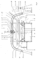
- FIG. 1 shows a table 1 from the front, on which a bumper 2 of a passenger car is stretched in such a way that its side parts 3, 4 point obliquely downwards to the side of the table 1.
- a rail 5 which extends approximately according to the bumper 2, is designed like a bridge and has both ends on the floor.
- a carriage 6 On the rail 5, a carriage 6 is arranged to be movable in the longitudinal direction of the rail 5. This carriage 6 carries a carriage 7 which is held transversely to the rail 5 between rollers 8, 9, 10, 11 of the carriage 6.
- a servomotor 12 is used to move the carriage 7.
- a sensor 13 of the carriage 7 is constantly in contact with the bumper 2 and can control the servomotor 12 via a control system such that a treatment device 14, in this example a corona discharge device, always remains at a constant distance from the Has bumper 2.
- the table 1 has a table top 15, to which two toggle levers 16, 17 are articulated, which can be actuated by a common spindle 18 by means of a hand crank 19 and which has threads with different directions of rotation for the two toggle levers 16, 17, so that both toggle levers 16, 17 can be compressed or spread at the same time.
- each side of the table 1 there is a baffle plate 20, 21 which extends to the end of each side part 3, 4 of the bumper 2 and serves to guide the sensor 13 when the carriage 6 extends beyond the respective end of the bumper 2 has moved.
- Proximity switches 22, 23, which are on the rail 5 are used to switch off the feed of the carriage 5 as soon as it has reached the respective end of the bumper 2.
- a limit switch 24, 25 is again arranged behind each proximity switch 22, 23 in the direction of movement, by means of which the carriage feed is switched off if the respective proximity switch 22, 23 should fail.
- a board 26 with support brackets 27, 28, 29 is fastened on the table 1.
- this board 26 is to be exchanged for another which has support blocks 27, 28, 29 adapted to the bumper 2.
- a dashboard 30 is shown in dash-dotted lines next to the rail 5 and has the control electronics and the operating switches.
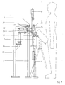
- FIG. 2 shows that the carriage 7 is located in front of the carriage 6.
- the table 1 has also advanced somewhat, so that the bumper 2 is located below the treatment device 14.
- the sensor 13, which actuates a potentiometer 31, which serves to control the servomotor 12, can also be seen in FIG.
- a feed motor 32 is provided on the carriage 6, which drives a pinion 33.
- This pinion 33 meshes in a rack 34 which extends in the longitudinal direction of the rail 5.
- a holding frame 35 which additionally supports the rail 5 and has a support bracket 36 for the cables leading to the carriage 6.
Landscapes
- Engineering & Computer Science (AREA)
- General Engineering & Computer Science (AREA)
- Mechanical Engineering (AREA)
- Physics & Mathematics (AREA)
- Plasma & Fusion (AREA)
- Treatments Of Macromolecular Shaped Articles (AREA)
- Automobile Manufacture Line, Endless Track Vehicle, Trailer (AREA)
- Vehicle Cleaning, Maintenance, Repair, Refitting, And Outriggers (AREA)
- Power Steering Mechanism (AREA)
- Moulds For Moulding Plastics Or The Like (AREA)
- Physical Or Chemical Processes And Apparatus (AREA)
Abstract
Description
- Die Erfindung betrifft eine Vorrichtung zur Oberflächenbehandlung einer Kraftfahrzeugstoßstange mittels einer Behandlungseinrichtung, insbesondere einer Koronaentladungseinrichtung.
- Stoßstangen von Kraftfahrzeugen müssen oftmals über ihre gesamte Länge behandelt werden, um beispielsweise bei Kunststoffstoßstangen die Oberfläche zum Aufkleben eines Zierstreifens oder einer Gummiauflage anzurauhen. Hierzu wird derzeit von Hand ein Koronaentladungsgerät über die zu behandelnde Fläche geführt Dieser Bearbeitungsgang ist zeitaufwendig und für den Arbeiter unangenehm auszuführen. Zusätzlich besteht ein gesundheitliches Risiko, weil man sich beim Führen des Koronaentladungsgerätes zwangsläufig in unmittelbarer Nähe der elektrischen Entladungen befinden muß, so daß die Gefahr des Einatmens von durch die Entladungen entstehendem Ozon besteht. Wird für diese Arbeiten ein Roboter eingesetzt, so sind für die Anschaffung des Roboters hohe Kosten erforderlich.
- Der Erfindung liegt die Aufgabe zugrunde, eine Vorrichtung der eingangs genannten Art so zu gestalten, daß möglichst rasch und ohne gesundheitliche Risiken für die Bedienperson Stoßstangen behandelt werden können.
- Diese Aufgabe wird bei der Vorrichtung erfindungsgemäß gelöst durch einen Tisch zum Aufspannen der Stoßstange in eine mit ihren beiden Seitenteilen nach unten weisende Position und eine entsprechend der Stoßstange verlaufende Schiene mit einem die Behandlungseinrichtung tragenden, angetriebenen Wagen.
- Eine solche Vorrichtung erlaubt es, die Stoßstangen ohne das Führen einer Behandlungseinrichtung von Hand zu behandeln, indem der Wagen mit der Behandlungseinrichtung auf der Schiene entlang der Stoßstange verfahren wird. Dadurch ist eine gleichmäßige und rasche Behandlung möglich. Die mit ihren Seitenteilen nach unten weisende Andordnung der jeweiligen Stoßstange ermöglicht es, die zu behandelnde Oberfläche ohne Mühe zu beobachten, so daß eine einfache Kontrolle der vorgenommenen Behandlung sichergestellt ist. Weiterhin ist das Aufspannen der Stoßstange bei einer solchen Anordnung sehr einfach.
- Eine besonders vorteilhafte Ausgestaltung der Erfindung besteht darin, daß der Wagen einen quer zur Haupterstreckungsrichtung der Schiene verschieblichen, die Behandlungseinrichtung tragenden Schlitten und einen Fühler zum Steuern des Abstandes des Schlittens und damit der Behandlungseinrichtung von der Stoßstange aufweist. Hierdurch wird erreicht, daß die Schiene nicht mehr genau dem Verlauf der Stoßstange entsprechen muß, da Abstandsänderungen zwischen Stoßstange und Schiene durch die Querverfahrbarkeit des Schlittens ausgeglichen werden. Dadurch können mit der erfindungsgemäßen Vorrichtung unterschiedliche Stoßstangen behandelt werden. Der Schlitten könnte mit einer Feder zur Stoßstange hin vorgespannt und vom Fühler auf einen festgelegten Abstand gehalten sein. Die Vorrichtung arbeitet jedoch besonders reibungsarm und schwingungsfrei, wenn der Fühler einen entlang der Stoßstange verschieblichen, ein Potentiometer betätigenden Fühlfinger hat. Weiterhin kann durch diese Anordnung erreicht werden, daß der Fühler nur mit einer geringen und gleichbleibenden Kraft gegen die Stoßstange druckt, so daß auch eine dünnwandige Stoßstange nicht verformt wird.
- Konstruktiv besonders einfach ist die Vorrichtung gestaltet, wenn die Schiene als mit ihren beiden Enden auf dem Boden stehende Brücke ausgebildet ist.
- Zum Aufspannen und Entnehmen einer Stoßstange wird man üblicherweise den Tisch als Hubtisch ausbilden. Dieser ist besonders einfach ausgebildet, wenn er eine mittels zweier Kniehebel höhenverfahrbare Tischplatte aufweist.
- Die beiden erforderlichen Kniehebel können gemeinsam über beispielsweise eine Handkurbel mittels nur einer Spindel verstellt werden, wenn gemäß einer anderen Ausgestaltung der Erfindung die beiden Kniehebel von einer gemeinsamen Spindel betätigbar sind, welche an ihren beiden, die Kniehebel betätigenden Enden Gewinde mit unterschiedlichem Drehsinn aufweist.
- Die Behandlungseinrichtung kann bis über die beiden Enden der Stoßstange fahren, ohne daß dabei der Fühler sich ins Leere bewegt, wenn an beiden Seiten des Tisches im Bereich der Enden der Stoßstange Auflaufbleche zum Abstützen des Fühlers nach überfahren des jeweiligen Stoßstangenendes vorgesehen sind und wenn auf der Schiene zum Abschalten der Vorschubbewegung des Wagens im Bereich beider Stoßstangenenden jeweils ein entlang der Schiene verstellbarer Näherungsschalter vorgesehen ist.
- Für den Fall eines Versagens der Näherungsschalter kommt es dennoch kurz nach Erreichen der Endstellung der jeweiligen Stoßstange zu einem zuverlässigen Abschalten des Vorschubs des Wagens, wenn in Richtung jedes Endes der Stoßstange gesehen jeweils hinter jedem Näherungsschalter ein Endschalter auf der Schiene vorgesehen ist.
- Der Wagen kann auf verschiedene Weise angetrieben werden, beispielsweise durch eine in der Schiene umlaufende Kette. Besonders einfach ist der Antrieb jedoch, wenn der Wagen zum Verfahren entlang der Schienen einen ein Ritzel antreibenden Vorschubmotor aufweist und das Ritzel in eine entlang der Schiene geführte Zahnstange eingreift.
- Für die Querbewegung des Schlittens wird vorteilhafterweise ein Stellmotor vorgesehen.
- Besonders einfach ist der Antrieb des Schlittens gestaltet, wenn der Stellmotor fest auf dem Schlitten angeordnet ist und eine relativ zum Schlitten unverschiebbare Hubspindel antreibt, welche in eine am Wagen unverschiebbar befestigte Spindelmutter geschraubt ist.
- Die Erfindung läßt zahlreiche Ausführungsformen zu. Zur weiteren Verdeutlichung ihres Grundprinzips ist eine davon in der Zeichnung dargestellt und wird nachfolgend beschieben. In ihr zeigen die
- Fig. 1 eine Vorderansicht der erfindungsgemäßen Vorrichtung,
- Fig. 2 eine Seitenansicht der Vorrichtung.
- Die Figur 1 zeigt von vorn einen Tisch 1, auf dem eine Stoßstange 2 eines Personenkraftwagens derart aufgespannt ist, daß sie mit ihren Seitenteilen 3, 4 seitlich des Tisches 1 schräg nach unten weist. Oberhalb des Tisches 1 befindet sich eine Schiene 5, welche in etwa entsprechend der Stoßstange 2 verläuft, brückenartig ausgebildet ist und mit ihren beiden Enden auf dem Boden steht.
- Auf der Schiene 5 ist ein Wagen 6 in Längserstreckung der Schiene 5 verfahrbar angeordnet. Dieser Wagen 6 trägt einen Schlitten 7, welcher quer zur Schiene 5 verfahrbar zwischen Rollen 8, 9, 10, 11 des Wagens 6 gehalten ist. Zum Verfahren des Schlittens 7 dient ein Stellmotor 12. Ein Fühler 13 des Schlittens 7 liegt ständig gegen die Stoßstange 2 an und vermag über eine Steuerung den Stellmotor 12 so anzusteuern, daß eine Behandlungseinrichtung 14, bei diesem Beispiel eine Koronaentladeeinrichtung, stets gleichbleibenden Abstand von der Stoßstange 2 hat.
- Der Tisch 1 hat eine Tischplatte 15, an welcher zwei Kniehebel 16, 17 angelenkt sind, die von einer gemeinsamen Spindel 18 mittels einer Handkurbel 19 betätigbar sind und für die beiden Kniehebel 16, 17 Gewinde mit unterschiedlichem Drehsinn aufweist, so daß beide Kniehebel 16, 17 gleichzeitig zusammengedrückt oder gespreizt werden.
- An jeder Seite des Tisches 1 ist jeweils ein Auflaufblech 20, 21 angeordnet, welches jeweils bis gegen das Ende jedes Seitenteiles 3, 4 der Stoßstange 2 reicht und zur Führung des Fühlers 13 dient, wenn sich der Wagen 6 bis über das jeweilige Ende der Stoßstange 2 bewegt hat. Näherungsschalter 22, 23, welche auf der Schiene 5 ange ordnet sind, dienen dazu, den Vorschub des Wagens 5 abzuschalten, sobald dieser das jeweilige Ende der Stoßstange 2 erreicht hat. In Bewegungsrichtung jeweils hinter jedem Näherungsschalter 22, 23 ist nochmals ein Endschalter 24, 25, angeordnet durch den der Wagenvorschub abgeschaltet wird, wenn der jeweilige Näherungsschalter 22, 23 versagen sollte.
- Zur Halterung der Stoßstange 2 ist auf dem Tisch 1 ein Brett 26 mit Auflageböcken 27, 28, 29 befestigt. Dieses Brett 26 ist bei Behandlung einer anders geformten Stoßstange 2 gegen ein anderes auszutauschen, welches der Stoßstange 2 angepaßte Auflageböcke 27, 28, 29 aufweist.
- Strichpunktiert ist neben der Schiene 5 ein Schaltpult 30 dargestellt, welches die Steuerelektronik und die Bedienschalter aufweist.
- Die in Figur 2 gezeigte Seitenansicht läßt erkennen, daß sich der Schlitten 7 räumlich vor dem Wagen 6 befindet. Entsprechend ist natürlich auch der Tisch 1 etwas vorgerückt, so daß sich die Stoßstange 2 unterhalb der Behandlungseinrichtung 14 befindet. Zu erkennen ist in Figur 2 weiterhin den Fühler 13, welcher ein Potentiometer 31 betätigt, das zum Steuern des Stellmotors 12 dient.
- Zum Antrieb des Wagens 6 ist am Wagen 6 ein Vorschubmotor 32 vorgesehen, welcher ein Ritzel 33 antreibt. Dieses Ritzel 33 kämmt in einer Zahnstange 34, die in Längsrichtung der Schiene 5 verläuft. Hinter der Schiene 5 ist ein Halterahmen 35 angeordnet, der die Schiene 5 zusätzlich abstützt und einen Auflagebock 36 für die zum Wagen 6 führenden Kabel aufweist.
- Nicht dargestellt sind zusätzliche Schaltnocken auf der Schiene 5, durch die ein Wegfahren und erneutes Heranfahren der Behandlungseinrichtung 14 von der Stoßstange 2 und zurück zu ihr gesteuert werden kann. Das ist erforderlich, wenn in der Stoßstange 2 beispielsweise Durchbrechungen für die Montage von Blinkern vorgesehen sind.
- 1 Tisch
2 Stoßstange
3 Seitenteil
4 Seitenteil
5 Schiene
6 Wagen
7 Schlitten
8 Rolle
9 Rolle
10 Rolle
11 Rolle
12 Stellmotor
13 Fühler
14 Behandlungseinrichtung
15 Tischplatte
16 Kniehebel
17 Kniehebel
18 Spindel
19 Handkurbel
20 Auflaufblech
21 Auflaufblech
22 Näherungsschalter
23 Näherungsschalter
24 Endschalter
25 Endschalter
26 Brett
27 Auflagebock
28 Auflagebock
29 Auflagebock
30 Schaltpult
31 Potentiometer
32 Vorschubmotor
33 Ritzel
34 Zahnstange
35 Halterahmen
36 Haltebock
Claims (11)
Priority Applications (1)
| Application Number | Priority Date | Filing Date | Title |
|---|---|---|---|
| AT88113567T ATE77295T1 (de) | 1987-08-27 | 1988-08-20 | Vorrichtung zur oberflaechenbehandlung einer kraftfahrzeugstossstange. |
Applications Claiming Priority (2)
| Application Number | Priority Date | Filing Date | Title |
|---|---|---|---|
| DE19873728585 DE3728585A1 (de) | 1987-08-27 | 1987-08-27 | Vorrichtung zur oberflaechenbehandlung einer kraftfahrzeugstossstange |
| DE3728585 | 1987-08-27 |
Publications (3)
| Publication Number | Publication Date |
|---|---|
| EP0304832A2 true EP0304832A2 (de) | 1989-03-01 |
| EP0304832A3 EP0304832A3 (en) | 1990-03-07 |
| EP0304832B1 EP0304832B1 (de) | 1992-06-17 |
Family
ID=6334600
Family Applications (1)
| Application Number | Title | Priority Date | Filing Date |
|---|---|---|---|
| EP88113567A Expired - Lifetime EP0304832B1 (de) | 1987-08-27 | 1988-08-20 | Vorrichtung zur Oberflächenbehandlung einer Kraftfahrzeugstossstange |
Country Status (4)
| Country | Link |
|---|---|
| EP (1) | EP0304832B1 (de) |
| AT (1) | ATE77295T1 (de) |
| DE (2) | DE3728585A1 (de) |
| ES (1) | ES2031969T3 (de) |
Families Citing this family (1)
| Publication number | Priority date | Publication date | Assignee | Title |
|---|---|---|---|---|
| CN113097963B (zh) * | 2021-04-09 | 2022-07-05 | 重庆华美电力设备有限责任公司 | 一种配电柜用避雷针快速收放导电盒 |
Family Cites Families (3)
| Publication number | Priority date | Publication date | Assignee | Title |
|---|---|---|---|---|
| DE3627864A1 (de) * | 1985-08-16 | 1987-04-30 | Rudolf Hall | Verfahren, vorrichtung und deren herstellungsverfahren zur corona-behandlung von formteilen |
| DE3532813A1 (de) * | 1985-09-13 | 1987-03-26 | Kr Oberflaechentech Gmbh | Vorrichtung zur corona-behandlung von formteilen |
| DE3637651A1 (de) * | 1985-11-08 | 1987-05-14 | Toyoda Gosei Kk | Gegenelektrode fuer coronaentladung |
-
1987
- 1987-08-27 DE DE19873728585 patent/DE3728585A1/de not_active Withdrawn
-
1988
- 1988-08-20 EP EP88113567A patent/EP0304832B1/de not_active Expired - Lifetime
- 1988-08-20 ES ES198888113567T patent/ES2031969T3/es not_active Expired - Lifetime
- 1988-08-20 DE DE8888113567T patent/DE3872108D1/de not_active Expired - Fee Related
- 1988-08-20 AT AT88113567T patent/ATE77295T1/de not_active IP Right Cessation
Also Published As
| Publication number | Publication date |
|---|---|
| ES2031969T3 (es) | 1993-01-01 |
| ATE77295T1 (de) | 1992-07-15 |
| DE3872108D1 (de) | 1992-07-23 |
| EP0304832B1 (de) | 1992-06-17 |
| EP0304832A3 (en) | 1990-03-07 |
| DE3728585A1 (de) | 1989-03-09 |
Similar Documents
| Publication | Publication Date | Title |
|---|---|---|
| EP1905522B1 (de) | Bearbeitungsmaschine mit einstellbarer Auflageeinheit | |
| WO2017084847A1 (de) | Vorrichtung zum einspannen von bauteilen in einer montagestrasse mit mehreren von synchronen schub-/drehbewegungen erzeugenden einspanneinrichtungen | |
| DE102021112047A1 (de) | Verfahreinheit zum Verfahren von zwei Lötbaugruppen zur Bearbeitung von Leiterplatten und Lötanlage zum selektiven Wellenlöten mit einer Verfahreinheit | |
| EP0304832B1 (de) | Vorrichtung zur Oberflächenbehandlung einer Kraftfahrzeugstossstange | |
| DE102006008216A1 (de) | Vorrichtung und Verfahren zur lagegenauen Positionierung zumindest einer Fahrzeugkomponente an einem Fahrzeug | |
| EP0898191A1 (de) | Koaxialtrieb für den Objekttisch eines Mikroskops | |
| DE202020104472U1 (de) | Vorrichtung zum Tragen von Bauteilen in einer Montagestraße | |
| DE19645794A1 (de) | Zuführ- und Entnahmeeinrichtung für Blechteile an einer Pressenlinie, Transferpresse, Großteilstufenpresse o. dgl. Pressenanlage | |
| DE19614657C2 (de) | Werkstückträgertransportvorrichtung mit einem umlaufenden Transportband | |
| EP2635399A2 (de) | Vorrichtung zum bearbeiten eines grossformatigen werkstücks | |
| DE4132099C1 (de) | ||
| AT402037B (de) | Vorrichtung zum spalten von holzstücken | |
| DE102004017428B4 (de) | Vorrichtung zum Umlenken von Einzelbahnen | |
| DE10345685B4 (de) | Vorrichtung zum Transport von Werkstücken | |
| WO2015018580A1 (de) | Plattenaufteilanlage | |
| EP0695635A2 (de) | Vorrichtung zum Befestigen von Aufzügen auf Druckzylindern | |
| DE202005003364U1 (de) | Vorrichtung zum Entnehmen und Beladen eines Gegenstandes | |
| DE4031838A1 (de) | Rollenpruefstand fuer ein kraftfahrzeug | |
| WO2018015536A1 (de) | Bearbeitungsvorrichtung und bearbeitungsverfahren | |
| DE10348643B3 (de) | Einrichtung zum Transport von Werkstücken | |
| AT408327B (de) | Abschaltvorrichtung an werkzeugmaschinen, insbesondere an mehrseitenhobelmaschinen | |
| DE10062818B4 (de) | Vorrichtungen und ein Verfahren zur Ausrichtung von Bogen | |
| EP0703170A1 (de) | Stellantrieb für Maschinenaggregate | |
| DE202025100839U1 (de) | Flugwerkvorrichtung | |
| EP0379020A1 (de) | Schaltvorrichtung zum Ein- und Ausschalten von Plattensägen |
Legal Events
| Date | Code | Title | Description |
|---|---|---|---|
| PUAI | Public reference made under article 153(3) epc to a published international application that has entered the european phase |
Free format text: ORIGINAL CODE: 0009012 |
|
| AK | Designated contracting states |
Kind code of ref document: A2 Designated state(s): AT BE CH DE ES FR GB GR IT LI LU NL SE |
|
| PUAL | Search report despatched |
Free format text: ORIGINAL CODE: 0009013 |
|
| AK | Designated contracting states |
Kind code of ref document: A3 Designated state(s): AT BE CH DE ES FR GB GR IT LI LU NL SE |
|
| 17P | Request for examination filed |
Effective date: 19900427 |
|
| 17Q | First examination report despatched |
Effective date: 19910821 |
|
| GRAA | (expected) grant |
Free format text: ORIGINAL CODE: 0009210 |
|
| AK | Designated contracting states |
Kind code of ref document: B1 Designated state(s): AT BE CH DE ES FR GB GR IT LI LU NL SE |
|
| PG25 | Lapsed in a contracting state [announced via postgrant information from national office to epo] |
Ref country code: GR Free format text: LAPSE BECAUSE OF FAILURE TO SUBMIT A TRANSLATION OF THE DESCRIPTION OR TO PAY THE FEE WITHIN THE PRESCRIBED TIME-LIMIT Effective date: 19920617 |
|
| REF | Corresponds to: |
Ref document number: 77295 Country of ref document: AT Date of ref document: 19920715 Kind code of ref document: T |
|
| GBT | Gb: translation of ep patent filed (gb section 77(6)(a)/1977) | ||
| PGFP | Annual fee paid to national office [announced via postgrant information from national office to epo] |
Ref country code: GB Payment date: 19920723 Year of fee payment: 5 |
|
| REF | Corresponds to: |
Ref document number: 3872108 Country of ref document: DE Date of ref document: 19920723 |
|
| PGFP | Annual fee paid to national office [announced via postgrant information from national office to epo] |
Ref country code: SE Payment date: 19920724 Year of fee payment: 5 |
|
| PGFP | Annual fee paid to national office [announced via postgrant information from national office to epo] |
Ref country code: FR Payment date: 19920729 Year of fee payment: 5 |
|
| PGFP | Annual fee paid to national office [announced via postgrant information from national office to epo] |
Ref country code: BE Payment date: 19920731 Year of fee payment: 5 |
|
| PGFP | Annual fee paid to national office [announced via postgrant information from national office to epo] |
Ref country code: LU Payment date: 19920805 Year of fee payment: 5 |
|
| PGFP | Annual fee paid to national office [announced via postgrant information from national office to epo] |
Ref country code: ES Payment date: 19920806 Year of fee payment: 5 |
|
| ET | Fr: translation filed | ||
| PGFP | Annual fee paid to national office [announced via postgrant information from national office to epo] |
Ref country code: NL Payment date: 19920831 Year of fee payment: 5 Ref country code: AT Payment date: 19920831 Year of fee payment: 5 |
|
| ITF | It: translation for a ep patent filed | ||
| PGFP | Annual fee paid to national office [announced via postgrant information from national office to epo] |
Ref country code: CH Payment date: 19921117 Year of fee payment: 5 |
|
| EPTA | Lu: last paid annual fee | ||
| REG | Reference to a national code |
Ref country code: ES Ref legal event code: FG2A Ref document number: 2031969 Country of ref document: ES Kind code of ref document: T3 |
|
| PLBE | No opposition filed within time limit |
Free format text: ORIGINAL CODE: 0009261 |
|
| STAA | Information on the status of an ep patent application or granted ep patent |
Free format text: STATUS: NO OPPOSITION FILED WITHIN TIME LIMIT |
|
| 26N | No opposition filed | ||
| PG25 | Lapsed in a contracting state [announced via postgrant information from national office to epo] |
Ref country code: LU Free format text: LAPSE BECAUSE OF NON-PAYMENT OF DUE FEES Effective date: 19930820 Ref country code: GB Effective date: 19930820 Ref country code: AT Effective date: 19930820 |
|
| PG25 | Lapsed in a contracting state [announced via postgrant information from national office to epo] |
Ref country code: SE Effective date: 19930821 Ref country code: ES Free format text: LAPSE BECAUSE OF NON-PAYMENT OF DUE FEES Effective date: 19930821 |
|
| PG25 | Lapsed in a contracting state [announced via postgrant information from national office to epo] |
Ref country code: LI Effective date: 19930831 Ref country code: CH Effective date: 19930831 Ref country code: BE Effective date: 19930831 |
|
| PGFP | Annual fee paid to national office [announced via postgrant information from national office to epo] |
Ref country code: DE Payment date: 19931014 Year of fee payment: 6 |
|
| BERE | Be: lapsed |
Owner name: SCHLITZER LOTHAR Effective date: 19930831 |
|
| PG25 | Lapsed in a contracting state [announced via postgrant information from national office to epo] |
Ref country code: NL Effective date: 19940301 |
|
| NLV4 | Nl: lapsed or anulled due to non-payment of the annual fee | ||
| GBPC | Gb: european patent ceased through non-payment of renewal fee |
Effective date: 19930820 |
|
| PG25 | Lapsed in a contracting state [announced via postgrant information from national office to epo] |
Ref country code: FR Effective date: 19940429 |
|
| REG | Reference to a national code |
Ref country code: CH Ref legal event code: PL |
|
| REG | Reference to a national code |
Ref country code: FR Ref legal event code: ST |
|
| EUG | Se: european patent has lapsed |
Ref document number: 88113567.7 Effective date: 19940310 |
|
| PG25 | Lapsed in a contracting state [announced via postgrant information from national office to epo] |
Ref country code: DE Effective date: 19950503 |
|
| REG | Reference to a national code |
Ref country code: ES Ref legal event code: FD2A Effective date: 19990503 |
|
| PG25 | Lapsed in a contracting state [announced via postgrant information from national office to epo] |
Ref country code: IT Free format text: LAPSE BECAUSE OF NON-PAYMENT OF DUE FEES;WARNING: LAPSES OF ITALIAN PATENTS WITH EFFECTIVE DATE BEFORE 2007 MAY HAVE OCCURRED AT ANY TIME BEFORE 2007. THE CORRECT EFFECTIVE DATE MAY BE DIFFERENT FROM THE ONE RECORDED. Effective date: 20050820 |