EP0304555B1 - Dispositif pour l'isolation phonique d'un transporteur horizontal - Google Patents
Dispositif pour l'isolation phonique d'un transporteur horizontal Download PDFInfo
- Publication number
- EP0304555B1 EP0304555B1 EP88108472A EP88108472A EP0304555B1 EP 0304555 B1 EP0304555 B1 EP 0304555B1 EP 88108472 A EP88108472 A EP 88108472A EP 88108472 A EP88108472 A EP 88108472A EP 0304555 B1 EP0304555 B1 EP 0304555B1
- Authority
- EP
- European Patent Office
- Prior art keywords
- housing
- protection device
- noise protection
- stands
- housing part
- Prior art date
- Legal status (The legal status is an assumption and is not a legal conclusion. Google has not performed a legal analysis and makes no representation as to the accuracy of the status listed.)
- Expired - Lifetime
Links
Images
Classifications
-
- B—PERFORMING OPERATIONS; TRANSPORTING
- B65—CONVEYING; PACKING; STORING; HANDLING THIN OR FILAMENTARY MATERIAL
- B65G—TRANSPORT OR STORAGE DEVICES, e.g. CONVEYORS FOR LOADING OR TIPPING, SHOP CONVEYOR SYSTEMS OR PNEUMATIC TUBE CONVEYORS
- B65G21/00—Supporting or protective framework or housings for endless load-carriers or traction elements of belt or chain conveyors
- B65G21/10—Supporting or protective framework or housings for endless load-carriers or traction elements of belt or chain conveyors movable, or having interchangeable or relatively movable parts; Devices for moving framework or parts thereof
- B65G21/12—Supporting or protective framework or housings for endless load-carriers or traction elements of belt or chain conveyors movable, or having interchangeable or relatively movable parts; Devices for moving framework or parts thereof to allow adjustment of position of load-carrier or traction element as a whole
Definitions
- the invention relates to a noise protection device for a horizontal conveyor system, with a support structure and with several, supported by the support structure, the conveyor system together with the material conveyed thereon in the longitudinal direction at least partially enclosing walls in a tunnel-shaped manner from sound-absorbing material, which together form a sound-absorbing housing, at least one of which Walls are formed by a vertically adjustable cover plate.
- the invention relates to a noise protection device for single-track or multi-track transport devices such as transporters and conveyor belts for the beverage, food and luxury goods industry and for the pharmaceutical industry, and in particular to such transport devices which serve for the transport of bottles.
- Such a noise protection device is known for example from DE-GM 82 11 683.
- container filling plants in which the containers on horizontal conveyor systems pass through a number of work stations, such as cleaning machines, control stations, filling machines, sealing machines, labeling machines, etc.
- noise protection systems in particular in the form of sound-absorbing walls.
- the known noise protection device is constructed in such a way that it comprises a frame-like frame made of vertical posts which are connected to one another by longitudinal and transverse beams, the side walls of the noise protection device being fastened to this frame-like frame and the roof of the noise protection device being attachable to the frame construction .
- the invention is based in particular on the object of creating a simpler noise protection device of the type mentioned at the outset compared to the known prior art.
- the support structure is formed by uprights arranged on one side of the housing, on which at least the housing part facing these uprights is slidably mounted in the direction of the uprights.
- the housing part facing away from the stands is fixed immovably on the stand.
- the arrangement can be such that the entire housing is displaceably mounted on the stands.
- frame parts rigidly fastened to the stand carry the immovably fastened housing part.
- the immovably fastened housing part preferably comprises the side wall opposite the stand, the roof and preferably at least part of the lower partition, while the displaceable housing part comprises the side wall facing the stand, preferably at least part of the lower partition and an upper band section running in the direction of the roof comprises, which forms an overlap with the roof to form an acoustic seal in the closed state of the housing.
- the displaceable housing part is displaceable downwards from its closed position
- the mutually facing edges of the lower partitions of the immovable housing part and the displaceable housing part are preferably arranged close to one another, so that they are only a relatively narrow one Define a gap that allows liquids to drain out of the noise protection device. If necessary, the lower partitions can overlap to a small extent while maintaining a gap.
- the housing in which the entire housing is mounted displaceably on the stands, it is preferably provided that the housing can be displaced upwards from its functional position into its open position.
- the housing preferably comprises two opposite side walls, a closed roof connecting the two side walls and two lower partitions which run inwards from each side wall.
- the two housing parts in the case of the first alternative embodiment or the housing in the case of the second alternative embodiment are preferably each formed in one piece and consist of transparent plastic, preferably polycarbonate, in order to have a clear view of the interior of the tunnel-shaped noise protection device at all times.
- the displaceable housing or housing part is preferably guided on guide rails formed on the uprights, the guide rails preferably being formed either by U-shaped guide profiles in which the side edges of the guided housing part run, or the displaceable housing or housing part being connected to sliding sleeves , which are guided on guide tubes or guide rods attached to the stands.
- guide rails preferably being formed either by U-shaped guide profiles in which the side edges of the guided housing part run, or the displaceable housing or housing part being connected to sliding sleeves , which are guided on guide tubes or guide rods attached to the stands.
- other guide devices can also be provided if necessary.
- the displaceable housing or housing part can be moved, for example, by means of a pneumatic cylinder or via a motor drive. If, in a preferred embodiment of the invention, the housing or housing part to be moved is connected to one end of at least one traction rope, which runs around at least one deflection pulley attached to the stand and carries a counterweight at its other end, then in this case a pneumatic or motor drive are dispensed with and due to the smooth movement of the displacement, the housing or the displaceable housing part can easily be moved by hand.
- the noise protection device reduces the noise emission by the goods to be transported to a large extent with simple construction and reliable handling and also proves to be particularly advantageous from a hygienic point of view after it reliably prevents foreign bodies from the environment from being encapsulated due to the encapsulation of the interior from the ambient air attach to the goods to be transported.
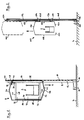
- the reference number 2 denotes the conveyor device of a conveyor system, which is not shown in any more detail.
- the conveyor 2 is located at a distance above the floor 4 and is surrounded by a noise protection housing 6 such that it encloses the entire transverse profile of the conveyor 2 including the goods conveyed thereon, such as bottles, with a sufficient distance.
- the housing 6 is supported on one or more vertical stands 8, each stand 8 being anchored to the floor 4 via suitable feet 10.
- each stand 8 being anchored to the floor 4 via suitable feet 10.
- One or two stands 8 can be provided for each housing 6, the stands 8 preferably being arranged in the abutting region of two housings 6 and thus each stand 8 carrying the opposite end regions of two adjacent housings 6.
- the stands 8 are designed as hollow profiles with a rectangular cross-section and have lateral U-shaped guide rails 12 which run in the longitudinal direction of the stands 8 and which serve to guide the movable parts of the housing 6.
- the housing 6 comprises a housing part 14 immovably fastened to the stands 8 and a movable housing part 16 guided displaceably on the stands 8.
- the immovable housing part 14 comprises the side wall 18 of the housing opposite the stand 8, the roof 20 the housing and one part of the bottom of the housing forming lower partition 22, which extends approximately to the vertical central plane of the housing and is inclined from the outside inwards.
- Side wall 18, roof 20 and lower partition 22 are formed in one piece and consist of transparent polycarbonate.
- a frame 24 extending transversely to the conveying direction is fastened, the lower, horizontal leg 26 of which runs below the conveying device 2, the upper, horizontal leg 28 of which runs above the conveying device 2 near the roof 20 of the housing 6, and the vertical leg 30 of which Stand 8 opposite ends of the legs 26 and 28 connects.
- the side wall 18 of the immovable housing part 14 is screwed onto the vertical leg 30 of the frame 24 by means of screws 32.
- An angled bracket 34 is attached to the upper portion of the stand 8, which is the stand 8 facing free end of the roof 20 of the housing 6 is fastened by screws 36 to the angled leg of the carrier 34.
- the movable housing part 16 comprises the side wall 38 facing the stand 8, an upper wall section. 40, which is angled inwards towards the roof 20 in the direction of the roof 20 and a lower partition 42, which extends from the side wall 38 to close to the vertical median plane of the housing 6, is inclined inwards and the lower partition 22 des opposite immovable housing part 14 to form a gap 44.
- the wall section 40 is in the closed state of the movable housing part 16 just below the free end of the roof 20, so that there is an overlap between the movable and immovable housing part 16 and 14 in this area.
- Side wall 38, wall section 40 and lower partition 42 are formed in one piece and, like the immovable housing part 14, are made of transparent polycarbonate.
- a rope pulley 46 is rotatably mounted about a horizontal axis, and a rope 48 laid around the rope pulley 46 is connected at one end to the movable housing part 16 and at the other end to a counterweight, not shown, which is guided inside the stand 8 and is dimensioned such that it corresponds to the weight of the movable housing part 16.
- the movable housing part 16 is shifted by hand in the direction of arrow A, for which purpose the side wall 38 can be provided with a corresponding handle, not shown in detail.
- the open position of the movable housing part 16 is shown in dashed lines in FIG. 1. In the open Position of the housing part 16, the conveyor 2 and the goods located thereon are completely accessible from the side of the stand 8.
- the described noise protection device in particular, for example, when the conveyor 2 is arranged near the floor 4, can easily be modified such that the movable housing part 16 is displaced upward from its closed position.
- the housing 106 as a whole is slidably mounted on the stand 108.
- the stand 108 is in turn supported on the floor 4 by means of suitable feet 110.
- the stands 108 can be arranged in particular in the region of two adjacent housings 106.
- the stand 108 has guide rods 112 running on both sides parallel to the stand, on which ball-bearing sliding sleeves 114, 116 are guided. These sliding sleeves 114, 116 are connected via fastening elements 128, 130 to the side wall 122 of the housing 106 facing the stator 108.
- the housing 122 is formed in one piece overall, consists of transparent polycarbonate and comprises the two side walls 118, 122, the roof 120 connecting the two side walls and optionally lower partitions 124, 126, which, however, are shorter than in the case of the exemplary embodiment according to FIGS. 1 and are so far apart from one another that when the housing 106 is raised, the conveyor 1 can emerge from the housing 106 between the two lower partitions 124, 126.
- the tunnel-shaped housing 106 is connected, for example in the area of the fastening element 128, to the one end of a rope 132 which is guided over a rope pulley 134 mounted on the upper end of the stand 108 and on at its other end carries a counterweight, not shown, which is displaceably arranged in the interior of the stand 108 and ensures appropriate weight compensation, so that the housing 106 remains in any desired vertical position without further measures.
- the housing 106 is manually moved from the lower position shown in FIG. 2 to the upper position shown in broken lines in FIG. 2, so that the conveyor 2 is completely released and is accessible from all sides .
- the noise protection device according to the invention is used in particular in the area of transporters of the bottle separators, where the bottles are separated in batches from multi-track belts and then individually run into the processing stations.
- Significant advantages of the noise protection device according to the invention are its small space requirement, its simple structure and the excellent accessibility to the conveying devices.
Claims (18)
- Dispositif de protection anti-bruit pour une installation de convoyage horizontal comportant une structure portante et plusieurs parois en matériau insonorisant, supportées par la structure portante et entourant en forme de tunnel, au moins partiellement, l'installation de convoyage ainsi que les produits qu'elle transporte en direction longitudinale, lesdites parois formant toutes ensemble un boîtier insonorisant, l'une de ces parois au moins étant constituée par une plaque de recouvrement verticalement mobile, caractérisé par le fait que la structure portante est constituée par des montants (8, 108) disposés d'un côté du boîtier (6, 106) et sur lesquels est montée de manière coulissante en direction desdits montants, an moins la partie (16,106) de ce boîtier tournée vers lesdits montants (8, 108).
- Dispositif de protection anti-bruit selon la revendication 1, caractérisé par le fait que la partie (14) du boîtier tournée à l'opposé des montants (8) est fixée sans possibilité de mouvement sur ledit montant (8).
- Dispositif de protection anti-bruit selon la revendication 2, caractérisé par le fait que des parties de cadre (24) fixées rigidement sur le montant (8) supportent la partie (14) du boîtier fixée sans possibilité de mouvement.
- Dispositif de protection anti-bruit selon la revendication 2 ou 3, caractérisé par le fait que la partie (14) du boîtier fixé sans possibilité de mouvement comprend la paroi latérale (18) opposée au montant (8), le toit (20), et de préférence au moins une partie (22) de la paroi inférieure.
- Dispositif de protection anti-bruit selon la revendication 4, caractérisé par le fait que la partie (16) coulissante du boîtier comprend la paroi latérale (38) orientée vers le montant (8), de préférence au moins une partie (42) de la paroi inférieure et une section (40) de la paroi supérieure s'étendant en direction du toit (20), la section (40) venant à l'état fermé du boîtier (6) en chevauchement avec le bord du toit (20).
- Dispositif de protection anti-bruit selon les revendications 4 et 5, caractérisé par le fait que la partie (16) coulissante du boîtier est mobile vers le bas à partir de sa position fermée et que les arêtes des parois inférieures (22, 42) orientées l'une vers l'autre, sont disposées de manière à se situer à proximité l'une de l'autre.
- Dispositif de protection anti-bruit selon l'une des revendications 2 à 6, caractérisé par le fait que les parties (14, 16) du boîtier forment chacune une seule pièce.
- Dispositif de protection anti-bruit selon la revendication 1, caractérisé par le fait que la totalité du boîtier (106) est montée de manière coulissante sur les montants (108).
- Dispositif de protection anti-bruit selon la revendication 8, caractérisé par le fait que le boîtier (106) peut coulisser vers le haut dans sa position d'ouverture à partir de sa position de fonctionnement.
- Dispositif de protection anti-bruit selon la revendication 9, caractérisé par le fait que le boîtier (106) comprend deux parois latérales se faisant face (118, 122), le toit (120) reliant les deux parois latérales, et éventuellement, deux parois inférieures (124, 126) qui s'étendent vers l'intérieur à partir de chacune des parois latérales.
- Dispositif de protection anti-bruit selon l'une des revendications 8 à 10, caractérisé par le fait que le boîtier (106) est réalisé en une seule pièce.
- Dispositif de protection anti-bruit selon l'une des revendications précédentes, caractérisé par le fait que le boîtier (6, 106) est réalisé de préférence en polycarbonate transparent.
- Dispositif de protection anti-bruit selon l'une des revendications précédentes, caractérisé par le fait que le boîtier mobile (106) ou la partie (16) du boîtier, est guidé sur des rails de guidage (12, 112) disposés sur les montants (8, 108).
- Dispositif de protection anti-bruit selon la revendication 13, caractérisé par le fait que les rails de guidage (12) sont constitués de profilés en forme de U.
- Dispositif de protection anti-bruit selon la revendication 13, caractérisé par le fait que le boîtier (106) ou la partie (16) du boîtier qui coulisse est relié à des douilles de coulissement (114, 116) lesquelles sont guidées sur des tubes ou des tringles de guidage (112) fixés sur les montants (8, 108).
- Dispositif de protection anti-bruit selon l'une des revendications 13 à 15, caractérisé par le fait que le boîtier (106) ou la partie (16) du boîtier qui coulisse est guidé sur les montants (8, 108) par des roulements à billes.
- Dispositif de protection anti-bruit selon l'une des revendications précédentes, caractérisé par le fait que le boîtier (106) ou la partie (16) du boîtier qui coulisse est relié à l'une des extrêmités d'au moins un câble de traction (48, 132), lequel passe autour d'au moins une poulie de renvoi (46, 134) fixée sur le montant (8, 108) et qui supporte à son autre extrémité un contre-poids.
- Dispositif de protection anti-bruit selon la revendication 17, caractérisé par le fait que le contre-poids est guidé à l'intérieur du montant (8, 108).
Priority Applications (1)
| Application Number | Priority Date | Filing Date | Title |
|---|---|---|---|
| AT88108472T ATE73104T1 (de) | 1987-08-24 | 1988-05-27 | Laermschutzvorrichtung fuer eine horizontalfoerderanlage. |
Applications Claiming Priority (2)
| Application Number | Priority Date | Filing Date | Title |
|---|---|---|---|
| DE8711472U | 1987-08-24 | ||
| DE8711472U DE8711472U1 (fr) | 1987-08-24 | 1987-08-24 |
Publications (2)
| Publication Number | Publication Date |
|---|---|
| EP0304555A1 EP0304555A1 (fr) | 1989-03-01 |
| EP0304555B1 true EP0304555B1 (fr) | 1992-03-04 |
Family
ID=6811369
Family Applications (1)
| Application Number | Title | Priority Date | Filing Date |
|---|---|---|---|
| EP88108472A Expired - Lifetime EP0304555B1 (fr) | 1987-08-24 | 1988-05-27 | Dispositif pour l'isolation phonique d'un transporteur horizontal |
Country Status (3)
| Country | Link |
|---|---|
| EP (1) | EP0304555B1 (fr) |
| AT (1) | ATE73104T1 (fr) |
| DE (2) | DE8711472U1 (fr) |
Family Cites Families (4)
| Publication number | Priority date | Publication date | Assignee | Title |
|---|---|---|---|---|
| FR2454986A1 (fr) * | 1979-04-27 | 1980-11-21 | Massicot Robert | Equipement isolant pour transporteurs |
| DE3136761A1 (de) * | 1981-09-16 | 1983-03-31 | Seitz-Werke Gmbh, 6550 Bad Kreuznach | Von einer ein- oder mehrteiligen haube abgedeckte foerdereinrichtung fuer flaschen und aehnliche behaelter |
| DE8211683U1 (de) * | 1982-04-23 | 1982-10-28 | Fa. Ulrich Hein, 4750 Unna-Massen | Lärmschutzkasten |
| FR2531560A1 (fr) * | 1982-08-04 | 1984-02-10 | Rionde Ets | Ensemble de capotage pour isolation phonique et sterile d'unites a bande transporteuse |
-
1987
- 1987-08-24 DE DE8711472U patent/DE8711472U1/de not_active Expired
-
1988
- 1988-05-27 AT AT88108472T patent/ATE73104T1/de not_active IP Right Cessation
- 1988-05-27 DE DE8888108472T patent/DE3868783D1/de not_active Expired - Lifetime
- 1988-05-27 EP EP88108472A patent/EP0304555B1/fr not_active Expired - Lifetime
Also Published As
| Publication number | Publication date |
|---|---|
| EP0304555A1 (fr) | 1989-03-01 |
| ATE73104T1 (de) | 1992-03-15 |
| DE3868783D1 (de) | 1992-04-09 |
| DE8711472U1 (fr) | 1987-11-19 |
Similar Documents
| Publication | Publication Date | Title |
|---|---|---|
| EP0237777B1 (fr) | Installation pour emballer dans des conditions stériles | |
| DE202012104466U1 (de) | Vorrichtung zum Bereitstellen von Formteilen in einer Getränkeabfüllanlage | |
| EP1338531A1 (fr) | Installation pour le transport de matériaux en vrac | |
| DE3422150A1 (de) | Foerdereinrichtung | |
| EP0737631B1 (fr) | Dispositif de distribution d'objets | |
| DE2336000C2 (de) | Endlosförderer zum Fördern und Zwischenspeichern von Stückgütern | |
| EP3119706B1 (fr) | Dispositif de transport et procédé de transport pour une installation de traitement de contenant | |
| EP0999154A1 (fr) | Transporteur à navettes | |
| DE102013107612A1 (de) | Fördervorrichtung | |
| EP1538112B1 (fr) | Installation pour le transport de produits en moyen d'une bande transporteuse sans fins | |
| EP0304555B1 (fr) | Dispositif pour l'isolation phonique d'un transporteur horizontal | |
| DE2430165C2 (de) | Vorrichtung zur Abdeckung eines Abschnitts von Gegenständen | |
| EP0599032A1 (fr) | Magasin de stockage pour récipients | |
| EP0436081A1 (fr) | Dispositif de transport | |
| DE3642764A1 (de) | Einrichtung zum zusammenfuehren von behaeltern vorzugsweise flaschen | |
| DE4330702A1 (de) | Verstellbare Geländerstütze sowie Förderstrecke mit verstellbarem Geländer | |
| DE2745875C2 (fr) | ||
| EP0305652B1 (fr) | Dispositif pour l'isolation phonique d'une machine à nettoyer les bouteilles | |
| DE3713524C1 (en) | Apparatus for intermediate storage of articles | |
| DE1532496A1 (de) | Austragsvorrichtung fuer Behaelter bei Behaelterbehandlungsmaschinen | |
| DE4314438C1 (de) | Transportvorrichtung für Massenartikel | |
| DE2531507C2 (de) | Vorrichtung zum Sortieren und Klassieren lebender Fische | |
| EP2396257B1 (fr) | Dispositif de déplacement à utiliser avec un transporteur | |
| DE60011878T2 (de) | Vorrichtung zur lagerung von kleidungsstücken | |
| DE2610658C3 (de) | Silo-Anlage, insbesondere für Ton und tonartige Massen |
Legal Events
| Date | Code | Title | Description |
|---|---|---|---|
| PUAI | Public reference made under article 153(3) epc to a published international application that has entered the european phase |
Free format text: ORIGINAL CODE: 0009012 |
|
| AK | Designated contracting states |
Kind code of ref document: A1 Designated state(s): AT BE CH DE ES FR GB GR IT LI LU NL SE |
|
| 17P | Request for examination filed |
Effective date: 19890220 |
|
| 17Q | First examination report despatched |
Effective date: 19910429 |
|
| GRAA | (expected) grant |
Free format text: ORIGINAL CODE: 0009210 |
|
| AK | Designated contracting states |
Kind code of ref document: B1 Designated state(s): AT BE CH DE ES FR GB GR IT LI LU NL SE |
|
| PG25 | Lapsed in a contracting state [announced via postgrant information from national office to epo] |
Ref country code: GR Free format text: LAPSE BECAUSE OF FAILURE TO SUBMIT A TRANSLATION OF THE DESCRIPTION OR TO PAY THE FEE WITHIN THE PRESCRIBED TIME-LIMIT Effective date: 19920304 Ref country code: ES Free format text: THE PATENT HAS BEEN ANNULLED BY A DECISION OF A NATIONAL AUTHORITY Effective date: 19920304 |
|
| REF | Corresponds to: |
Ref document number: 73104 Country of ref document: AT Date of ref document: 19920315 Kind code of ref document: T |
|
| REF | Corresponds to: |
Ref document number: 3868783 Country of ref document: DE Date of ref document: 19920409 |
|
| ET | Fr: translation filed | ||
| GBT | Gb: translation of ep patent filed (gb section 77(6)(a)/1977) | ||
| ITF | It: translation for a ep patent filed |
Owner name: MODIANO & ASSOCIATI S.R.L. |
|
| PG25 | Lapsed in a contracting state [announced via postgrant information from national office to epo] |
Ref country code: LU Free format text: LAPSE BECAUSE OF NON-PAYMENT OF DUE FEES Effective date: 19920531 |
|
| PLBE | No opposition filed within time limit |
Free format text: ORIGINAL CODE: 0009261 |
|
| STAA | Information on the status of an ep patent application or granted ep patent |
Free format text: STATUS: NO OPPOSITION FILED WITHIN TIME LIMIT |
|
| 26N | No opposition filed | ||
| EAL | Se: european patent in force in sweden |
Ref document number: 88108472.7 |
|
| REG | Reference to a national code |
Ref country code: GB Ref legal event code: IF02 |
|
| PGFP | Annual fee paid to national office [announced via postgrant information from national office to epo] |
Ref country code: NL Payment date: 20070516 Year of fee payment: 20 |
|
| PGFP | Annual fee paid to national office [announced via postgrant information from national office to epo] |
Ref country code: AT Payment date: 20070523 Year of fee payment: 20 |
|
| PGFP | Annual fee paid to national office [announced via postgrant information from national office to epo] |
Ref country code: SE Payment date: 20070524 Year of fee payment: 20 Ref country code: BE Payment date: 20070524 Year of fee payment: 20 Ref country code: CH Payment date: 20070524 Year of fee payment: 20 |
|
| PGFP | Annual fee paid to national office [announced via postgrant information from national office to epo] |
Ref country code: DE Payment date: 20070731 Year of fee payment: 20 |
|
| PGFP | Annual fee paid to national office [announced via postgrant information from national office to epo] |
Ref country code: GB Payment date: 20070523 Year of fee payment: 20 |
|
| PGFP | Annual fee paid to national office [announced via postgrant information from national office to epo] |
Ref country code: IT Payment date: 20070525 Year of fee payment: 20 |
|
| PGFP | Annual fee paid to national office [announced via postgrant information from national office to epo] |
Ref country code: FR Payment date: 20070518 Year of fee payment: 20 |
|
| BE20 | Be: patent expired |
Owner name: FIRMA ULRICH *HEIN Effective date: 20080527 |
|
| REG | Reference to a national code |
Ref country code: GB Ref legal event code: PE20 Expiry date: 20080526 |
|
| REG | Reference to a national code |
Ref country code: CH Ref legal event code: PL |
|
| EUG | Se: european patent has lapsed | ||
| NLV7 | Nl: ceased due to reaching the maximum lifetime of a patent |
Effective date: 20080527 |
|
| PG25 | Lapsed in a contracting state [announced via postgrant information from national office to epo] |
Ref country code: NL Free format text: LAPSE BECAUSE OF EXPIRATION OF PROTECTION Effective date: 20080527 |
|
| PG25 | Lapsed in a contracting state [announced via postgrant information from national office to epo] |
Ref country code: GB Free format text: LAPSE BECAUSE OF EXPIRATION OF PROTECTION Effective date: 20080526 |