EP0303897B1 - Wärmedämmung für Kühlhäuser - Google Patents
Wärmedämmung für Kühlhäuser Download PDFInfo
- Publication number
- EP0303897B1 EP0303897B1 EP88112638A EP88112638A EP0303897B1 EP 0303897 B1 EP0303897 B1 EP 0303897B1 EP 88112638 A EP88112638 A EP 88112638A EP 88112638 A EP88112638 A EP 88112638A EP 0303897 B1 EP0303897 B1 EP 0303897B1
- Authority
- EP
- European Patent Office
- Prior art keywords
- heat
- cap
- excluder
- sealing
- thermal insulation
- Prior art date
- Legal status (The legal status is an assumption and is not a legal conclusion. Google has not performed a legal analysis and makes no representation as to the accuracy of the status listed.)
- Expired - Lifetime
Links
- 238000009413 insulation Methods 0.000 title description 30
- 238000007789 sealing Methods 0.000 claims description 45
- 238000003780 insertion Methods 0.000 claims description 10
- 230000037431 insertion Effects 0.000 claims description 10
- 229920003023 plastic Polymers 0.000 claims description 5
- 239000004033 plastic Substances 0.000 claims description 5
- 235000013290 Sagittaria latifolia Nutrition 0.000 claims 2
- 235000015246 common arrowhead Nutrition 0.000 claims 2
- 239000011810 insulating material Substances 0.000 claims 1
- 229920001296 polysiloxane Polymers 0.000 description 4
- 241000233866 Fungi Species 0.000 description 2
- 239000011499 joint compound Substances 0.000 description 2
- 229920005830 Polyurethane Foam Polymers 0.000 description 1
- 230000006978 adaptation Effects 0.000 description 1
- 238000005452 bending Methods 0.000 description 1
- 230000015572 biosynthetic process Effects 0.000 description 1
- 238000004140 cleaning Methods 0.000 description 1
- 150000001875 compounds Chemical class 0.000 description 1
- 238000011161 development Methods 0.000 description 1
- 230000018109 developmental process Effects 0.000 description 1
- 235000013305 food Nutrition 0.000 description 1
- 230000009931 harmful effect Effects 0.000 description 1
- 230000003116 impacting effect Effects 0.000 description 1
- 238000009434 installation Methods 0.000 description 1
- 239000000463 material Substances 0.000 description 1
- 235000013372 meat Nutrition 0.000 description 1
- 238000000034 method Methods 0.000 description 1
- 230000035515 penetration Effects 0.000 description 1
- 239000011496 polyurethane foam Substances 0.000 description 1
- 230000036316 preload Effects 0.000 description 1
- 230000035945 sensitivity Effects 0.000 description 1
- 230000007704 transition Effects 0.000 description 1
- 238000005406 washing Methods 0.000 description 1
Images
Classifications
-
- E—FIXED CONSTRUCTIONS
- E04—BUILDING
- E04H—BUILDINGS OR LIKE STRUCTURES FOR PARTICULAR PURPOSES; SWIMMING OR SPLASH BATHS OR POOLS; MASTS; FENCING; TENTS OR CANOPIES, IN GENERAL
- E04H5/00—Buildings or groups of buildings for industrial or agricultural purposes
- E04H5/10—Buildings forming part of cooling plants
-
- F—MECHANICAL ENGINEERING; LIGHTING; HEATING; WEAPONS; BLASTING
- F25—REFRIGERATION OR COOLING; COMBINED HEATING AND REFRIGERATION SYSTEMS; HEAT PUMP SYSTEMS; MANUFACTURE OR STORAGE OF ICE; LIQUEFACTION SOLIDIFICATION OF GASES
- F25D—REFRIGERATORS; COLD ROOMS; ICE-BOXES; COOLING OR FREEZING APPARATUS NOT OTHERWISE PROVIDED FOR
- F25D23/00—General constructional features
- F25D23/06—Walls
- F25D23/062—Walls defining a cabinet
- F25D23/063—Walls defining a cabinet formed by an assembly of panels
Definitions
- the invention relates to thermal insulation for cold stores, cold rooms and cold rooms according to the preamble of claim 1.
- Cold stores are mostly insulated with thermal insulation elements made of rigid polyurethane foam in the form of plate-shaped wall elements, with which the walls and ceiling of the cold stores are clad.
- the plate-shaped wall elements are placed against each other so that joints remain between adjacent wall elements that have to be closed.
- the grouting is at least 40 km and more.
- these joints are closed by a sealing profile, which is made in one piece from plastic and is formed from an L-shaped or T-shaped web with an adjoining cap.
- corresponding recesses or grooves are formed on the end faces of the wall elements in which the sealing profiles are located can be arranged loosely with their L or T legs.
- the sealing profile with its L- or T-shaped part is first inserted into the corresponding recess in the end face of the wall element before the adjacent wall element can be connected.
- the adjacent wall element must be attached so that the L or T leg of the pre-assembled sealing profile gets into the corresponding recess of the wall element to be connected, whereby care must also be taken that the outer surface of the wall element is inserted in front of the cap and exactly between L - or T-leg of the sealing profile and the cap underside is fitted. This requires appropriate care and sensitivity of the personnel who create the thermal insulation of the cold store, damage to the thermal insulation elements should be avoided.
- the gaps between the sealing profiles and the wall elements placed against one another must then be filled with a permanently elastic joint compound, for which purpose silicone is used in particular.
- a joint seal is achieved with this permanently elastic mass, but silicone in particular has the disadvantage that it absorbs spores, so that fungi can form.
- the penetration of spores also leads to a discolouration of the silicone mass, so that over time the outside of the thermal insulation no longer offers an optically perfect appearance.
- the walls of the cold stores have to be cleaned periodically, which is done by high-pressure cleaners.
- knock-in profiles made of plastic, consisting of a insertable into the joint base profile with two legs for arrangement in the corresponding recesses of the adjacent wall elements and a knock-in profile with a joint-covering cap attached to their Has longitudinal edges roof-shaped sealing lips angled in the direction of the base profile and a protruding from the cap, provided with locking elements insertion strip, which can be pressed into a groove formed in the base part, also provided with locking elements and locked.
- the object of the invention is therefore to provide thermal insulation for cold stores which is free from the disadvantages described above.
- the thermal insulation according to the invention should be characterized in that it can be created more quickly and easily and in a material-saving manner by facilitating the jointing.
- an excellent sealing of the joints of adjacent thermal insulation elements should be guaranteed in a hygienically perfect manner, without the risk of damaging the insulating boards during assembly.
- the sealing profile is formed from two parts that can be plugged together, namely a base part and an impact profile strip.
- This leads to a considerable simplification of assembly as when assembling the wall elements after inserting the base part into the corresponding groove in the end face of the wall elements, the other wall element only has to be attached without threading the thermal insulation element between the leg and cap of the sealing profile.
- the profile can be hammered in from the outside under pressure on the base part already in the joint.
- the locking position for the turning profile in the base part is chosen so that the cap rests under pressure on the outer surface of the adjacent wall elements, so that a seal of the joint to the outside is ensured as a result of the cap which is in contact with pressure.
- the cap is expediently formed with downwardly projecting sealing lips and additional lips on both sides of the joint, which run continuously along the underside of the cap. Since the drive-in profile is made of plastic, the cap ends can deflect resiliently when the plug-in strip is driven in, so that in the assembled position the cap ends, with the projections formed on the underside, pretension the outer surface of the adjacent wall elements.
- the projections on the cap are expediently formed by sealing lips and additional lips which are angled obliquely downward from the plane of the cap and extend outward from the cap.
- these sealing lips and additional lips are pressed somewhat backwards, so that they then lie against both wall elements in a sealed manner along with their expediently rounded end edges along the joint.
- the distance from the upper edge of the leg of the base part to the lower edge of the cap is smaller than the thickness of the thermal insulation between the groove and the outer surface of the thermal insulation, this difference being approximately 2 to 3 mm in an advantageous embodiment. This ensures that the sealing lips are adequately sealed even in the event of any tolerance deviations in the components used.
- This resilient rearward bending of the sealing lip is further promoted if the sealing lips are connected in the manner of a joint to the drive-in profile, which is done in a technically simple manner in that longitudinal grooves are made in the transition region of the seal lip to the drive-in profile.
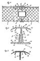
- the conventional thermal insulation shown in Figure 1 consists of butted wall elements 1, the butt joints 2 on the two outer sides of the thermal insulation are closed on the outside by sealing profiles 3.
- these sealing profiles 3 are formed in one piece from an L-shaped web 4 and a cap 5 connected to it, which has projections 6 formed on the underside adjacent to its two longitudinal edges, by means of which the cap rests on the longitudinal edges of the two thermal insulation elements 1.
- the strip-like sealing profile 3 is loosely received in grooves 7 made on the end faces of the thermal insulation elements 1.
- the sealing profile is first placed in the corresponding groove 7 of the end face after appropriate placement of the one thermal insulation element 1, or, in the case of jointing on both sides, both end profiles. Then the second thermal insulation element 1 is pushed laterally against the first thermal insulation element 1, care being taken to ensure that the thermal insulation element 1 reaches the underside of the cap and the L-leg of the web 4 of the sealing profile is not pressed out of the groove.
- This assembly requires a corresponding care of the operating personnel, in particular when both outer sides of the thermal insulation have to be grouted at the same time by means of appropriate sealing profiles.
- a permanently elastic joint compound in particular silicone, is introduced into the remaining gaps between the sealing profile and the thermal insulation elements.
- the joint sealing profile 8 is shown in FIG. This is formed in two parts and consists of a base part 9 and an impact profile 10.
- the impact profile 10 is designed such that it can be driven into the base part 9.
- the base part 9 is arranged in the grooves 7 of the adjacent wall elements 1 and is loosely seated within the grooves 7. Because of the division in two, assembly is extremely simple, because after arranging the base part 9 in a groove 7 of the one wall element 1, the other is only pushed on laterally got to. Then the impact profile is from the outside 10 indented. According to FIG.
- the turning profile has a cap 11, from which a plug-in strip 12 projects vertically downward, at the free end of which a catch 13 is formed, which in the exemplary embodiment shown has the shape of an arrowhead.
- a receiving web 15 protrudes from the plane of the two legs 14, which is formed from two opposite walls 16 and 17, which between them form a groove-shaped receiving space 18 for the projecting part 12 of the impact profile 10.
- the two walls 16 and 17 have catch projections 19 arranged opposite one another at their upper end, which delimit an inlet zone 20 which has an arrowhead shape between them and end in a recessed shoulder 21 which provides a catch surface for the catch 13 represents.
- the locking projections 19 formed with an inclined surface and the recessed shoulder form the locking member for the locking 13.
- the cap 11 of the impact profile 10 has a sealing lip 22 on each of its two longitudinal edges, which in the exemplary embodiment shown tapers towards its free end and the tip of which is rounded.
- the sealing lip 22 is connected in an articulated manner, which takes place by means of molded-in longitudinal grooves 23 in the region of the longitudinal edges.
- the cap 11 has an additional lip 26 on each of the longitudinal edges, which is angled more than the sealing lip 22 and protrudes slightly downward beyond the lower edges 25.
- the two thermal insulation elements 1 including the arrangement of the base part 9 within the grooves 7 of adjacent thermal insulation elements 1, only the turning profile 10 is placed from the outside and pressed into the base part 9 until the catch 13 engages over the latching surface 21 of the base part. Since the distance d between the groove 7 or the upper wall surface of the groove 7 and the associated outer surface of the Thermal insulation element 1 is greater than the distance from the upper edge 24 of the legs 14 to the lower edge 25 of the plug-in strip 10 in the latching position and in the untensioned state of the sealing profile 8, the two sealing lips 22 and additional lips 26 which are angled obliquely downward in the untensioned state become when the impact profile is turned in the base part 9 is bent upwards so that they press in the locking position with pretension on the outer surface of the two thermal insulation elements 1 and are in sealing contact with these surfaces.
- the base part 9 and the wrap-in profile 10 are made of plastic and are strand-shaped, so that the sealing profiles can be laid in strips between the joints. Since the sealing contact of the sealing lips is correspondingly large due to the preload, no additional grouting is required due to a permanently elastic mass.
Landscapes
- Engineering & Computer Science (AREA)
- Architecture (AREA)
- Civil Engineering (AREA)
- Structural Engineering (AREA)
- Chemical & Material Sciences (AREA)
- Combustion & Propulsion (AREA)
- Physics & Mathematics (AREA)
- Mechanical Engineering (AREA)
- Thermal Sciences (AREA)
- General Engineering & Computer Science (AREA)
- Building Environments (AREA)
- Packages (AREA)
Description
- Die Erfindung betrifft eine Wärmedämmung für Kühlhäuser, Kühlräume und Kühlzellen gemäß dem Oberbegriff des Patentanspruches 1.
- Die Isolierung von Kühlhäusern erfolgt überwiegend mit Wärmedämmelementen aus Polyurethan-Hartschaum in Form von plattenförmigen Wandelementen, mit denen Wände und Decke der Kühlhäuser verkleidet werden. Die plattenförmigen Wandelemente werden hierbei auf Stoß aneinander gesetzt, so daß zwischen benachbarten Wandelementen Fugen verbleiben, die verschlossen werden müssen. Bei durchschnittlich großen Kühlhäusern beläuft sich hierbei die Verfugung auf eine Länge von immerhin etwa 40 km und mehr. In herkömmlicher Weise werden diese Fugen durch ein Abdichtprofil geschlossen, welches einstückig aus Kunststoff hergestellt ist und aus einem L- oder T-förmigen Steg mit einer daran anschließenden Kappe ausgebildet ist. Zur Montage der Abdichtprofile in den Fugen sind an den stoßseitigen Stirnflächen der Wandelemente entsprechende Aussparungen bzw. Nuten ausgebildet, in denen die Abdichtprofile mit ihren L- oder T-Schenkeln lose angeordnet werden. Zur Montage ist es erforderlich, daß nach der Anordnung eines Wandelementes zuerst das Abichtprofil mit seinem L- oder T-förmigen Teil in die entsprechende Aussparung in der Stirnseite des Wandelementes eingesetzt wird, bevor das benachbarte Wandelement angeschlossen werden kann. Hierbei muß das benachbarte Wandelement so angesetzt werden, daß der L- oder T-Schenkel des bereits vormontierten Abdichtprofils in die entsprechende Aussparung des anzuschließenden Wandelementes gelangt, wobei zudem Sorge getragen werden muß, daß die Außenfläche des Wandelementes vor der Kappe eingeführt und exakt zwischen L- oder T-Schenkel des Abdichtprofiles und der Kappenunterseite eingepaßt wird. Dies erfordert entsprechende Sorgfalt und Feingefühl des die Wärmedämmung des Kühlhauses erstellenden Personals, sollen Beschädigungen der Wärmedämmelemente vermieden werden. In einem anschließenden Montagevorgang müssen dann noch die Spalte zwischen den Abdichtprofilen und den aneinander gesetzten Wandelementen durch eine dauerelastische Fugenmasse verfüllt werden, wozu insbesondere Silikon verwendet wird. Mit dieser dauerelastischen Masse wird zwar eine Fugenabdichtung erreicht, jedoch ist insbesondere Silikon mit dem Nachteil behaftet, daß es Sporen aufnimmt, so daß es zu Pilzbildungen kommen kann. Abgesehen von diesen hygienisch schädlichen Eigenschaften kommt es infolge eindringender Sporen auch zu einer Verfärbung der Silikonmasse, so daß im Laufe der Zeit die Außenseite der Wärmedämmung kein optisch einwandfreies Erscheinungsbild mehr bietet. Ferner müssen in Kühlhäusern, in denen Lebensmittel, insbesondere Fleisch gelagert und verarbeitet werden, die Wände der Kühlhäuser periodisch gereinigt werden, was durch Hochdruckreiniger erfolgt. Eine häufige Hochdruckreinigung führt allerdings zu einer allmählichen Ablösung bzw. Auswaschung der dauerelastischen Fugenmasse, so daß sich Wärmebrücken bzw. Kältebrücken bilden und sich in entstehenden Ritzen erst recht Sporen sammeln können, die zu einer Pilzbildung führen. Zusammenfassend ist festzuhalten,daß die bislang verwendeten Abdichtprofile mit erheblichen Montagenachteilen behaftet sind. Dies fällt insbesondere durch die erheblichen Längen von Fugen (bis zu 40 km und mehr) ins Gewicht. Es ist einleuchtend, daß für die Verfugung ein entsprechender Materialbedarf an dauerelastischer Masse vorhanden ist, was sich letztendlich auch in den Installationskosten der Wärmedämmung niederschlägt.
- Im Zusammenhang mit der Verbindung von Bauplatten sind ferner, z. B. aus der deutschen Offenlegungsschrift DE-A-19 56 170, Einschlagprofile aus Kunststoff bekannt, bestehend aus einem in die Fuge einsetzbaren Basisprofil mit zwei Schenkeln zur Anordnung in den entsprechenden Aussparungen der benachbarten Wandelemente und einem Einschlagprofil mit einer fugenüberdeckenden Kappe, die an ihren Längsrändern dachförmig in Richtung des Basisprofils abgewinkelte Dichtlippen aufweist und einer von der Kappe vorstehenden, mit Rastelementen versehenen Einsteckleiste, welche in eine im Basisteil ausgebildete, ebenfalls mit Rastelementen versehene Nut eindrück- und einrastbar ist.
- Diese Einschlagprofile haben den Nachteil, daß die relativ starre Kappe der Einschlagprofilleiste die Fugen nicht genügend gegen Feuchtigkeit abdichtet bzw. die empfindlichen Wandelemente beim Einschlagen beschädigt.
- Aufgabe der Erfindung ist es daher, eine Wärmedämmung für Kühlhäuser zu schaffen, die frei von den oben geschilderten Nachteilen ist. Insbesondere soll sich die erfindungsgemäße Wärmedämmung dadurch auszeichnen, daß sie sich durch eine Erleichterung der Verfugung schneller und einfacher sowie materialersparender erstellen läßt. Gleichzeitig soll trotz der Montagevereinfachung eine ausgezeichnete Abdichtung der Fugen benachbarter Wärmedämmelemente in hygienisch einwandfreier Weise gewährleistet sein, ohne daß die Gefahr der Beschädigung der Dämmplatten bei der Montage besteht.
- Diese Aufgabe wird erfindungsgemäß durch die im kennzeichnenden Teil des Patentanspruches 1 enthaltenen Merkmale gelöst.
- Nach Maßgabe der Erfindung ist das Abdichtprofil aus zwei zusammensteckbaren Teilen, nämlich einem Basisteil und einer Einschlagprofilleiste ausgebildet. Dies führt zu einer erheblichen Montagevereinfachung, als bei dem Zusammensetzen der Wandelemente nach dem Einbringen des Basisteiles in die entsprechende Nut in der Stirnseite der Wandelemente das andere Wandelement nur angesetzt werden muß, ohne daß ein Einfädeln des Wärmedämmelementes zwischen Schenkel und Kappe des Abdichtprofiles erforderlich wäre. Nach dem Anschließen der Wandelemente kann von außen das Einschlagprofil unter Druck auf das bereits in der Fuge vorhandene Basisteil eingeschlagen werden. Dabei ist die Rastposition für das Einschlagprofil im Basisteil so gewählt, daß die Kappe unter Druck an der Außenfläche der benachbarten Wandelemente anliegt, so daß infolge der mit Druck anliegenden Kappe eine Abdichtung der Fuge nach außen hin gewährleistet ist. Hierzu ist zweckmäßigerweise die Kappe mit nach unten vorstehenden Dichtlippen und Zusatzlippen beiderseits der Fuge ausgebildet, die durchgehend längs der Kappenunterseite verlaufen. Da das Einschlagprofil aus Kunststoff hergestellt ist, können beim Einschlagen der Einsteckleiste die Kappenenden federnd nach hinten ausweichen, so daß in der montierten Stellung die Kappenenden mit den an der Unterseite ausgebildeten Vorsprüngen unter Vorspannung auf die Außenfläche der benachbarten Wandelemente drücken.
- Zweckmäßigerweise sind hierbei die Vorsprünge an der Kappe durch Dichtlippen und Zusatzlippen gebildet, welche aus der Kappenebene schräg nach unten abgewinkelt sind und sich von der Kappe nach außen erstrecken. Beim Einschlagen des Profiles in das Basisteil werden diese Dichtlippen und Zusatzlippen etwas nach hinten gedrückt, so daß sie dann unter Vorspannung mit ihren zweckmäßigerweise gerundeten Endkanten längs der Fuge an beiden Wandelementen dichtend anliegen.
- In diesem Zusammenhang ist es zweckmäßig, wenn der Abstand von der Oberkante des Schenkels des Basisteiles zur Unterkante der Kappe kleiner als die Dicke der Wärmedämmung zwischen Nut und Außenfläche der Wärmedämmung ist, wobei in einer vorteilhaften Ausgestaltung diese Differenz etwa 2 bis 3 mm beträgt. Dies bietet Gewähr für einen ausreichenden Dichtschluß der Dichtlippen auch bei allfälligen Toleranzabweichungen der verwendeten Bauelemente.
- Dieses federnde Nachhintenbiegen der Dichtlippe wird noch dadurch begünstigt, wenn die Dichtlippen in Art eines Gelenkes am Einschlagprofil angeschlossen sind, was in fertigungstechnisch einfacher Weise dadurch erfolgt, daß im Übergangsbereich der Dichtlippe zum Einschlagprofil Längsrillen eingebracht sind.
- Zweckmäßige Weiterbildungen der Erfindung sind durch die in den Unteransprüchen enthaltenen Merkmale gekennzeichnet.
- Nachfolgend werden Ausführungsbeispiele der Erfindung anhand der Zeichnung beschrieben. Darin zeigen
- Fig. 1
- eine Schnittansicht durch eine Wärmedämmung mit einem konventionellen Fugenabdichtprofil,
- Fig. 2
- das erfindungsgemäße Fugenabdichtprofil, eine Ausführungsform eines erfindungsgemäßen Fugenabdichtungsprofils, das aus Basis- und Einschlagprofil besteht, sowie
- Fig. 3
- eine weitere Ausführungsform des Einschlagprofiles.
- Die in Figur 1 dargestellte konventionelle Wärmedämmung besteht aus auf Stoß aneinandergesetzten Wandelementen 1, deren Stoßfugen 2 an den beiden Außenseiten der Wärmedämmung nach außen hin durch Abdichtprofile 3 verschlossen sind. Diese Abdichtprofile 3 sind entsprechend Figur 1 einstückig aus einem L-förmigen Steg 4 und einer daran angeschlossenen Kappe 5 gebildet, die benachbart ihrer beiden Längsränder an der Unterseite ausgebildete Vorsprünge 6 aufweist, mit denen die Kappe an den Längsrändern der beiden Wärmedämmelemente 1 aufliegt. Das streifenartige Abdichtprofil 3 ist lose in an den Stirnseiten der Wärmedämmelemente 1 eingebrachte Nuten 7 aufgenommen.
- Zur Montage der Wärmedämmung wird nach entsprechender Plazierung des einen Wärmedämmelementes 1 zuerst das Abdichtprofil - bzw. bei einem beidseitigen Verfugen beide Abschlußprofile - in die entsprechende Nut 7 der Stirnfläche eingelegt. Danach wird das zweite Wärmedämmelement 1 seitlich gegen das erste Wärmedämmelement 1 geschoben, wobei Sorge getragen werden muß, daß das Wärmedämmelement 1 vor die Kappenunterseite gelangt und dabei der L-Schenkel des Steges 4 des Abdichtprofiles nicht aus der Nut gedrückt wird. Diese Montage erfordert eine entsprechende Sorgfalt des Bedienungspersonals und zwar insbesondere dann, wenn gleichzeitig beide Außenseiten der Wärmedämmung durch entsprechende Abdichtprofile verfugt werden müssen. Nach dem Zusammenschieben der Wärmedämmelemente 1 wird in die verbleibenden Spalte zwischen Dichtprofil und Wärmedämmelementen eine dauerelastische Fugenmasse und zwar insbesondere Silikon eingeführt.
- In Figur 2 ist das erfindungsgemäße Fugenabdichtprofil 8 dargestellt. Dieses ist zweiteilig ausgebildet und besteht aus einem Basisteil 9 und einem Einschlagprofil 10. Das Einschlagprofil 10 ist so ausgebildet, daß es in das Basisteil 9 einschlagbar ist. Das Basisteil 9 wird in die Nuten 7 der benachbarten Wandelemente 1 angeordnet und sitzt lose innerhalb der Nuten 7. Aufgrund der Zweiteilung ist die Montage denkbar einfach, weil nach Anordnung des Basisteiles 9 in einer Nut 7 des einen Wandelementes 1 das andere lediglich seitlich aufgeschoben werden muß. Danach wird von außen das Einschlagprofil 10 eingedrückt. Entsprechend Figur 2 weist das Einschlagprofil eine Kappe 11 auf, von der vertikal nach unten eine Einsteckleiste 12 vorsteht, an deren freien Ende eine Raste 13 ausgebildet ist, die im dargestellten Ausführungsbeispiel die Form einer Pfeilspitze aufweist. An dem mit zwei Schenkeln 14 ausgebildeten Basisteil 9 steht aus der Ebene der beiden Schenkel 14 ein Aufnahmesteg 15 vor, der aus zwei gegenüberliegenden Wänden 16 und 17 gebildet ist, die zwischen sich einen nutförmigen Aufnahmeraum 18 für den vorspringenden Teil 12 des Einschlagprofiles 10 bilden. In Anpassung an die Raste 13 des Einschlagprofils 10 weisen die beiden Wände 16 und 17 an ihrem oberen Ende gegenüberliegend angeordnete Rastvorsprünge 19 auf, die zwischen sich eine Pfeilspitzenform aufweisende Einlaufzone 20 begrenzen und in einer rückspringenden Schulter 21 enden, die eine Rastfläche für die Raste 13 darstellt. Die mit Schrägfläche ausgebildeten Rastvorsprünge 19 und die rückspringende Schulter bilden das Rastglied für die Raste 13.
- Die Kappe 11 des Einschlagprofiles 10 weist an ihren beiden Längsrändern je eine Dichtungslippe 22 auf, die im dargestellten Ausführungsbeispiel sich zu ihrem freien Ende hin verjüngt und deren Spitze gerundet ausgebildet ist. Die Dichtlippe 22 ist gelenkig angeschlossen, was durch eingeformte Längsrillen 23 im Bereich der Längsränder erfolgt. Ferner besitzt die Kappe 11 an den Längsrändern je eine Zusatzlippe 26, die stärker als die Dichtlippe 22 abgewinkelt ist und geringfügig nach unten über die Unterkanten 25 vorsteht.
- Nach Anordnung der beiden Wärmedämmelemente 1 einschließlich Anordnung des Basisteiles 9 innerhalb der Nuten 7 benachbarter Wärmedämmelemente 1 wird von außen lediglich das Einschlagprofil 10 aufgesetzt und in das Basisteil 9 soweit eingedrückt, bis die Raste 13 die Rastfläche 21 des Basisteiles übergreift. Da der Abstand d zwischen der Nut 7 bzw. der oberen Wandfläche der Nut 7 und der zugehörigen Außenfläche des Wärmedämmelementes 1 größer als der Abstand von der Oberkante 24 der Schenkel 14 zur Unterkante 25 der Einsteckleiste 10 in Raststellung und im ungespannten Zustand des Abdichtprofiles 8 ist, werden die im ungespannten Zustand schräg nach unten abgewinkelten beiden Dichtlippen 22 und Zusatzlippen 26 bei Einschlagen des Einschlagprofiles in das Basisteil 9 nach oben umgebogen, so daß sie in Raststellung mit Vorspannung auf die Außenfläche der beiden Wärmedämmelemente 1 drücken und sich in dichtender Anlage zu diesen Flächen befinden.
- In dem in Figur 3 dargestellten Ausführungsbeispiel sind die Dichtlippen 22 aus der Horizontalen, d. h. der Ebene der Kappe 11, um einen Winkel von etwa 30° nach unten abgewinkelt, wohingegen die stärker abgewinkelten Zusatzlippen 26 um einen Winkel von etwa 60° nach unten abgewinkelt sind. Ferner stehen die Zusatzlippen 26 geringfügig nach unten über die Unterkanten 25 der Dichtlippen 22 vor. Ferner stellt die Raste 13 nicht das freie Ende der stegförmigen Einsteckleiste 12 dar, vielmehr schließt sich ein stegförmiger Abschnitt 27 an der Raste 13 nach unten an, der zwischen den beiden Längswänden 16 und 17 unterhalb der Rastfläche 21 aufgenommen wird. Das Basisteil 9 sowie das Einschlagprofil 10 sind aus Kunststoff hergestellt und strangförmig ausgebildet, so daß die Abdichtprofile bahnweise zwischen den Fugen verlegt werden können. Da der Dichtkontakt der Dichtlippen infolge der Vorspannung entsprechend groß ist, bedarf es keiner zusätzlichen Verfugung durch eine dauerelastische Masse.
Claims (9)
- Wärmedämmung für Kühlhäuser und dgl. mit Wandelementen aus Wärmedämmaterial zur Verkleidung von Decke und Wänden des Kühlhauses und mit Abdichtprofilen (8) aus Kunststoff für die Fugen benachbarter Wandelemente, bestehend aus einem in die Fuge (2) einsetzbaren Basisprofil (9) mit zwei Schenkeln (14) zur Anordnung in den entsprechenden Aussparungen (7) der benachbarten Wandelemente (1) und einem Einschlagprofil (10) mit einer fugenüberdeckenden Kappe (11), die an ihren Längsrändern dachförmig in Richtung des Basisprofils (9) abgewinkelte Dichtlippen (22) aufweist und einer von der Kappe vorstehenden, mit Rastelementen versehenen Einsteckleiste (12), welche in eine im Basisprofil (9) ausgebildete, ebenfalls mit Rastelementen versehene Nut (18) eindrück- und einrastbar ist, dadurch gekennzeichnet, daß an beiden Kappenlängsrändern jeweils eine Zusatzlippe (26) angeformt ist, die stärker als die Dichtlippe (22) aus der Kappenebene abgewinkelt ist und im ungespannten Zustand des Einschlagprofiles geringfügig über den unteren Rand der Dichtlippen (22) nach unten vorsteht.
- Wärmedämmung nach Anspruch 1, dadurch gekennzeichnet, daß die Dichtlippe (22) unter einem Winkel von etwa 30° und die Zusatzlippen (26) unter einem Winkel von etwa 60° aus der Kappenebene abgewinkelt sind.
- Wärmedämmung nach Anspruch 1 oder 2, dadurch gekennzeichnet, daß die Einsteckleiste (12) an ihrem Einsteckende mit einer Raste (13) ausgebildet ist, welche in Eindrückstellung ein entsprechendes Rastglied (19, 21) in der Nut (18) des Basisteiles (9) hintergreift.
- Wärmedämmung nach einem oder mehreren der vorhergehenden Ansprüche, dadurch gekennzeichnet, daß der Abstand von der Oberkante (24) des Schenkels (14) des Basisteiles (9) zur Unterkante (25) der Kappe (10) kleiner als die Dicke der Wärmedämmung zwischen der Aussparung (7) des Wandelementes (1) und der Außenfläche der Wärmedämmung ist.
- Wärmedämmung nach Anspruch 4, dadurch gekennzeichnet, daß der Abstand Oberkante Schenkel zur Unterkante Kappe um etwa 2 bis 3 mm kleiner als die entsprechende Dicke der Wärmedämmung ist.
- Wärmedämmung nach einem oder mehreren der vorhergehenden Ansprüche, dadurch gekennzeichnet, daß die Raste (13) der Einsteckleiste (12) pfeilspitzenartig ausgebildet ist und die Nut (18) eine der Pfeilspitze entsprechende Einlaufzone (20) mit einer rückspringenden Schulter als Rastfläche (21) aufweist.
- Wärmedämmung nach Anspruch 6, dadurch gekennzeichnet, daß die Einlaufzone (20) durch zwei gegenüberliegend angeordnete und in die Nut (18) vorstehende Rastvorsprünge (19) gebildet ist, die mit ihren rückspringenden Schultern (21) das Rastglied (19, 21) des Basisteiles (9) bilden.
- Wärmedämmung nach Anspruch 6 oder 7, dadurch gekennzeichnet, daß die Nut (18) in einem zentrisch zwischen den beiden Schenkeln (14) angeordneten und vertikal aus der Ebene der Schenkeln abstehenden Steg (15) ausgebildet ist.
- Wärmedämmung nach einem oder mehreren der vorhergehenden Ansprüche, dadurch gekennzeichnet, daß die Lippen (22) an den entsprechenden Längsrändern über ein durch eine Längsrille (23) gebildetes Gelenk angeschlossen sind.
Applications Claiming Priority (2)
| Application Number | Priority Date | Filing Date | Title |
|---|---|---|---|
| DE3727539 | 1987-08-18 | ||
| DE3727539A DE3727539C1 (de) | 1987-08-18 | 1987-08-18 | Waermedaemmung fuer Kuehlhaeuser |
Publications (3)
| Publication Number | Publication Date |
|---|---|
| EP0303897A2 EP0303897A2 (de) | 1989-02-22 |
| EP0303897A3 EP0303897A3 (de) | 1991-01-09 |
| EP0303897B1 true EP0303897B1 (de) | 1994-01-19 |
Family
ID=6333998
Family Applications (1)
| Application Number | Title | Priority Date | Filing Date |
|---|---|---|---|
| EP88112638A Expired - Lifetime EP0303897B1 (de) | 1987-08-18 | 1988-08-03 | Wärmedämmung für Kühlhäuser |
Country Status (2)
| Country | Link |
|---|---|
| EP (1) | EP0303897B1 (de) |
| DE (2) | DE3727539C1 (de) |
Families Citing this family (2)
| Publication number | Priority date | Publication date | Assignee | Title |
|---|---|---|---|---|
| DE9315365U1 (de) * | 1993-10-12 | 1995-02-16 | Vießmann, Hans, Dr., 35088 Battenberg | Raumzelle, insbesondere Kühl- und Frischhaltezelle |
| CN114061235A (zh) * | 2021-10-25 | 2022-02-18 | 福建省李食记食品有限公司 | 一种果干生产用冷藏工艺及其冷藏库 |
Family Cites Families (4)
| Publication number | Priority date | Publication date | Assignee | Title |
|---|---|---|---|---|
| US3570205A (en) * | 1968-11-07 | 1971-03-16 | American Air Filter Co | Panel jointure |
| AU454253B2 (en) * | 1971-05-07 | 1974-10-10 | Corrente Panels Gauch. ) Ltd | An improved means for jointing panels |
| GB1349531A (en) * | 1971-05-11 | 1974-04-03 | Loghem Johannes J Van | Structural joints |
| DE3210042A1 (de) * | 1982-03-19 | 1983-09-22 | Artur Dr.H.C. 7244 Waldachtal Fischer | Abdichtung der erden und stoesse einer aus platten bestehenden aussenhaut |
-
1987
- 1987-08-18 DE DE3727539A patent/DE3727539C1/de not_active Expired
-
1988
- 1988-08-03 EP EP88112638A patent/EP0303897B1/de not_active Expired - Lifetime
- 1988-08-03 DE DE88112638T patent/DE3887227D1/de not_active Expired - Fee Related
Also Published As
| Publication number | Publication date |
|---|---|
| DE3887227D1 (de) | 1994-03-03 |
| DE3727539C1 (de) | 1988-11-10 |
| EP0303897A3 (de) | 1991-01-09 |
| EP0303897A2 (de) | 1989-02-22 |
Similar Documents
| Publication | Publication Date | Title |
|---|---|---|
| DE3246376C2 (de) | Blechpaneel zur Bekleidung von Wänden oder Decken | |
| EP0220389B1 (de) | Paneel zur Bekleidung von Wänden oder Decken | |
| EP1420125B1 (de) | Einrichtung bestehend aus zwei miteinander verbindbaren Bauplatten und einem Einsatz zum Verriegeln dieser Bauplatten | |
| DE2400954C2 (de) | Wandkonstruktion | |
| EP0501994B1 (de) | Verbindungsformstück für bauprofile | |
| EP0006431A1 (de) | Kastenförmige Bautafel aus extrudiertem Kunststoff | |
| DE3912136A1 (de) | Festverglastes holz/metall-fenster | |
| DE4310013A1 (de) | Türschwellenprofil | |
| EP0303897B1 (de) | Wärmedämmung für Kühlhäuser | |
| DE4311494C1 (de) | Sprossenverbindung | |
| CH620282A5 (de) | ||
| AT392324B (de) | Waermegedaemmter fenster- oder tuerrahmen mit mindestens einem kaempferprofil | |
| EP3992407B1 (de) | Dämmelement | |
| DE4206345A1 (de) | Verfahren und vorrichtung zum befestigen von fassadenplatten | |
| DE69403359T2 (de) | Ausrichteckwinkel für Metallfensterrahmen | |
| DE202012002870U1 (de) | Befestigungsklammer zur Verbindung von Bauteilen | |
| AT392325B (de) | Stossverbindung eines kaempferprofils mit einem rahmen- oder pfostenprofil fuer fenster, tueren, fassaden od. dgl. | |
| DE3319264C2 (de) | ||
| EP0417762B1 (de) | Auflageeinrichtung für Deckenplatten | |
| DE19750106C2 (de) | Eckstück für an einer Wand angebrachte Abdeckleisten | |
| DE60009125T2 (de) | Verkleidungselement mit ineinandergreifenden teilen die eine fuge bilden und verfahren zur herstellung | |
| DE202019103487U1 (de) | Spreizbarer Eckwinkel | |
| EP0450265B1 (de) | Kantenbekleidung für dünne Fensterbänke | |
| AT391163B (de) | Tuere | |
| EP0738806A1 (de) | Anschlussfutter für einen Fensterrahmen |
Legal Events
| Date | Code | Title | Description |
|---|---|---|---|
| PUAI | Public reference made under article 153(3) epc to a published international application that has entered the european phase |
Free format text: ORIGINAL CODE: 0009012 |
|
| AK | Designated contracting states |
Kind code of ref document: A2 Designated state(s): BE CH DE FR LI LU NL |
|
| PUAL | Search report despatched |
Free format text: ORIGINAL CODE: 0009013 |
|
| AK | Designated contracting states |
Kind code of ref document: A3 Designated state(s): BE CH DE FR LI LU NL |
|
| 17P | Request for examination filed |
Effective date: 19910205 |
|
| 17Q | First examination report despatched |
Effective date: 19910816 |
|
| GRAA | (expected) grant |
Free format text: ORIGINAL CODE: 0009210 |
|
| AK | Designated contracting states |
Kind code of ref document: B1 Designated state(s): BE CH DE FR LI LU NL |
|
| REF | Corresponds to: |
Ref document number: 3887227 Country of ref document: DE Date of ref document: 19940303 |
|
| ET | Fr: translation filed | ||
| PLBE | No opposition filed within time limit |
Free format text: ORIGINAL CODE: 0009261 |
|
| STAA | Information on the status of an ep patent application or granted ep patent |
Free format text: STATUS: NO OPPOSITION FILED WITHIN TIME LIMIT |
|
| 26N | No opposition filed | ||
| PGFP | Annual fee paid to national office [announced via postgrant information from national office to epo] |
Ref country code: FR Payment date: 19950619 Year of fee payment: 8 |
|
| PGFP | Annual fee paid to national office [announced via postgrant information from national office to epo] |
Ref country code: CH Payment date: 19950821 Year of fee payment: 8 |
|
| PGFP | Annual fee paid to national office [announced via postgrant information from national office to epo] |
Ref country code: NL Payment date: 19950822 Year of fee payment: 8 |
|
| PGFP | Annual fee paid to national office [announced via postgrant information from national office to epo] |
Ref country code: LU Payment date: 19950901 Year of fee payment: 8 |
|
| PGFP | Annual fee paid to national office [announced via postgrant information from national office to epo] |
Ref country code: BE Payment date: 19950906 Year of fee payment: 8 |
|
| PG25 | Lapsed in a contracting state [announced via postgrant information from national office to epo] |
Ref country code: LU Free format text: LAPSE BECAUSE OF NON-PAYMENT OF DUE FEES Effective date: 19960803 |
|
| PG25 | Lapsed in a contracting state [announced via postgrant information from national office to epo] |
Ref country code: LI Effective date: 19960831 Ref country code: CH Effective date: 19960831 Ref country code: BE Effective date: 19960831 |
|
| BERE | Be: lapsed |
Owner name: G + H MONTAGE G.M.B.H. Effective date: 19960831 |
|
| PG25 | Lapsed in a contracting state [announced via postgrant information from national office to epo] |
Ref country code: NL Effective date: 19970301 |
|
| REG | Reference to a national code |
Ref country code: CH Ref legal event code: PL |
|
| PG25 | Lapsed in a contracting state [announced via postgrant information from national office to epo] |
Ref country code: FR Effective date: 19970430 |
|
| NLV4 | Nl: lapsed or anulled due to non-payment of the annual fee |
Effective date: 19970301 |
|
| REG | Reference to a national code |
Ref country code: FR Ref legal event code: ST |
|
| PGFP | Annual fee paid to national office [announced via postgrant information from national office to epo] |
Ref country code: DE Payment date: 20050923 Year of fee payment: 18 |
|
| PG25 | Lapsed in a contracting state [announced via postgrant information from national office to epo] |
Ref country code: DE Free format text: LAPSE BECAUSE OF NON-PAYMENT OF DUE FEES Effective date: 20070301 |