EP0303830B1 - Système de répartition de données à récepteurs multiples - Google Patents
Système de répartition de données à récepteurs multiples Download PDFInfo
- Publication number
- EP0303830B1 EP0303830B1 EP88111425A EP88111425A EP0303830B1 EP 0303830 B1 EP0303830 B1 EP 0303830B1 EP 88111425 A EP88111425 A EP 88111425A EP 88111425 A EP88111425 A EP 88111425A EP 0303830 B1 EP0303830 B1 EP 0303830B1
- Authority
- EP
- European Patent Office
- Prior art keywords
- data
- packet
- receiver
- data packet
- communication system
- Prior art date
- Legal status (The legal status is an assumption and is not a legal conclusion. Google has not performed a legal analysis and makes no representation as to the accuracy of the status listed.)
- Expired - Lifetime
Links
Images


Classifications
-
- H—ELECTRICITY
- H04—ELECTRIC COMMUNICATION TECHNIQUE
- H04L—TRANSMISSION OF DIGITAL INFORMATION, e.g. TELEGRAPHIC COMMUNICATION
- H04L12/00—Data switching networks
- H04L12/02—Details
- H04L12/16—Arrangements for providing special services to substations
- H04L12/18—Arrangements for providing special services to substations for broadcast or conference, e.g. multicast
- H04L12/1863—Arrangements for providing special services to substations for broadcast or conference, e.g. multicast comprising mechanisms for improved reliability, e.g. status reports
- H04L12/1877—Measures taken prior to transmission
Definitions
- the present invention relates to a Multicast Data Distribution System (MDDS) and, more particularly, to a data distribution system for the timely, efficient, and reliable distribution of data to an unlimited number of remote receivers.
- MDDS Multicast Data Distribution System
- U.S. Patent No. 4,317,957 discloses a system for protecting transactions and providing authentication of users in an on-line system for automatic tellers.
- a Personal Identification Number (PIN) which is concatenated with an anti-counterfeiting code, a Personal Identification Number (PIN) and a time stamp are used to validate automatic teller transactions.
- U.S. Patent No. 4,569,042 issued to Larson on February 4, 1986, discloses a data packet switching network in which continuity packets bearing time stamps are employed to determine call path transit time delay.
- the disclosed system has means for interlocking the data transfers to assure accurate data transmission and receipt.
- U.S. Patent No. 4,538,147 issued to Grow on August 27, 1985, discloses a method of allocating available bandwidth between a plurality of stations which are configured in a write-controlled loop communication network.
- U.S. Patent No. 4,587,650 issued to Bell on May 6, 1987, discloses a method of simultaneously transmitting isochronous and non-isochronous data on a local area network through the use of a unique signal pattern.
- U.S. Patent No. 4,661,952 issued to von Sichart et al on April 28, 1987, discloses a method of transmitting data on a telecommunications exchange via a ring line system which allows information items to be transmitted in periodically recurring pulse frames.
- the Karbowiak et al system has a network comprised of a plurality of nodes such that the system is capable of reconfiguring itself after node failure to minimize system disruption.
- U.S. Patent No. 4,644,542 issued to Aghili et al on February 17, 1987, discloses a method for the reliable broadcasting of information in a distributed network, such that, despite the presence of faulty processors in the system, the fault-free processors of the system can still obtain consistent views of the information which is available on the system.
- U.S. Patent No. 4,418,384 issued to Holtey et al on November 29, 1983, discloses a communication subsystem which automatically aborts a sequence of bits when the subsystem senses that it is not receiving data from a microprocessor fast enough to maintain synchronous transmission over the communication line.
- U.S. Patent No. 4,325,120 issued to Colley et al on April 13, 1982, discloses an elaborate data processing system which has processors which recognize two basic types of objects (i.e., an object being defined as a representation of related information maintained in contiguously-addressed set of memory locations).
- the first type of object contains ordinary data, while the second type of object contains information for locating and defining the extent of access to object associated with that access descriptor.
- WO - A - 86/03642 discloses a packet switching system containing trunk controllers at each end of a trunk.
- the controller includes an idle packet generator and an idle packet detector.
- the transmitter of each idle trunk controller generates and transmits a continuous sequence of flags on the trunk.
- the idle packet generator Periodically during the idle periods, the idle packet generator generates and provides to the transmitter for transmission an idle packet.
- An idle packet is structured like a normal packet. However, it is marked as an idle packet by the packet identification field and contains pseudo-random bits in the data field.
- the receiver of the other trunk controller receives the idle code and packets including the idle packets discards the idle code, and sends all packets to the idle packet detector.
- the detector identifies idle packets by their packet identification field and discards them or blocks them from propagating further, while allowing other packet to pass therethrough.
- This known system serves the purpose that also in idle states of the communication a check is made for the existence of the communication lines. It does not however serve the object and needs as later-on will be described to be decisive for the present invention.
- the delivery of selected data to selected receivers is performed by the data transmission device or by an intermediate device at some intermediate point along the communication network. More particularly, in implementing such an approach, a data source device or communication node device would apply data management routines to the raw body of data, and then selectively channel data to respective receivers along the communications network.
- the selective channeling of the selected data can be performed using either time-multiplexing by dividing the available broadcast time of the communication network, or space-multiplexing by dividing the communication network into respective communication links.
- the selective delivery of data is provided by an intermediate file server which serves as a data library by receiving data transmissions from a data source and maintaining updated tables of data.
- the respective receivers must make individual queries to the file server as to the data of interest.
- the file server handles queries in the order of receipt by checking the status of the selected data in question, and forwarding the status to the requesting receiver.
- each of the receivers suffers a data delay penalty due to the presence of other devices on the data communication system. More particularly, it can be seen that a tremendous amount of delay time suffered by each receiver is caused by time used to selectively manage, channel, or answer the data requests of the other receivers.
- One approach is to have each receiver, upon receipt of data from the data source, send an acknowledgement back to the data source.
- the data source monitors the acknowledgements from the respective receivers, and in the event of a failure, retransmits the data to the respective receiver or otherwise informs the receiver of the data failure.
- This approach is disadvantageous in several respects.
- a second and more important disadvantage using the acknowledgement scheme is that each receiver performs only an echo function (i.e., echoing an acknowledgement of receipt to the data source), and does not participate in the determination of a failure in the data receipt.
- echo function i.e., echoing an acknowledgement of receipt to the data source
- a receiver will continue to operate on the assumption that it has received the most recent data, until such a time when the data source informs it otherwise. If a failure in the communication link has isolated the receiver from the data source, the notification of a failure from the data source will never arrive.
- Another approach which can be used to provide data guarantee is to perform some sort of data comparison which can be performed at at least two different locations, i.e., at the point of data transmission or the point of data receipt.
- each receiver must echo the data back to the data source in a manner similar to the acknowledgement routine.
- this method provides a higher degree of data guarantee than echoing just an acknowledgement (i.e., via a one-to-one data comparison), this approach is still deficient in the same manner as the acknowledgement routine.
- the communications system must incorporate some sort of routine whereby each receiver is able to obtain two independent copies of the data which can be compared. This can be accomplished by the simultaneous transmission of the data along parallel communication paths or repeated transmissions of the data along a single communication path.
- each of the receivers is now able to make a determination of a data failure at the time it occurs thus participating in the data guarantee routine, this approach also has disadvantages.
- the use of parallel paths to provide dual copies of the data is disadvantageous, because a dual expenditure is incurred in the development and maintenance of two communication paths.
- the use of repeated transmissions to provide dual copies is disadvantageous because transmission medium resources (i.e., transmission bandwidth or transmission time) are absorbed by the retransmission process. As described above, this prevents maximum use of transmission resources to support a continuous transmission of updated data, thus resulting in data delay.
- both arrangements have a more important disadvantage, in that, if there is a long-term failure in the single transmission path used with a retransmission approach, or if there are simultaneous failures in the parallel transmission paths used in a parallel transmission approach, the isolated receiver will not receive either copy of the data and, hence, will not know that data has been missed.
- the data source means is heavily involved in the data recovery process.
- an individual receiver with missing data initiates a direct communication with the data source along the data communication network in order to request a copy of any data which has been missed.
- the data source In order for the data source to provide the data guarantee, the data source then must retransmit the data along the data communication network.
- Such an approach has a major disadvantage.
- important communication medium resources i.e., transmission bandwidth or transmission time
- important communication medium resources are being absorbed by the use of the communications medium to provide the data guarantee.
- a percentage of the resources must be dedicated to the data guarantee.
- the present invention provides a data communication system and method where data is centrally assembled into data packets by a data source.
- Each data packet contains data corresponding to a data packet sequencing number, and an information field.
- Respective data packets are broadcast immediately if they become full, or if not full, are broadcast after the lapse of a predetermined interval of time.
- An unlimited number of remote receivers can be configured anywhere along the data communications network to receive the broadcast data packets.
- Each receiver contains failure detection means for checking for the reliable receipt of data by monitoring the data packet sequence numbers and for the receipt of a respective data packet at at least a minimum frequency defined by the predetermined interval of time. If it is also desired to provide a receiver with the ability to recover missing data, recovery means are included for supplying a data packet to a receiver which issues a request for such in response to a determination that there was a failure in the reliable receipt of that data packet.
- a further object is to provide that the widespread distribution of data be swift, minimize bandwidth utilization, and that minimum data delay be introduced in the data distribution.
- An additional object of the present invention is to provide a data communication system that has a universal data package for selective use by an unlimited number of receivers.
- a fourth object of the present invention is to provide a data communication system that has multiple different data packets for selective receipt by an unlimited number of receivers having different functional objectives.
- Another object of the present invention is to provide a data communication system and method which provide a facility whereby each of the receiver installations can monitor for the reliable receipt of data.
- Still a further object of the present invention is to provide a data communication system and method which provide a facility, whereby data which has been missed by a respective receiver installation, can be retrieved.
- the present invention utilizes a unique combination of a number of important data communication approaches.
- a number of alternative data communication approaches are available to produce the same operation, function or result.
- each disadvantageous approach is discussed before the preferred approach, as the discussion may represent useful teachings to one skilled in the art, and more important, may serve to provide a greater appreciation of the advantages of the invention.
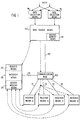
- the inventors were successful in a conscious effort to develop a data communication system having the above-desired requirements, while at the same time, being implementable on the majority of data communication hardware devices which are in existence today, i.e., the data communication system of the present invention is hardware or platform independent and, therefore, can be implemented on the vast majority of existing hardware installations by an appropriate change in the system programming. Since the data communication system of the present invention is platform independent, the important aspects of the invention will be generically described with appropriate references to exemplary hardware devices when they are known. Whenever appropriate, reference will be made to FIGS. 1-9 illustrating block and flow chart diagrams of the preferred embodiment of the present invention.
- multicast is defined as the sending of information from one-source-to-many, but not necessarily all, receiver devices connected to a communications network.
- multicast One inherent requirement in utilizing a "multicast” data delivery approach is that data must be able to be collected at a single or small number of data sources from which all data is to be transmitted.
- the delivery of data from a single source is preferred and advantageous in that a single data source means 100 is able to maintain control (i.e., does not have to share the transmission time or bandwidth) of the data communication network.
- unnecessary data delay is introduced as the respective sources fight for control of the communication network (via handshaking, etc.) before transmitting their data onto the communications network.
- data collection means 98 and 99 which collect relevant data, and supply the data to the single data source means 100. It should be understood that the data collection means 98 and 99 could each represent any well known data collection devices, for example, IBM PCs with appropriate communication facilities.
- a second feature of the present invention which allows swift data delivery to an unlimited number of remote receivers while introducing minimum data delay, concerns a unique approach to the job of providing selected data to each of the respective receivers. Rather than having a single central device which performs all of the data management and selective channeling routines and which results in cumulative data delays, the present invention uses an approach whereby all available data is transmitted to all of the receivers on a communication network, and each of the respective receivers is delegated the task of selecting out the data it needs.
- the selecting-at-the-point-of-receipt approach is advantageous, in that none of the receivers experiences data delay caused by other devices receiving data on the data communication system. Instead, only slight data delay is introduced at the point of receipt as each receiver makes a copy of all the data available along the communication network and then performs respective selecting functions to select out the particular data that it needs.
- the present invention also provides for a data guarantee.
- a tremendous number of conditions can interrupt data delivery to any of the receivers, for example, an interrupted link in the communication system can isolate one or more of the respective receivers.
- another design goal of the present invention is to provide a data communication system which includes facilities whereby each receiver can determine whether all data has been received.
- the present invention utilizes a data packet sequencing and monitoring routine.
- the discussion of this routine begins with important functions which are performed at the point of data transmission.
- each respective data packet is packaged to contain data representing data packet sequencing data in addition to data corresponding to an information field.
- the data packet sequencing data can be of any type of data (e.g., time stamp, consecutive sequence numbers, etc.), as long as it can be used by a remote device to track consecutive data packets to see whether the data packets as a whole represent a complete data packet sequence.
- the data packet sequencing data would correspond to consecutive data packet sequencing numbers (e.g., data packet 0000, data packet 0001, etc).
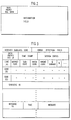
- FIG. 2 is a block diagram illustration of the most fundamental data packet containing only data packet sequencing data and an information field.
- the block diagram of FIG. 3 illustrates examples of other useful data (to be described below) which can be packaged into a data packet.
- each receiver includes a failure detection means (903; FIG.9) which continually monitors incoming data packet sequencing data to check whether all consecutive data packets in the sequence have been received (see the flowchart of FIG. 5B). If a data packet is received without the next consecutive sequencing data, the respective receiver immediately knows that there has been a failure in reliable data receipt. In an example utilizing the preferred consecutive data packet sequencing numbers, if a receiver receives a data packet with an advanced sequencing number, rather than the expected next consecutive sequence number, the receiver will immediately know that data has not been received.
- the sending-data-packets-only-when-full approach is disadvantageous in a first respect, in that, data in a partially full data packet may become dated (e.g., stock pricing and/or availability may change) if an excessive amount of time occurs before transmission.
- the approach is disadvantageous in a second respect, in that, if a communication link failure were to occur to isolate a respective receiver, that receiver may continue to operate under the assumption that it has received the most recent data packet in the sequence, and the lack of incoming data packets is due to the lack of data activity. This potential is unacceptable in many applications where the prompt determination of a data-source-to-receiver communication failure is critical (e.g., radar applications).
- the present invention further incorporates a data packet "heartbeat" approach.
- the data communications system is given a "heartbeat” or “pulse” which represents the minimum frequency at which data packets will be sent.
- a “heartbeat” or “pulse” which represents the minimum frequency at which data packets will be sent.
- non-full data packets are also transmitted at every occurrence of a “reference” interval of time (S-404). Note that, as data packets may become full at a much greater frequency than the "reference" interval of time, the "heartbeat” or “pulse” represents a minimum frequency at which the data packets will be sent.
- the data packet transmission function of the data source means 100 can be summarized and described with reference to the flowchart of FIG. 4.
- the data source means receives data (S-401) and assembles the data into data packets (S-402).
- the data source means 100 continually asks whether the data packet is full (S-403), and if so, the data packet is immediately transmitted (S-405) and a copy is stored in an archive memory means (to be described ahead). If the data packet is not full (S-403), the data source means 100 asks (S-404) whether the elapsed time is equal to a reference interval of time (to be described ahead). If yes, the data packet is immediately transmitted and a copy is stored in an archive memory means (S-405). If no, the data source means continues to perform steps S-401 - S-404.
- the "heartbeat" of the system or the “reference” interval of time can be defined in a number of different ways.
- the "heartbeat” can be defined by a "periodic" interval of time (e.g., like a periodic clock), whereby respective data packets are sent at at least every occurrence of the "periodic" interval of time.
- the respective receivers At the receiving end, the respective receivers expect the receipt of respective data packets at every occurrence of this "periodic" interval of time.
- FIGS. 5A-B are flow chart illustrations showing the basic data packet reception and failure detection functions, i.e., the functions performed by the respective receiver means A-D.
- This first possible definition of the "heartbeat” is disadvantageous, in that there is a possibility that the data communication system might be transmitting more data packets than are actually needed to provide a data guarantee. More specifically, situations may occur where data packets become full and are transmitted at times which are immediately prior to the periodic interval of time. If a "periodic" data packet is sent immediately thereafter, despite providing the “heartbeat” function, the "periodic" data packet in these situations represent a waste as the data packet may contain zero data, and the respective receivers have just received an indication that the communications system was OK (i.e., the immediately preceding data packet).
- a second definition of the system's heartbeat represents the preferred approach.
- the "heartbeat” is defined at the occurrence of a "predetermined” or “elapsed” interval of time, as measured from the transmission of the immediately preceding data packet.
- every transmission of a respective data packet begins the "heartbeat" clock running anew. Even if a respective data packet is not full, the data packet is transmitted if a "predetermined” amount of time has elapsed since the transmission of the immediately preceding data packet. (See S-404; FIG. 4).
- each respective receiver utilizes the receipt of a data packet as a reference with which to measure time in monitoring for the receipt of the next preceding data packet, i.e., the next data packet should be received before or at the lapse of the "predetermined" interval of time. (See FIG. 5.)
- the measurement of "elapsed" time since receipt of the immediately preceding data packet represents the preferred approach.
- the "heartbeat" of the system can be made adjustable by having each data packet contain data corresponding to the value of the current "heartbeat" value or maximum amount of time which should occur before the next data packet is received.
- the immediately above advantages provide insight into the determination of an appropriate interval of time.
- the value chosen for the "reference” time parameter should not exceed a maximum “ripened data time”, which represents the maximum time within which data should be transmitted by the data source before it becomes valueless and outdated.
- a maximum “ripened data time” represents the maximum time within which data should be transmitted by the data source before it becomes valueless and outdated.
- a stock trading house might demand less than a second data delay while a point-of-sale inventory data base change distribution might tolerate a 30 second delay, and in contrast to the above two times, a radar application might demand less than a 30 millisecond data delay.
- the present invention is also advantageous in that, the use of a "heartbeat" additionally provides a means whereby receivers can also monitor for the occurrence of a major system failure. If a respective receiver continues to operate without the receipt of data packets for an extended period of time, at some point, an assumption can be made that there has been a critical failure in the data communication system. In order to implement this additional "system failure” function, a predetermination must be made as to an appropriate "system failure detection time”, i.e., the amount of time after which a receiver will assume that there has been an ongoing and critical failure in the data communication system. A critical difference which affects the determination of the "system failure detection time” as opposed to the "reference" interval of time (for defining the heartbeat) should be pointed out.
- the "heartbeat” or “reference” time value is a global time parameter which is universally applied throughout the entire communication system.
- the "system failure detection time” value is a local time parameter which is applied at any one of the respective receiver installations. This can be further explained as follows. While the data communication system requires that the “heartbeat” be universal such that each of the respective receivers can monitor for respective data failure problems, there is no need for a universal "system failure detection time.” As a result, a different "system failure detection time” can be set for each of the respective receivers.
- system failure detection time In determining an appropriate "system failure detection time", it should be noted that different receivers within the same data communication system may have widely varying requirements. As an example, one stock trading company might demand to know of a critical system failure within 30 seconds, while a different stock trading company might be willing to tolerate 10 minutes. As a general rule, The "system failure detection time” should attempt to give the data communication system a reasonable length of time within which to recover, while at the same time, the length of time should not exceed a maximum time after which there is a possibility that the continued operation of the receiver will result in damaging results.
- Data is collected by data collection means 98 and 99 and is forwarded to data source means 100 (S-401).
- the data source means 100 assembles the data into respective data packets (S-402), each having data corresponding to a data packet sequencing number and an information field.
- data packets are transmitted from the data source means 100 anytime a respective data packet becomes full (S-403, 405), or if not full, at the occurrence of a predetermined interval of time (S-404, 405).
- each of the communication links 102, 110-114 represent any well known communication link, for example, discrete wire connections, electromagnetic transmission, infrared, satellite transmission, etc.
- the communication node 104 represents any well known node device which will provide the necessary connection and transition between the communication link 102 and the respective communication links 110-114.
- the communication node 104 can be a gateway injector which is part of a Local Area Network (LAN) which encompasses the communication node 104 and the communication links 110-114.
- LAN Local Area Network
- each of the receiver means A-D continually monitors the data communication network (S-501) for a data packet, and continually asks whether a data packet has been received (S-502). If a data packet has not been received, the receiver asks (S-504) whether time is in excess of the reference interval of time. If not, the reception function is returned to a step S-501. If time is in excess of the reference interest of time (S-504), the receiver asks whether time is in excess of the "system failure detection time" (S-505). If yes, the receiver flags a critical failure in the data communication system (S-507). If time is not in excess of the system failure detection time, the receiver flags (S-506) a failure in the reliable receipt of a data packet returns to the step of S-501.
- the receiver inserts (S-503) the data packet into a ring buffer (to be described ahead), and then asks (S-508) whether the data packet sequence data is equal to :1) the data packet sequence data of a data packet recovery request; or, 2) the next consecutive data packet sequence data in the sequence. If yes, the receiver returns to the step S-501. Alternately, if the answer is no, the receiver flags (S-506) a failure in the reliable receipt of a data packet, before returning to a step S-501.
- FIG. 5C is a flowchart portion illustrating a data packet recovery request step which can be substituted into the dashed portion 540 of FIG. 5B, such that a receiver can issue a data packet recovery request (S-541) after there has been a failure indicated in the reliable receipt of a data packet (S-506).
- S-541 data packet recovery request
- S-506 data packet recovery request
- the present invention incorporates an independent data recovery means or file server means 120 and limits communication with the data source means.
- data recovery means 120 it is useful to first describe the limitations which are imposed on the communication between devices in the system.
- FIG. 1 Shown in FIG. 1 are dashed “session” lines which represent logical paths where communication sessions can be conducted between respective devices within the system.
- the dashed “session” lines are illustrated with arrows which indicate whether the communication path is unidirectional (i.e., one-way) or bidirectional (i.e., two-way).
- the logical session lines do not necessarily represent actual physical lines, as all of the communication functions can performed using the existing communication network 102, 104, 110-114, or any other well known communication scheme (e.g., infrared, satellite transmission, etc.)
- the receivers A-D can only receive direct communication sessions from the data source means (i.e., unidirectional), and cannot directly communicate with the data source means 100 to request a recovery function. Instead, the receivers A-D must use an appropriate "session” line to direct a recovery request to the recovery means 120. As a result, the preferred embodiment avoids the data source operating time disadvantages mentioned above.
- the recovery means In a manner similar to the receiver means A-D, the recovery means continually monitors the data communications network 102, 104, 110-114 for the availability of data packets. (Unless otherwise indicated, the recovery means 120 operates with the same data packet reception and failure detection function as illustrated in FIGS. 5A-B).
- the recovery means 120 Upon receipt of a data packet, the recovery means 120 stores a copy in a server memory means 124 which has sufficient memory storage space for storing a number of the most current data packets which have been received.
- a server memory means 124 Any well known memory device can serve as the server memory means 124, for example, in a preferred embodiment, the server memory means 124 would represent a ring buffer. It should be noted that, within memory device limitations, the ring buffer can selected to be any size, to store any number of the most recent data packets. If the ring buffer provided is of sufficient size to store a large number of data packets, chances are that the recovery means 120 will be able to perform the recovery function without disturbing the operation of the data source means 100.
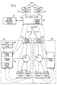
- the recovery or file server means 120 In performing its recovery function (see FIG. 6), the recovery or file server means 120 continually monitors (S-601) the respective session lines from the receiver means A-D to see (S-602) whether there has been a data packet recovery request.
- the present invention described thus far is particularly advantageous in terms of providing an immediate determination as to the information to be contained in the data packet recovery request. If a respective receiver performs its data packet sequence monitoring and failure detection functions and makes a determination that a data packet sequence number has been missed, the receiver can conveniently request recovery of that particular data packet, i.e., by specifying the missed data packet sequence number in the data packet recovery request. Thus, in effect, further delay beyond a receiver's data packet monitoring function is avoided, and the affected receiver can issue an immediate recovery request.
- the recovery means 120 If the recovery means 120 receives a request for a particular data packet, it will extract the data packet sequence data from the request (S-603) and attempt to obtain a copy of the data packet from the server memory means 124 to satisfy the request (S-607). If a copy of the requested data packet is contained in the server memory means 124, a copy is obtained and is sent (S-611) to the requesting receiver either through the existing data communication network 104, 110-114, through the bidirectional "session" line, or through any other well known data communication or rebroadcast scheme. Whichever method is used to satisfy the request, care must be taken such that there is no interference between the data packet recovery and the normal data packet transmissions on the data communication system.
- the above use of the server memory means 124 to provide copies of requested data packets may not be enough. If the memory size of the server memory means 124 is small and/or a large amount of time is allowed to pass before attempting to satisfy a request, the server memory means 124 may no longer contain the requested data packet, i.e., the copy of the requested data packet may have been dumped from the server memory means 124 to make room for a more recent data packet. Furthermore, as the recovery means 120 receives the copies of the data packets from the communication network 102, 104, 110-114, there exists a possibility that the recovery means 120 might also experience a failure in the reliable receipt of a data packet. In such a case, the recovery means 120 as described thus far would not be able to satisfy a request for the data packet which has been missed.
- the preferred embodiment of the recovery means 120 also contains request means 122.
- the request means 122 Upon a determination that a copy of the requested data packet cannot be obtained from the server memory means 124 or has been missed, the request means 122 issues a request to obtain a copy from an alternative device (S-608).
- the alternative device can be any other device in the system, as long as the alternative device normally retains copies of the data packets.
- a request via an appropriate "session” lines may be issued to any of the receiver means A-D which normally retains copies of the data packets.
- the alternative copy of the requested data packet can then be returned to the recovery means 120 through the use of the "session" lines, the communication network 104, 110-114, or any other well known communication method.
- the advantage of this approach is that, the data source means 100 is still not involved in the recovery operation, and therefore, all of the data source operating time and communication network bandwidth can be dedicated to normal transmission of data packets.
- this approach is disadvantaged in that, there is a possibility that the alternative device also might not have a copy of the requested data packet, resulting in a need for a further request, and therefore, data delay.
- a request via an appropriate "session” line may be issued to the data source means 100.
- the data source means 100 In order for the data source means 100 to be able to perform the recovery function in addition to transmitting data packets, the data source means 100 also stores a copy of every data packet transmitted in an archive memory means 101. This approach is advantageous in that, there is certainty that the data source means will always contain a copy of the data packet which has been requested.
- the recovery means After determining (S-607) that a requested data packet is not available via the server memory means, the recovery means attempts (S-608) to obtain a copy of the requested data packet from another device (i.e., one of receivers A-D). This, in effect, is an attempt to first obtain a copy of the requested data packet without disturbing the operation of the data source means 100. This step can be repeated any number of times with a number of default devices in an attempt to obtain a copy from an alternative device. If the attempt is successful (S-609), the recovery means 120 performs the local recovery (S-611) and returns to a step S-601. Alternatively, if the recovery means is unable (S-609) to obtain a copy from an alternative device, the recovery means issues (S-610) a recovery request to the data source means 100 which is sure to have a copy of the data packet.
- the data source means In performing a data packet recovery function, the data source means follows the basic operations illustrated in the flowchart of FIG. 7. In essence, the data source means 100 continually monitors (S-701) the "session" line for a data packet recovery request, and upon receipt of such a request (S-702), a copy of the requested data packet is obtained from the archive memory means 101 (S-703).
- the disadvantage of the data source recovery approach provides insight into the appropriate data communication path which the data source means should use to satisfy the recovery request. If the data source means satisfies the request by retransmitting the data packet using the data communication network 102, 104, 110-114, the approach is disadvantageous in that, important communication medium resources (i.e., transmission bandwidth or transmission time) are being absorbed by the use of the communications medium to retransmit requested data packets. Rather than being able to devote a maximum amount of the communication medium resources to support a continuous transmission of updated data, a percentage must be dedicated to the recovery routine. As the number of data packet recovery requests to the data source means 100 increases, more and more of the communication medium is used, resulting in a proportional increase in data delay.
- important communication medium resources i.e., transmission bandwidth or transmission time
- the use of the data communication network 102, 104, 110-114 should normally be avoided in satisfying a data packet recovery request.
- the data source means 100 should perform a "local" recovery (S-705) by transmitting a copy of the requested data packet to the requesting recovery means 120 via the use of the "session" communication link, or any other well known alternative communication method.
- the recovery means 120 could also monitor the number of requests it has received for the same data packet (S-604). If the number of requests exceeds a predetermined number and a request for that particular data packet has not been recently sent (S-605), the recovery means 120 sends the data source means 100 a "global" data packet recovery request (S-706). Although a little data communication resources (i.e., operating time or bandwidth) is consumed in the recovery operation, this approach is advantageous in that, data packet recovery by all of the receivers is almost instantaneous.
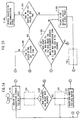
- FIGS. 8 and 9 structural elements which are the same as those in FIGS. 1-7 are designated by the same reference numerals or characters, and detailed descriptions thereof are omitted.
- the operation of the data collection means 98, 99 and the data source means 100 is the same as was described with reference to FIG. 1.
- the data source means conducts transmission of the updated data packets using the wide area distribution device 850 emitting wide area transmissions 851, 852.
- the wide area distribution device 850 and wide area transmissions 851, 852 can represent any well known wide area distribution method, for example, FM sideband transmissions, microwave transmissions, token ring distributions, and satellite transmissions.
- the wide area transmissions of the data packets are received by the local area network 800 and local area network 860, through the use of the gateway injector means 810 and 870, respectively.
- the local area network 800 could easily represent a local data communication network in New York
- the local area network 860 could easily represent a local data communication network in London.
- the main purpose of the gateway injector means 810 is to receive transmission of data packets from the data source means, and provide the required transition between the wide area communication link and a local area network.
- the gateway injector means 810 is to provide the processing of data packets such that they can make the transition between the medium of the wide area transmission 851 and the token ring medium 801 of the local area network 800.
- the gateway injector means 810 can represent any well known device having the ability to provide the transition of data packets from one medium to another.
- the nature of the gateway injector means 810 would be such that, any communication which is conducted between the gateway injector means 810 and the token ring 801 follows the protocol of the IEEE 802.2 and 802.5 standards.
- FIG. 9 there are shown a data packet 104 which is arriving at the gateway injector means from the wide area transmission 851, and a data packet 103 which has been processed and injected onto the token ring 801 by the gateway injector means 810.
- token ring systems can be used to allow the data communication system to have multiple data packet streams which are directed only to specific groups of receivers, i.e., the token ring systems already have a built-in "functional addressing" ability which allows the user to program devices along the token ring such that they will only accept certain classes of data packets.
- the token ring systems already have a built-in "functional addressing" ability which allows the user to program devices along the token ring such that they will only accept certain classes of data packets.
- the user can program the respective devices along the token ring to accept any of twelve (12) different classes of data packets. (Note that this situation provides an illustration of the "multicast" operation of the present invention, i.e., the transmission of data from one-source-to-many, but not necessarily all receiver devices connected to a communications network.)
- FIG. 9 provides further illustrations as to the preferred operations and construction of a typical receiver or workstation means 820.
- the receiver means 820 contains a receiver adapter means 900.
- the receiver adapter means 900 contains a data packet catcher means 901 which can represent any well known device providing connection to the token ring 801, for example, any processor such as an IBM PC performing the steps S-501, 502 in FIG. 5A.
- the nature of the data packet catcher means 901 would be such that, any communication which is conducted between the receiver means 820 and the token ring 801 follows the protocol of the IEEE 802.2 and 802.5 standards.
- the data packet catcher means 901 can be designed to provide a number of important functions.
- the catcher means 901 should be designed to continually monitor the token ring 801 for the availability of a data packet (S-501). If a data packet is available, the data packet catcher means should immediately make a copy and provide it to the failure detection or "negative acknowledgement" (NACK) means 903.
- the purpose of the failure detection means 903 is to check for failure in the reliable receipt of consecutive data packets (FIG. 5B) by monitoring the data packet sequencing data (S-508) and for the receipt of a respective data packet at at least a minimum frequency defined by the "reference" interval of time (S-504). If the failure detection means 903 determines that there has been a failure in the reliable receipt of a data packet (S-506), the failure detection means 903 can issue a local data packet recovery request (S-541).
- Another important function, which the data packet catcher means 901 can provide, is to conduct an operation which provides a further check as to data guarantee. Even though a respective receiver may appear at first sight to receive the transmission of every data packet, the data within a respective data packet may have been corrupted, e.g., an individual data bit within the packet may have been changed by a burst of noise.
- the further method steps of FIG. 5D can be substituted for the blocked portion 520 in FIG. 5A.
- the data packet catcher means 901 can ask whether a check of the data using the error detection field (FIG. 3) reveals that the received data has been corrupted.
- a preferred embodiment of the present invention would utilize a token ring system which has the facility to perform a 32-bit cyclic redundancy check using the error detection field.
- the receiver discards the corrupted data packet (S-522). Alternatively, if the data has not been corrupted, the receiver maintains the data packet (S-523).
- the receiver adapter means 900 can also include a communication means 902 which can be used to provide, conduct and monitor the "sessions" which are conducted with the recovery means 830.
- This function would mainly include, but would not be limited to, "sessions” used to send a data packet recovery request to the recovery means which functions in the manner described in FIG. 6.
- the communication means 902 could monitor for and answer requests for receiver health reports (to be described ahead).
- the ring buffer device is a data memory device which has sufficient memory storage area to store a number of the data packets which have been recently received, for example, the ring buffer 904 might be able to store the latest 50 data packets.
- the data packets may be stored in the order of data packet sequence number, or strictly in the order of receipt. If the data packets are stored in the data packet sequence order and a respective data packet is missed, the operation of the data packet catcher means 901 and the failure detection means 903 (as functionally described in FIG. 5B) can be programmed to reserve memory space in the ring buffer means 904 until a recovery data packet is received.
- the data communication system of the present invention provides a continuous stream of data packets and the memory space in the ring buffer means 904 is limited, it should be remembered that the copy of a respective data packet in the ring buffer is only available for a limited amount of time. Furthermore, it should be remembered that the data stored in the ring buffer is a pile of unsorted and raw data representing all available data from the data source means 100. As a result of the foregoing, it can be seen that the receiver means 820 has a further need for a means to access the needed data from the ring buffer while it is still available.
- the preferred receiver means embodiment of the present invention further includes data management means 905 (e.g., a data base management system), and data table storage means 910 which contains the selected data in a table.
- the data management means 905 should be of a construction or programming which allows it to access the data in the ring buffer means 904, and extract all the data which is needed to perform the receivers intended function.
- the data management means 905 can use the accessed data to update the table of data which is stored in the data table means 910.
- the data stored and maintained in the data table means 910 can be arranged in any convenient order, e.g., numerically, alphabetically, etc.
- the data accessing and selecting function may introduce some data delay, i.e., excessive data delay is introduced before the data is available at the updated data table 910.
- the data accessing and selecting function may introduce some data delay, i.e., excessive data delay is introduced before the data is available at the updated data table 910.
- a data processing means 911 can be included to use the updated data from the data table means to perform the receiver means intended function. Rather than having the data processing means continually perform its intended function, note that an embodiment is envisioned wherein the data processing means 911 remains idle unless and until it receives a signal from the data table means that some data of interest has changed.
- the receiver's data management means or data table means can include a change assessment program which can be used to trigger the running of a program which then utilizes the changed data in satisfying the functional objectives of the receiver.
- the running of the program can be triggered every time data is changed, or in another embodiment, can be triggered after the data changes which have occurred becomes greater than a predetermined threshold value (i.e., after a certain number of data changes has occurred, or, after the value of the data change is greater than a predetermined value).
- the data packet of FIG. 3 is utilized to illustrate one example of a number of uses which can be made of extra information space.
- FIG. 3 In the first row of FIG. 3 there is shown a "receiver subclass code” which allows the segregation of multiple streams of data packets to different groups of receivers. Use of this approach is particularly attractive in applications where there are large groups of receivers which have only an interest in a subset of the data. This would serve to avoid unnecessary data manipulation, and hence, additional data delay.
- the flowchart portion of FIG. 5E can be substituted for the dashed portion 530 in FIG. 5A.
- the receiver will ask whether the "receiver subclass code" matches a valid code to be received. If yes, the receiver continues with the step S-503. If not, the receiver ignores the data packet and returns to the step S-501.
- the time stamp which typically is the time at which the data packet is sent, provides useful time information which can be used for a number of different purposes. For example, the time information is useful in helping a respective receiver determine the relative length of the data delay which has been introduced as the data packet travels through the data communication system.
- time stamps In addition to the time stamp associated with the data packet, another time stamp can be associated with each data field. These time stamps provide a way to order the data fields chronologically on the basis of the time of data field creation.
- the system status data provides useful information as to the current status of the data communication system.
- extra information space in a data packet can also be used by the data source means to sent a personal message to any of the respective receivers.
- a good use of a personal message would be a request for the receiver means to report its current status back to a central network management facility 97.
- each of the receiver means has the ability using a communication means 902 to route an answer back to the data source means 100 using the previously described "session" lines or rebroadcast on the local network to a local health facility 840 which reports the collective receivers' status to a central network management information focal point which executes a network management program, e.g., the IBM Netview program.
- the data source means 100 can first send an individual message query to each of the respective receiver installations. After a reasonable length of time has been given for all of the receivers to answer the request, the data source means can use the system status block to report the status throughout the system.
- the first block entitled “message ID" can be a unique set of numbers or characters such that a personal message can be directed to a respective receiver.
- the second block contains the time of the message, while the last block contains the message itself.
- a message can be sent between any two or more devices in the data communication system. If a message is initiated by any other device than the data source means, the request is forwarded to the data source means by having the message follow the appropriate communication path along the "session" lines. Receipt and transmission of message information is typically managed at each of the respective receivers by a communication means 902.
Claims (19)
- Système de répartition de données à grande performance, fiable, comprenant:
un seul moyen de source de données (100) pour assembler des données en paquets de données et transmettre lesdits paquets de données respectifs lorsqu'ils deviennent pleins, ou lorsqu'ils ne sont pas pleins, à l'apparition d'un intervalle de temps de référence, chacun desdits paquets de données ayant des données correspondant aux données de mise en séquence de paquets de données et à un champ d'informations;
une pluralité de moyens récepteurs (A, B, C, D; 820, 821, 900) pour recevoir lesdits paquets de données transmis, chacun desdits moyens récepteurs étant capable de sélectionner des paquets de données spécifiques, et chacun desdits moyens récepteurs ayant un moyen de détection de défaillance pour vérifier toutes défaillances dans la réception fiable desdits paquets de données en supervisant:
lesdites données de mise en séquence de paquets de données; et
la réception d'un paquet de données respectif à au moins une fréquence minimale définie par ledit intervalle de temps de référence;
ce qui fait que la réception d'un paquet de données ayant des données de mise en séquence de paquets de données qui ne coïncident pas avec des données de mise en séquence de paquets de données voulues suivantes d'une séquence prédéterminée, ainsi que le fait de ne pas recevoir un paquet de données respectif dans une expiration de période de temps correspondant audit intervalle de temps de référence, indiquent une défaillance de réception fiable desdits paquets de données. - Système de répartition de données selon la revendication 1, dans lequel ledit temps de référence correspond à un laps de temps de quantité prédéterminée qui est mesuré à partir d'une transmission d'un paquet de données précédent.
- Système de répartition de données selon les revendications 1 ou 2, dans lequel
chacun desdits moyens récepteurs peut émettre une demande de paquet de données, ledit système de répartition comprenant en outre:
un moyen de récupération pour fournir un paquet de données demandé au moyen récepteur respectif qui émet une demande pour ledit paquet de données demandé en réponse à une détermination qu'il y a eu défaillance dans une réception fiable d'un paquet de données. - Système de répartition de données selon la revendication 3, dans lequel lesdites données de mise en séquence de paquets de données correspondent à un numéro de mise en séquence de paquets de données.
- Système de répartition de données selon la revendication 4, dans lequel ledit moyen récepteur respectif identifie un paquet de données respectif demandé en utilisant ledit numéro de mise en séquence de paquets de données.
- Système de répartition de données selon l'une quelconque des revendications 3, 4 ou 5, dans lequel ledit moyen de récupération comprend:
un moyen de mémoire de serveur pour recevoir lesdits paquets de données, et pour emmagasiner des copies d'un nombre prédéterminé de la plupart des paquets de données en cours qui ont été transmis; et
un moyen de demande capable de communiquer avec ledit moyen de source de données pour demander la retransmission d'un paquet de données particulier à partir dudit moyen de source de données au cas où ledit moyen de récupération ne puisse pas satisfaire une demande par le récepteur respectif d'un paquet de données particulier provenant dudit moyen de mémoire de serveur, ou au cas où plus d'un nombre prédéterminé de recepteurs respectifs émettent une demande d'un même paquet de données particulier. - Système de répartition de données selon la revendication 1, ou l'une des revendications 2-6, dans lequel chacun desdits paquets de données a en outre des données correspondant aux données de vérification d'erreur, et dans lequel ledit moyen récepteur accomplit une autre vérification de la réception fiable desdits paquets de données utilisant lesdites données de vérification d'erreur.
- Système de répartition de données selon la revendication 1, ou l'une des revendications 2-7, dans lequel ledit moyen récepteur comprend en outre:
un moyen tampon pour emmagasiner lesdits paquets de données reçus à partir dudit moyen de source de données. - Système de répartition de données selon les revendication 7 ou 8, dans lequel ledit moyen récepteur comprend en outre:
un moyen de gestion de données pour avoir sélectivement accès aux données dans lesdits paquets de données emmagasinés dans ledit moyen tampon. - Système de répartition de données selon la revendication 9, dans lequel ledit moyen récepteur comprend en outre:
un moyen de traitement de données pour le traitement et l'accomplissement d'opérations prédéterminées utilisant lesdites données sélectionnées, et un moyen pour déclencher lesdits traitement et accomplissement lors d'une détection de données d'un type prédéterminé. - Système de répartition de données selon la revendication 1, ou l'une quelconque des revendications précédentes 2-10, dans lequel chacun desdits paquets de données a des données correspondant aux données de tampon horaire.
- Système de répartition de données selon la revendication 1, ou l'une quelconque des revendications précédentes 2-11, dans lequel ledit champ d'informations d'un paquet de données respectif a une pluralité d'éléments de données, chacun desdits éléments de données étant constitué de données correspondant à un champ de code et à un champ d'informations correspondant.
- Système de répartition de données selon la revendication 1, ou l'une quelconque des revendications précédentes 2-12, dans lequel chacun desdits paquets de données contient un code de sous-classement de récepteur pour permettre une pluralité de débits de paquets indépendants.
- Système de répartition de données à grande performance, fiable, comprenant:
un réseau de communications interconnectant un moyen de source de données avec un moyen serveur de fichiers, et une pluralité de moyens récepteurs;
ledit moyen de source de données émettant périodiquement des paquets d'informations audit moyen serveur de fichiers et à ladite pluralité de moyens récepteurs;
chacun desdits paquets comprenant un numéro de séquence de paquets, un tampon horaire, et une pluralité de champs d'informations, chaque champ d'informations comprenant un champ de code unique et un champ de données correspondant;
un tampon d'anneau (904) dans chaque moyen respectif des moyens récepteurs de ladite pluralité de moyens récepteurs pour emmagasiner une pluralité de paquets reçus sur ledit réseau de communications;
un moyen de gestion de données (905) pour remplir une fonction de sélection de code dans chacun desdits moyens récepteurs pour sélectionner dans ladite pluralité de champs d'informations de chaque paquet emmagasiné dans ledit tampon d'anneau, les champs de données correspondant aux codes sélectionnés desdits codes uniques;
un moyen de table de données ordonnées (910) dans chacun desdits moyens récepteurs pour emmagasiner dans une séquence ordonnée lesdites données sélectionnées provenant de l'accomplissement de ladite fonction de sélection de code;
un moyen de traitement de données (911) dans chaque moyen récepteur pour utiliser lesdites données sélectionnées dans ledit moyen de table de données ordonnées;
ledit moyen serveur de fichiers emmagasinant tous lesdits paquets reçus à partir dudit réseau de communications;
un moyen d'accusé de réception négatif dans chacun desdits moyens récepteurs pour anticiper la réception desdits paquets périodiques provenant dudit moyen de source de données et détecter l'omission d'une réception anticipée d'un paquet de données et, en réponse à cela, engendrer une demande de retransmission audit moyen serveur de fichiers qui accomplit la retransmission soit par une émission soit par une connexion du type à session;
ce qui fait qu'il est établi une communication de données fiable, à haute performance depuis ladite source de données jusqu'audit moyen récepteur. - Système de répartition de données selon la revendication 14, dan lequel ledit moyen serveur de fichiers remplit une fonction d'évaluation d'accusé de réception négatif si les accusés de réception négatifs provenant d'une sous-pluralité de ladite pluralité de moyens récepteurs sont susceptibles d'indiquer une défaillance d'émission d'un paquet depuis ledit moyen de source de données jusqu'audit moyen récepteur; et
dans lequel ledit moyen serveur de fichiers comprend en outre un moyen de demande pour établir une session de communications entre ledit moyen serveur de fichiers et ledit moyen de source de données en réponse à une indication provenant de ladite fonction d'évaluation d'accusé de réception négatif, pour avoir accès à un paquet d'informations à partir dudit moyen de source de données correspondant à ladite émission défaillante. - Système de répartition de données selon les revendications 14 ou 15, dans lequel ledit moyen de gestion de données remplit une fonction d'évaluation de changement pour avoir accès aux données emmagasinées dans ledit moyen de table de données ordonnées, et déterminer si des changements de valeur desdites données correspondant à un code sélectionné, sont supérieurs à une valeur de seuil prédéterminée;
ledit moyen de table de données ordonnées étant sensible à ladite fonction d'évaluation de changement pour sortir de nouvelles valeurs de données identifiées comme dépassant ledit seuil; et
ledit moyen de traitement de données étant sensible à une sortie provenant dudit moyen de table de données ordonnées pour exécuter des tâches correspondant auxdites données changées qui ont dépassé ladite valeur de seuil. - Système de répartition de données selon les revendications 14, 15 ou 16, comprenant en outre:
ladite émission périodique desdits paquets de données par ledit moyen de source de données étant basée sur un intervalle de temps de référence dans lequel il est demandé d'émettre un paquet de données suivant à la fin dudit intervalle de temps de référence mesuré à partir de l'émission du paquet de données le plus récent;
ce qui fait que ladite source de données ne manque pas d'émettre un paquet de données moins fréquemment qu'une fois pour chacun desdits intervalles de temps de référence. - Système de répartition de données selon la revendication 14, ou l'une des revendications 15-17, dans lequel ledit réseau de communications comprend un réseau local avec bus annulaire à jeton.
- Système de répartition de données selon la revendication 14, ou l'une des revendications 15-18, dans lequel ledit moyen d'accusé de réception négatif du moyen récepteur respectif émet ladite demande de retransmission en réponse à une détection de l'expiration d'un intervalle de référence mesuré à partir de la réception du paquet le plus récent, ou en réponse à une détermination d'un numéro de séquence de paquets manquants, ou en réponse à l'absence d'un paquet périodique anticipé qui n'a pas été reçu à partir dudit moyen de source de données.
Applications Claiming Priority (2)
| Application Number | Priority Date | Filing Date | Title |
|---|---|---|---|
| US87850 | 1987-08-21 | ||
| US07/087,850 US4807224A (en) | 1987-08-21 | 1987-08-21 | Multicast data distribution system and method |
Publications (3)
| Publication Number | Publication Date |
|---|---|
| EP0303830A2 EP0303830A2 (fr) | 1989-02-22 |
| EP0303830A3 EP0303830A3 (fr) | 1991-02-06 |
| EP0303830B1 true EP0303830B1 (fr) | 1994-02-02 |
Family
ID=22207620
Family Applications (1)
| Application Number | Title | Priority Date | Filing Date |
|---|---|---|---|
| EP88111425A Expired - Lifetime EP0303830B1 (fr) | 1987-08-21 | 1988-07-15 | Système de répartition de données à récepteurs multiples |
Country Status (4)
| Country | Link |
|---|---|
| US (1) | US4807224A (fr) |
| EP (1) | EP0303830B1 (fr) |
| JP (1) | JPS6471233A (fr) |
| DE (1) | DE3887595T2 (fr) |
Families Citing this family (157)
| Publication number | Priority date | Publication date | Assignee | Title |
|---|---|---|---|---|
| JPS63292257A (ja) * | 1987-05-11 | 1988-11-29 | インタ−ナショナル・ビジネス・マシ−ンズ・コ−ポレ−ション | 複数の端末局へのデ−タまたはプログラムのロ−デイング方法 |
| US4947484A (en) * | 1987-11-10 | 1990-08-07 | Echelon Systems Corporation | Protocol for network having a plurality of intelligent cells |
| US4998245A (en) * | 1987-12-17 | 1991-03-05 | Matsushita Electric Industrial Co., Ltd. | Information transmission system having collective data transmission and collection devices |
| DE68923102T2 (de) * | 1988-02-10 | 1995-11-02 | Nec Corp | Kommunikationsverfahren und System mit hohem Durchsatz für eine digitale mobile Station beim Überfahren einer Zonengrenze während einer Verbindung. |
| US5101402A (en) * | 1988-05-24 | 1992-03-31 | Digital Equipment Corporation | Apparatus and method for realtime monitoring of network sessions in a local area network |
| US5109384A (en) * | 1988-11-02 | 1992-04-28 | Tseung Lawrence C N | Guaranteed reliable broadcast network |
| US5036518A (en) * | 1988-11-02 | 1991-07-30 | Tseung Lawrence C N | Guaranteed reliable broadcast network |
| US5124991A (en) * | 1989-03-30 | 1992-06-23 | Photonics Corporation | Error correction for infrared data communication |
| DE68920748T2 (de) * | 1989-08-09 | 1995-06-29 | Alcatel Nv | Sequentielle rückordnung für einen vermittlungsknoten. |
| US5701427A (en) * | 1989-09-19 | 1997-12-23 | Digital Equipment Corp. | Information transfer arrangement for distributed computer system |
| JPH0432940A (ja) * | 1990-05-23 | 1992-02-04 | Toshiba Corp | 分散データベース・システム |
| US5216675A (en) * | 1990-05-23 | 1993-06-01 | The United States Of America As Represented By The Secretary Of The Air Force | Reliable broadcast protocol |
| US5418937A (en) * | 1990-11-30 | 1995-05-23 | Kabushiki Kaisha Toshiba | Master-slave type multi-processing system with multicast and fault detection operations having improved reliability |
| DE69231729T2 (de) * | 1991-01-23 | 2001-10-18 | Sun Microsystems Inc | Verfahren und gerät zur nachrichtenvermittlung zwischen prozessen mit abgegrenztem bereich |
| US5894547A (en) * | 1991-06-27 | 1999-04-13 | International Business Machines Corporation | Virtual route synchronization |
| EP0537903A2 (fr) * | 1991-10-02 | 1993-04-21 | International Business Machines Corporation | Système de contrôle distribué |
| JP2972419B2 (ja) * | 1991-11-27 | 1999-11-08 | 日本電気株式会社 | データベース運用制御方式 |
| US5255268A (en) * | 1992-02-04 | 1993-10-19 | International Business | Data distribution network with improved broadcast feature |
| GB9202666D0 (en) * | 1992-02-07 | 1992-03-25 | Madge Networks Ltd | Communication system |
| NL9200253A (nl) * | 1992-02-12 | 1993-09-01 | Nederland Ptt | Atm policing function met autonome referentietijdstippen. |
| US5243596A (en) * | 1992-03-18 | 1993-09-07 | Fischer & Porter Company | Network architecture suitable for multicasting and resource locking |
| US5539727A (en) * | 1992-04-14 | 1996-07-23 | Kramarczyk; Marian | Method and apparatus for configuring and maintaining token ring networks |
| US5351242A (en) * | 1992-04-14 | 1994-09-27 | Marian Kramarczyk | Method and apparatus for configuring and maintaining token ring networks |
| FR2692093A1 (fr) * | 1992-06-05 | 1993-12-10 | France Telecom | Serveur à haut débit. |
| JPH0695986A (ja) * | 1992-06-19 | 1994-04-08 | Westinghouse Electric Corp <We> | リアルタイムデータ・イメージングネットワークシステム及びその操作方法 |
| IL102843A (en) * | 1992-08-17 | 1996-06-18 | Zisapel Yehuda | Carrier sensing multiple access/collision detection local area networks |
| EP0596651A1 (fr) | 1992-11-02 | 1994-05-11 | National Semiconductor Corporation | Réseau de données avec capacité de communication isochrone |
| USRE39116E1 (en) | 1992-11-02 | 2006-06-06 | Negotiated Data Solutions Llc | Network link detection and generation |
| USRE39395E1 (en) | 1992-11-02 | 2006-11-14 | Negotiated Data Solutions Llc | Data communication network with transfer port, cascade port and/or frame synchronizing signal |
| EP0596648A1 (fr) | 1992-11-02 | 1994-05-11 | National Semiconductor Corporation | Détection de la capacité d'un point final d'un réseau |
| DE69331310T2 (de) * | 1992-11-19 | 2002-08-22 | Ibm | Funktionsverteilung im Paketvermittlungsnetz |
| ATE533112T1 (de) * | 1992-11-27 | 2011-11-15 | Io Res Pty Ltd | Verteiltes datenbanksystem und datenbankempfänger dafür |
| AU673021B2 (en) * | 1992-12-28 | 1996-10-24 | Nec Corporation | Management apparatus for volume-medium correspondence information for use in dual file system |
| US5390326A (en) * | 1993-04-30 | 1995-02-14 | The Foxboro Company | Local area network with fault detection and recovery |
| SE515419C2 (sv) * | 1993-06-15 | 2001-07-30 | Ericsson Telefon Ab L M | Förfarande och anordning för resekvensiering |
| US5553081A (en) * | 1994-04-08 | 1996-09-03 | Echelon Corporation | Apparatus and method for detecting a signal in a communications system |
| US5541927A (en) * | 1994-08-24 | 1996-07-30 | At&T Corp. | Method of multicasting |
| KR100404274B1 (ko) * | 1994-09-30 | 2004-04-30 | 코닌클리케 필립스 일렉트로닉스 엔.브이. | 멀티플랫폼인터프리터를포함한응용프로그램을포함하는대량데이타의표현을수신하는멀티미디어시스템,상기멀티플랫폼인터프리터와상호작용하는플랫폼서브시스템및,그시스템또는서브시스템용대용량메모리 |
| US6128648A (en) * | 1994-11-23 | 2000-10-03 | International Business Machines Corporation | Information handling system and method for maintaining coherency between network servers and mobile terminals |
| US5533018A (en) | 1994-12-21 | 1996-07-02 | National Semiconductor Corporation | Multi-protocol packet framing over an isochronous network |
| US6625652B1 (en) | 1995-01-19 | 2003-09-23 | The Fantastic Corporation | System and method for host list pruning |
| US6873627B1 (en) | 1995-01-19 | 2005-03-29 | The Fantastic Corporation | System and method for sending packets over a computer network |
| US5553083B1 (en) * | 1995-01-19 | 2000-05-16 | Starburst Comm Corp | Method for quickly and reliably transmitting frames of data over communications links |
| US6453438B1 (en) | 1995-01-19 | 2002-09-17 | The Fantastic Corporation | System and method for automatically rescheduling a data transmission to members of a group |
| FR2717973B1 (fr) * | 1995-02-07 | 1997-01-03 | Ibm | Acheminement multi-destinataire fiable sur les arbres recouvrants des réseaux de communication par paquets. |
| GB2302243B (en) * | 1995-06-12 | 2000-03-01 | Comm & Control Electronics Ltd | Communication system message acknowledgement |
| US5822523A (en) | 1996-02-01 | 1998-10-13 | Mpath Interactive, Inc. | Server-group messaging system for interactive applications |
| US5805785A (en) * | 1996-02-27 | 1998-09-08 | International Business Machines Corporation | Method for monitoring and recovery of subsystems in a distributed/clustered system |
| JPH09245007A (ja) * | 1996-03-11 | 1997-09-19 | Toshiba Corp | 情報処理装置及び情報処理方法 |
| US6108689A (en) | 1996-10-11 | 2000-08-22 | International Business Machines Corporation | Method and system for processing messages in a distributed computing environment |
| US5915124A (en) * | 1997-01-03 | 1999-06-22 | Ncr Corporation | Method and apparatus for a first device accessing computer memory and a second device detecting the access and responding by performing sequence of actions |
| US6031818A (en) * | 1997-03-19 | 2000-02-29 | Lucent Technologies Inc. | Error correction system for packet switching networks |
| JPH1155256A (ja) | 1997-08-06 | 1999-02-26 | Fujitsu Ltd | マルチポイント接続における再接続処理方法 |
| AU8697498A (en) | 1997-08-08 | 1999-03-01 | Pics Previews, Inc. | A reconfigurable audiovisual previewing system and method of operation |
| US6553404B2 (en) | 1997-08-08 | 2003-04-22 | Prn Corporation | Digital system |
| US6006206A (en) * | 1997-09-08 | 1999-12-21 | Reuters Limited | Data health monitor for financial information communications networks |
| US6247127B1 (en) * | 1997-12-19 | 2001-06-12 | Entrust Technologies Ltd. | Method and apparatus for providing off-line secure communications |
| US6338090B1 (en) | 1998-03-27 | 2002-01-08 | International Business Machines Corporation | Method and apparatus for selectively using input/output buffers as a retransmit vehicle in an information handling system |
| US6404711B1 (en) | 1998-05-19 | 2002-06-11 | Sony Corporation | System including comparing a separated time stamp to a generated timing signal and controlling a timing signal on the basis of continuity of time stamps |
| CA2270621A1 (fr) * | 1998-06-10 | 1999-12-10 | Lucent Technologies, Inc. | Systeme et methode de diffusion de donnees contenues dans un reseau d'ordinateurs |
| US6289012B1 (en) | 1998-08-03 | 2001-09-11 | Instanton Corporation | High concurrency data download apparatus and method |
| US6959323B1 (en) * | 1998-08-27 | 2005-10-25 | Lucent Technologies Inc. | Scalable atomic multicast |
| US6269080B1 (en) * | 1999-04-13 | 2001-07-31 | Glenayre Electronics, Inc. | Method of multicast file distribution and synchronization |
| JP2000307681A (ja) * | 1999-04-16 | 2000-11-02 | Fujitsu Ltd | 中継装置およびフレームトレース方法 |
| US6335933B1 (en) * | 1999-05-21 | 2002-01-01 | Broadcom Homenetworking, Inc. | Limited automatic repeat request protocol for frame-based communication channels |
| US6320501B1 (en) | 1999-05-25 | 2001-11-20 | Pittway Corporation | Multiple sensor system for alarm determination with device-to-device communications |
| US6574795B1 (en) * | 1999-05-28 | 2003-06-03 | Intel Corporation | Reliable communication of data by supplementing a unidirectional communications protocol |
| US6850987B1 (en) * | 1999-06-01 | 2005-02-01 | Fastforward Networks, Inc. | System for multipoint infrastructure transport in a computer network |
| US6674994B1 (en) | 1999-12-01 | 2004-01-06 | Panamsat Corporation | Pickup and delivery of data files |
| US6564064B1 (en) * | 1999-12-01 | 2003-05-13 | Trimble Navigation Limited | Cellular telephone using pseudolites for determining location |
| US6732189B1 (en) | 2000-03-20 | 2004-05-04 | International Business Machines Corporation | Method and apparatus for fault tolerant tunneling of multicast datagrams |
| US6791981B1 (en) | 2000-03-21 | 2004-09-14 | International Business Machines Corporation | Method and apparatus for building a medium cost, self similar, self organizing multicast routing tree |
| US6735200B1 (en) | 2000-03-21 | 2004-05-11 | International Business Machines Corporation | Method and apparatus for monitoring the availability of nodes in a communications network |
| SE0003217L (sv) * | 2000-09-12 | 2002-03-05 | Kvaser Consultant Ab | Arrangemang för att i distribuerat styrsystem höja framkomligheten för data och/eller styrkommandon |
| US6886160B1 (en) * | 2000-11-29 | 2005-04-26 | Hyung Sup Lee | Distribution of mainframe data in the PC environment |
| US20080303897A1 (en) * | 2000-12-22 | 2008-12-11 | Terahop Networks, Inc. | Visually capturing and monitoring contents and events of cargo container |
| US8280345B2 (en) * | 2000-12-22 | 2012-10-02 | Google Inc. | LPRF device wake up using wireless tag |
| US8315563B2 (en) * | 2000-12-22 | 2012-11-20 | Google Inc. | Wireless reader tags (WRTs) with sensor components in asset monitoring and tracking systems |
| NO20006683D0 (no) * | 2000-12-28 | 2000-12-28 | Abb Research Ltd | Fremgangsmåte for tidssynkronisering |
| US20020133398A1 (en) * | 2001-01-31 | 2002-09-19 | Microsoft Corporation | System and method for delivering media |
| US6792509B2 (en) | 2001-04-19 | 2004-09-14 | International Business Machines Corporation | Partitioned cache of multiple logical levels with adaptive reconfiguration based on multiple criteria |
| JP2002359641A (ja) * | 2001-05-31 | 2002-12-13 | Matsushita Electric Ind Co Ltd | ファイル配信システム、ファイル配信サーバ装置、及び受信クライアント装置 |
| AU2008200357C1 (en) * | 2001-06-07 | 2009-10-29 | Qualcomm Incorporated | Method and apparatus for walsh space assignment in a communication system |
| US7596082B2 (en) * | 2001-06-07 | 2009-09-29 | Qualcomm Incorporated | Method and apparatus for Walsh space assignment in a communication system |
| US7177312B2 (en) * | 2001-07-25 | 2007-02-13 | Vectormax Corporation | Server arbitrated reliable multicast system and a process for accessing the same |
| WO2003021443A1 (fr) * | 2001-08-31 | 2003-03-13 | Adaptec, Inc. | Systemes et procedes de mise en oeuvre de la securite au niveau de l'hote dans un reseau informatique |
| US20030076826A1 (en) * | 2001-10-23 | 2003-04-24 | International Business Machine Corporation | Reliably transmitting a frame to multiple destinations by embedding sequence numbers in the frame |
| US6766482B1 (en) | 2001-10-31 | 2004-07-20 | Extreme Networks | Ethernet automatic protection switching |
| US20030117948A1 (en) * | 2001-12-26 | 2003-06-26 | Ton Bobby That Dao | Method and gateway GPRS support node (GGSN) for control plane redundancy |
| US6892267B2 (en) * | 2002-04-15 | 2005-05-10 | Relax Technology, Inc. | Method for message transmission exploiting unused device addresses |
| JP4048855B2 (ja) * | 2002-07-16 | 2008-02-20 | 日本電気株式会社 | 故障検出装置 |
| US7649889B2 (en) * | 2002-07-23 | 2010-01-19 | Vectormax Corporation | Server arbitrated reliable multicast system and process for accessing the same |
| JP2005057373A (ja) * | 2003-08-07 | 2005-03-03 | Ntt Docomo Inc | 無線パケット通信装置 |
| US7444396B2 (en) * | 2003-08-29 | 2008-10-28 | Sun Microsystems, Inc. | Transferring system identities |
| US7174479B2 (en) * | 2003-09-10 | 2007-02-06 | Microsoft Corporation | Method and system for rollback-free failure recovery of multi-step procedures |
| US10972536B2 (en) | 2004-06-04 | 2021-04-06 | Apple Inc. | System and method for synchronizing media presentation at multiple recipients |
| US8443038B2 (en) | 2004-06-04 | 2013-05-14 | Apple Inc. | Network media device |
| US20070110074A1 (en) * | 2004-06-04 | 2007-05-17 | Bob Bradley | System and Method for Synchronizing Media Presentation at Multiple Recipients |
| US8797926B2 (en) | 2004-06-04 | 2014-08-05 | Apple Inc. | Networked media station |
| US20060271638A1 (en) * | 2005-05-27 | 2006-11-30 | Beigi Mandis S | Method and apparatus for improving data transfers in peer-to-peer networks |
| US7593393B2 (en) | 2006-01-20 | 2009-09-22 | Sbc Knowledge Ventures, L.P. | Voice over internet protocol multi-routing with packet interleaving |
| EP2038714B1 (fr) * | 2006-07-06 | 2017-09-06 | Honeywell International Inc. | Procédé, support lisible par ordinateur et systéme de délivrance d'événement de lot garantie dans un système de commande de processus |
| US8429654B2 (en) * | 2006-07-06 | 2013-04-23 | Honeywell International Inc. | Apparatus and method for guaranteed batch event delivery in a process control system |
| US9026575B2 (en) | 2006-09-28 | 2015-05-05 | Alcatel Lucent | Technique for automatically configuring a communication network element |
| US20080111977A1 (en) * | 2006-11-14 | 2008-05-15 | Asml Holding N.V. | Compensation techniques for fluid and magnetic bearings |
| JP2008211693A (ja) * | 2007-02-28 | 2008-09-11 | Nec Access Technica Ltd | 通信システム、通信機器及びそれらに用いる対向装置存在確認方法並びにそのプログラム |
| US20110019662A1 (en) | 2007-06-28 | 2011-01-27 | Rebelvox Llc | Method for downloading and using a communication application through a web browser |
| US8180029B2 (en) | 2007-06-28 | 2012-05-15 | Voxer Ip Llc | Telecommunication and multimedia management method and apparatus |
| US9178916B2 (en) | 2007-06-28 | 2015-11-03 | Voxer Ip Llc | Real-time messaging method and apparatus |
| US20100198923A1 (en) | 2009-01-30 | 2010-08-05 | Rebelvox Llc | Methods for using the addressing, protocols and the infrastructure of email to support near real-time communication |
| US8688789B2 (en) * | 2009-01-30 | 2014-04-01 | Voxer Ip Llc | Progressive messaging apparatus and method capable of supporting near real-time communication |
| US8825772B2 (en) * | 2007-06-28 | 2014-09-02 | Voxer Ip Llc | System and method for operating a server for real-time communication of time-based media |
| US11095583B2 (en) | 2007-06-28 | 2021-08-17 | Voxer Ip Llc | Real-time messaging method and apparatus |
| US8645477B2 (en) * | 2009-01-30 | 2014-02-04 | Voxer Ip Llc | Progressive messaging apparatus and method capable of supporting near real-time communication |
| US8533611B2 (en) * | 2009-08-10 | 2013-09-10 | Voxer Ip Llc | Browser enabled communication device for conducting conversations in either a real-time mode, a time-shifted mode, and with the ability to seamlessly shift the conversation between the two modes |
| US20090052450A1 (en) * | 2007-08-22 | 2009-02-26 | Mockett Gregory P | Apparatus, system, and method for video delivery using dual multicast streams with one being delayed |
| US8112694B1 (en) * | 2007-10-03 | 2012-02-07 | Cisco Technology, Inc. | System and method for reliably communicating information without explicit acknowledgements including retransmission of older, missed commands |
| US20090277226A1 (en) * | 2007-10-16 | 2009-11-12 | Santangelo Salvatore R | Modular melter |
| US8855276B2 (en) * | 2007-10-19 | 2014-10-07 | Voxer Ip Llc | Telecommunication and multimedia management method and apparatus |
| US8090867B2 (en) * | 2007-10-19 | 2012-01-03 | Voxer Ip Llc | Telecommunication and multimedia management method and apparatus |
| US8001261B2 (en) * | 2007-10-19 | 2011-08-16 | Voxer Ip Llc | Telecommunication and multimedia management method and apparatus |
| US8380874B2 (en) * | 2007-10-19 | 2013-02-19 | Voxer Ip Llc | Telecommunication and multimedia management method and apparatus |
| US7751362B2 (en) * | 2007-10-19 | 2010-07-06 | Rebelvox Llc | Graceful degradation for voice communication services over wired and wireless networks |
| US8391312B2 (en) * | 2007-10-19 | 2013-03-05 | Voxer Ip Llc | Telecommunication and multimedia management method and apparatus |
| US8250181B2 (en) * | 2007-10-19 | 2012-08-21 | Voxer Ip Llc | Method and apparatus for near real-time synchronization of voice communications |
| US8782274B2 (en) * | 2007-10-19 | 2014-07-15 | Voxer Ip Llc | Method and system for progressively transmitting a voice message from sender to recipients across a distributed services communication network |
| US8111713B2 (en) * | 2007-10-19 | 2012-02-07 | Voxer Ip Llc | Telecommunication and multimedia management method and apparatus |
| US8699678B2 (en) * | 2007-10-19 | 2014-04-15 | Voxer Ip Llc | Telecommunication and multimedia management method and apparatus |
| US7751361B2 (en) * | 2007-10-19 | 2010-07-06 | Rebelvox Llc | Graceful degradation for voice communication services over wired and wireless networks |
| US8145780B2 (en) | 2007-10-19 | 2012-03-27 | Voxer Ip Llc | Telecommunication and multimedia management method and apparatus |
| US20090103529A1 (en) * | 2007-10-19 | 2009-04-23 | Rebelvox, Llc | Telecommunication and multimedia management method and apparatus |
| US8099512B2 (en) * | 2007-10-19 | 2012-01-17 | Voxer Ip Llc | Method and system for real-time synchronization across a distributed services communication network |
| US8682336B2 (en) | 2007-10-19 | 2014-03-25 | Voxer Ip Llc | Telecommunication and multimedia management method and apparatus |
| US8699383B2 (en) * | 2007-10-19 | 2014-04-15 | Voxer Ip Llc | Method and apparatus for real-time synchronization of voice communications |
| US8321581B2 (en) | 2007-10-19 | 2012-11-27 | Voxer Ip Llc | Telecommunication and multimedia management method and apparatus |
| US8706907B2 (en) * | 2007-10-19 | 2014-04-22 | Voxer Ip Llc | Telecommunication and multimedia management method and apparatus |
| US8559319B2 (en) * | 2007-10-19 | 2013-10-15 | Voxer Ip Llc | Method and system for real-time synchronization across a distributed services communication network |
| US8321582B2 (en) * | 2008-02-08 | 2012-11-27 | Voxer Ip Llc | Communication application for conducting conversations including multiple media types in either a real-time mode or a time-shifted mode |
| US9054912B2 (en) | 2008-02-08 | 2015-06-09 | Voxer Ip Llc | Communication application for conducting conversations including multiple media types in either a real-time mode or a time-shifted mode |
| US8542804B2 (en) | 2008-02-08 | 2013-09-24 | Voxer Ip Llc | Voice and text mail application for communication devices |
| US8401582B2 (en) | 2008-04-11 | 2013-03-19 | Voxer Ip Llc | Time-shifting for push to talk voice communication systems |
| US8207848B2 (en) | 2008-05-16 | 2012-06-26 | Google Inc. | Locking system for shipping container including bolt seal and electronic device with arms for receiving bolt seal |
| WO2009140669A2 (fr) * | 2008-05-16 | 2009-11-19 | Terahop Networks, Inc. | Fixation, surveillance et suivi de conteneur d'expédition |
| US8325662B2 (en) * | 2008-09-17 | 2012-12-04 | Voxer Ip Llc | Apparatus and method for enabling communication when network connectivity is reduced or lost during a conversation and for resuming the conversation when connectivity improves |
| US8064343B2 (en) * | 2008-11-25 | 2011-11-22 | Broadcom Corporation | Utilizing a replacement pathway for lost packet delivery during media reception in a set-top box (STB) |
| US8270950B2 (en) * | 2008-12-05 | 2012-09-18 | Voxer Ip Llc | Mobile communication device, method, and system for reducing exposure to radio frequency energy during transmissions by transmitting media in/out while the mobile communication device is safe distance away from user |
| US8849927B2 (en) * | 2009-01-30 | 2014-09-30 | Voxer Ip Llc | Method for implementing real-time voice messaging on a server node |
| US8842611B2 (en) | 2010-03-03 | 2014-09-23 | Nokia Corporation | Compressed hybrid automatic repeat request feedback for device to device cluster communications |
| JP5439236B2 (ja) * | 2010-03-12 | 2014-03-12 | 株式会社日立製作所 | 計算機システムおよびアプリケーションプログラムの実行方法 |
| JP5592301B2 (ja) * | 2011-03-31 | 2014-09-17 | エヌ・ティ・ティ・コミュニケーションズ株式会社 | クライアント装置、通信システム、生存確認方法、及びプログラム |
| US8718807B2 (en) | 2012-03-23 | 2014-05-06 | Honeywell International Inc. | System and method for robust real-time control of regular automated production using master recipe |
| JP6024419B2 (ja) * | 2012-11-29 | 2016-11-16 | 富士通株式会社 | データ配置方法、及び中継装置 |
| US11297369B2 (en) | 2018-03-30 | 2022-04-05 | Apple Inc. | Remotely controlling playback devices |
| US10783929B2 (en) | 2018-03-30 | 2020-09-22 | Apple Inc. | Managing playback groups |
| US10993274B2 (en) | 2018-03-30 | 2021-04-27 | Apple Inc. | Pairing devices by proxy |
| US10614857B2 (en) | 2018-07-02 | 2020-04-07 | Apple Inc. | Calibrating media playback channels for synchronized presentation |
| CN109544194B (zh) * | 2018-12-07 | 2021-09-17 | 河南智信锅炉技术创新有限公司 | 一种用于智能化工厂的锅炉防伪方法及装置 |
Family Cites Families (21)
| Publication number | Priority date | Publication date | Assignee | Title |
|---|---|---|---|---|
| US3387268A (en) * | 1963-09-09 | 1968-06-04 | Epstein Sidney | Quotation monitoring unit |
| US3587044A (en) * | 1969-07-14 | 1971-06-22 | Ibm | Digital communication system |
| US4276594A (en) * | 1978-01-27 | 1981-06-30 | Gould Inc. Modicon Division | Digital computer with multi-processor capability utilizing intelligent composite memory and input/output modules and method for performing the same |
| US4325120A (en) * | 1978-12-21 | 1982-04-13 | Intel Corporation | Data processing system |
| US4354225A (en) * | 1979-10-11 | 1982-10-12 | Nanodata Computer Corporation | Intelligent main store for data processing systems |
| US4317957A (en) * | 1980-03-10 | 1982-03-02 | Marvin Sendrow | System for authenticating users and devices in on-line transaction networks |
| JPS5742252A (en) * | 1980-08-27 | 1982-03-09 | Ricoh Co Ltd | Error processing method in packet transmission of voice signal |
| US4418384A (en) * | 1980-10-06 | 1983-11-29 | Honeywell Information Systems Inc. | Communication subsystem with an automatic abort transmission upon transmit underrun |
| US4454508A (en) * | 1982-03-05 | 1984-06-12 | Burroughs Corporation | Timed token ring |
| US4459588A (en) * | 1982-03-05 | 1984-07-10 | Burroughs Corporation | Timed token protocol for local area networks |
| US4538147A (en) * | 1982-03-05 | 1985-08-27 | Burroughs Corp. | Bandwidth allocation in a token controlled loop communications network |
| DE3381526D1 (de) * | 1983-02-09 | 1990-06-07 | Ibm | Verfahren zum erhalten der einigung mehrfacher rechner zum vermeiden von fehlern. |
| DE3304823A1 (de) * | 1983-02-11 | 1984-08-16 | Siemens AG, 1000 Berlin und 8000 München | Verfahren fuer eine fernmelde-, insbesondere fernsprechnebenstellenanlage mit einem datenuebertragungsleitungssystem, insbesondere mit einem optischen datenuebertragungsleitungssystem |
| JPS6080341A (ja) * | 1983-10-07 | 1985-05-08 | Fujitsu Ltd | デ−タ転送制御方式 |
| US4569042A (en) * | 1983-12-23 | 1986-02-04 | At&T Bell Laboratories | Time measurements in a transmission path |
| US4725834A (en) * | 1984-02-27 | 1988-02-16 | American Telephone And Telegraph Company, At&T Bell Laboratories | Reliable broadcast protocol for a token passing bus network |
| US4663748A (en) * | 1984-04-12 | 1987-05-05 | Unisearch Limited | Local area network |
| US4644542A (en) * | 1984-10-16 | 1987-02-17 | International Business Machines Corporation | Fault-tolerant atomic broadcast methods |
| US4587650A (en) * | 1984-10-30 | 1986-05-06 | Burroughs Corporation | Method of simultaneously transmitting isochronous and nonisochronous data on a local area network |
| US4646287A (en) * | 1984-12-07 | 1987-02-24 | At&T Bell Laboratories | Idle period signalling in a packet switching system |
| CA1220830A (fr) * | 1984-12-28 | 1987-04-21 | David S. Drynan | Transmission de numeros d'ordre d'information dans un systeme de transmission de donnees par paquet |
-
1987
- 1987-08-21 US US07/087,850 patent/US4807224A/en not_active Expired - Lifetime
-
1988
- 1988-07-15 EP EP88111425A patent/EP0303830B1/fr not_active Expired - Lifetime
- 1988-07-15 DE DE3887595T patent/DE3887595T2/de not_active Expired - Fee Related
- 1988-08-19 JP JP63204854A patent/JPS6471233A/ja active Pending
Also Published As
| Publication number | Publication date |
|---|---|
| DE3887595D1 (de) | 1994-03-17 |
| US4807224A (en) | 1989-02-21 |
| DE3887595T2 (de) | 1994-08-18 |
| EP0303830A2 (fr) | 1989-02-22 |
| JPS6471233A (en) | 1989-03-16 |
| EP0303830A3 (fr) | 1991-02-06 |
Similar Documents
| Publication | Publication Date | Title |
|---|---|---|
| EP0303830B1 (fr) | Système de répartition de données à récepteurs multiples | |
| EP0552794B1 (fr) | Procédé et système efficace et fiable pour la transmission de grande quantité de données | |
| AU633510B2 (en) | Device server units for local area network for digital data processing system | |
| EP0471090B1 (fr) | Systeme de traitement de transmission de messages | |
| US4975904A (en) | Local area network for digital data processing system including timer-regulated message transfer arrangement | |
| US5216675A (en) | Reliable broadcast protocol | |
| Shoch et al. | Measured performance of an Ethernet local network | |
| US4823122A (en) | Local area network for digital data processing system | |
| US7904576B2 (en) | Reliable datagram via independent source destination resources | |
| US6449654B1 (en) | System and methods for retransmitting corrupted data | |
| US5222061A (en) | Data services retransmission procedure | |
| Abdelzaher et al. | RTCAST: Lightweight multicast for real-time process groups | |
| US8041832B2 (en) | Network data distribution system and method | |
| JP3268874B2 (ja) | 通信衛星を利用したデータ配信システムおよび方法 | |
| Birman et al. | Fast causal multicast | |
| KR100240645B1 (ko) | 멀티캐스트 통신의 패킷 오류 제어기 및 이를 이용한패킷 오류제어 방법 | |
| Garcia-Molina et al. | An implementation of reliable broadcast using an unreliable multicast facility | |
| US7100078B1 (en) | Method and apparatus for restoration of lost blocks in a multicast data transmission | |
| CN113612737A (zh) | 一种基于分组与重传机制的长报文可靠传输方法 | |
| McQuillan et al. | Some considerations for a high performance message-based interprocess communication system | |
| JPS5933953A (ja) | 通信ネツトワ−クシステムにおける通信制御方式 | |
| US6859887B2 (en) | Method to invoke wide-area objects in distributed computer systems | |
| Verma et al. | Design documents for RTIP/RMTP | |
| Atwood et al. | Error control in the Xpress transfer protocol | |
| JPH06252895A (ja) | データ伝送方式 |
Legal Events
| Date | Code | Title | Description |
|---|---|---|---|
| PUAI | Public reference made under article 153(3) epc to a published international application that has entered the european phase |
Free format text: ORIGINAL CODE: 0009012 |
|
| AK | Designated contracting states |
Kind code of ref document: A2 Designated state(s): DE FR GB |
|
| 17P | Request for examination filed |
Effective date: 19890619 |
|
| PUAL | Search report despatched |
Free format text: ORIGINAL CODE: 0009013 |
|
| AK | Designated contracting states |
Kind code of ref document: A3 Designated state(s): DE FR GB |
|
| 17Q | First examination report despatched |
Effective date: 19921015 |
|
| GRAA | (expected) grant |
Free format text: ORIGINAL CODE: 0009210 |
|
| AK | Designated contracting states |
Kind code of ref document: B1 Designated state(s): DE FR GB |
|
| REF | Corresponds to: |
Ref document number: 3887595 Country of ref document: DE Date of ref document: 19940317 |
|
| ET | Fr: translation filed | ||
| PLBE | No opposition filed within time limit |
Free format text: ORIGINAL CODE: 0009261 |
|
| STAA | Information on the status of an ep patent application or granted ep patent |
Free format text: STATUS: NO OPPOSITION FILED WITHIN TIME LIMIT |
|
| 26N | No opposition filed | ||
| PGFP | Annual fee paid to national office [announced via postgrant information from national office to epo] |
Ref country code: FR Payment date: 19950704 Year of fee payment: 8 |
|
| PG25 | Lapsed in a contracting state [announced via postgrant information from national office to epo] |
Ref country code: FR Effective date: 19970328 |
|
| REG | Reference to a national code |
Ref country code: FR Ref legal event code: ST |
|
| REG | Reference to a national code |
Ref country code: GB Ref legal event code: IF02 |
|
| PGFP | Annual fee paid to national office [announced via postgrant information from national office to epo] |
Ref country code: DE Payment date: 20060731 Year of fee payment: 19 |
|
| PGFP | Annual fee paid to national office [announced via postgrant information from national office to epo] |
Ref country code: GB Payment date: 20070713 Year of fee payment: 20 |
|
| PG25 | Lapsed in a contracting state [announced via postgrant information from national office to epo] |
Ref country code: DE Free format text: LAPSE BECAUSE OF NON-PAYMENT OF DUE FEES Effective date: 20080201 |
|
| REG | Reference to a national code |
Ref country code: GB Ref legal event code: PE20 Expiry date: 20080714 |
|
| PG25 | Lapsed in a contracting state [announced via postgrant information from national office to epo] |
Ref country code: GB Free format text: LAPSE BECAUSE OF EXPIRATION OF PROTECTION Effective date: 20080714 |