EP0300810B1 - Verfahren zur Herstellung eines selbstheilenden Schutzgegenstandes gegen Überstrom durch Ent-Methode - Google Patents
Verfahren zur Herstellung eines selbstheilenden Schutzgegenstandes gegen Überstrom durch Ent-Methode Download PDFInfo
- Publication number
- EP0300810B1 EP0300810B1 EP88306755A EP88306755A EP0300810B1 EP 0300810 B1 EP0300810 B1 EP 0300810B1 EP 88306755 A EP88306755 A EP 88306755A EP 88306755 A EP88306755 A EP 88306755A EP 0300810 B1 EP0300810 B1 EP 0300810B1
- Authority
- EP
- European Patent Office
- Prior art keywords
- organic peroxide
- graphite
- grafting
- polymer
- polymer substance
- Prior art date
- Legal status (The legal status is an assumption and is not a legal conclusion. Google has not performed a legal analysis and makes no representation as to the accuracy of the status listed.)
- Expired
Links
Images

Classifications
-
- H—ELECTRICITY
- H01—ELECTRIC ELEMENTS
- H01C—RESISTORS
- H01C7/00—Non-adjustable resistors formed as one or more layers or coatings; Non-adjustable resistors made from powdered conducting material or powdered semi-conducting material with or without insulating material
- H01C7/02—Non-adjustable resistors formed as one or more layers or coatings; Non-adjustable resistors made from powdered conducting material or powdered semi-conducting material with or without insulating material having positive temperature coefficient
- H01C7/027—Non-adjustable resistors formed as one or more layers or coatings; Non-adjustable resistors made from powdered conducting material or powdered semi-conducting material with or without insulating material having positive temperature coefficient consisting of conducting or semi-conducting material dispersed in a non-conductive organic material
-
- C—CHEMISTRY; METALLURGY
- C08—ORGANIC MACROMOLECULAR COMPOUNDS; THEIR PREPARATION OR CHEMICAL WORKING-UP; COMPOSITIONS BASED THEREON
- C08F—MACROMOLECULAR COMPOUNDS OBTAINED BY REACTIONS ONLY INVOLVING CARBON-TO-CARBON UNSATURATED BONDS
- C08F292/00—Macromolecular compounds obtained by polymerising monomers on to inorganic materials
Definitions
- the present invention relates to a process for producing a self-restoring overcurrent protective device which undergoes heat buildup upon flowing therethrough of an overcurrent to increase the resistance thereof to thereby limit the current and is reversibly self-restored stably to an original state thereof upon returning of a circuit to a normal state thereof by utilizing the phenomenon of the same as a positive temperature coefficient thermistor (hereinafter referred to briefly as the "PTC").
- PTC positive temperature coefficient thermistor
- the above-mentioned conventional process (i) comprising sintering a semiconductor of a barium titanate type at a high temperature involves problems that, since the resulting device has a high volume resistivity, the voltage drop of a circuit at a steady-state current is large, that, when the temperature of the device is further raised after the manifestation of PTC characteristics, the device turns into a negative temperature coefficient thermistor (hereinafter referred to briefly as the "NTC”) so that the current-limiting function thereof is drastically reduced, and that scattering of resistance values is liable to occur due to the deformation of the device caused by sinter molding at a high temperature.
- NTC negative temperature coefficient thermistor
- an organic peroxide such as dicumyl peroxide
- a network-forming agent for an ethylene-propylene rubber and the like it is known to use an organic peroxide, such as dicumyl peroxide, as a network-forming agent for an ethylene-propylene rubber and the like.
- an organic peroxide is added to a rubber and they are roll-milled, roll milling is conducted at a comparatively low temperature, for example, around 50°C, for the purpose of preventing gelation (network formation) during the course of milling.
- a method like one in which addition of the organic peroxide is completed in a comparatively short time is employed with consideration given to an indication of the thermal decomposition rate of the organic peroxide, namely the half-life thereof. This is done for the purpose of suppressing the decomposition of the organic peroxide as much as possible during the course of milling.
- the inventors of the present invention have found an interesting fact that, when an adequate amount of an organic peroxide is added while milling a crystalline polymer substance in the presence of graphite and carbon black, the organic peroxide does not serve as a crosslinking agent for the polymer but, instead, acts as a grafting agent to enable the polymer to be grafted onto the surfaces of graphite and carbon black particles even during the course of milling at or above the thermal decomposition temperature of the organic peroxide.
- An object of the present invention is to provide a process for producing a self-restoring overcurrent protective device having a low resistance value and PTC characteristics particularly with a good reproducibility of PTC characteristics and resistance value in repeated current-limiting actions according to the grafting method.
- an organic peroxide is added to colloidal graphite, at least one kind of carbon black selected from among acetylene black, Ketjen black (registered trade mark) and furnace black having a high structure, and at least one kind of crystalline polymer substance while heating and milling the latter three components, and the heated mixture having a high viscosity is forcibly milled, whereby the organic peroxide is reacted with the polymer substance to give unpaired electrons to the polymer substance to thereby form polymer radicals.
- the formed polymer radicals are preferentially grafted onto the above-mentioned graphite and carbon black to form a milled mass wherein the grafting products are homogeneously dispersed in the above-mentioned polymer substance.
- the milled mass is molded into a predetermined shape while it still retains thermoplasticity.
- the above-mentioned organic peroxide not involved in the formation of the above-mentioned polymer radicals is thermally decomposed to crosslink the above-mentioned grafting products and polymer substance, whereby a molding having a three-dimensional network structure is obtained.
- a first organic peroxide for grafting a polymer substance onto graphite and carbon black and a second organic peroxide for crosslinking are added in respective different steps in the above-mentioned embodiment.
- the molded mass is irradiated with radial ray to crosslink the grafting products and polymer substance, whereby a molding having a three-dimensional network structure is obtained in the first embodiment.
- colloidal graphite and carbon black are added to a crystalline polymer substance and part of the crystalline polymer substance is grafted onto the surfaces of the graphite and carbon black particles in the presence of an organic peroxide while heating and milling them with a mixing roll mill or the like, a solution is worked out for a problem that grafting of the polymer substance onto graphite or carbon black particles alone increases the resistance value of the resulting device though it improves the dispersibility of the particles in the polymer substance, and a stable PTC device which has a low resistance and can resist repeated current-limiting actions is obtained.
- Colloidal graphite is a powder prepared by pulverizing graphite into fine particles with a mechanical means and has oxygen-containing groups on the surfaces of the particles thereof.
- Furnace black having a high structure is composed of aggregates consisting of a large number of fine particles connected to each other in a chain-like form, and is desired to have an oil absorption of 1 ml/g or more as an indication of the structure.
- Carbon black is mixed with graphite since the mixture can impart a lower resistance value to the resulting device than graphite alone.
- the mixing ratio of graphite to carbon black is desirably in the range of 1:9 to 8:2 by weight.
- One or two kinds of carbon blacks are selected from among furnace black, acetylene black, and Ketjen black depending on the resistance value required of the resulting device.
- the resistance value of the device can be reduced in the order of furnace black, acetylene black, and Ketjen black.
- the mixing ratio of the amount of graphite and carbon black particles to that of a crystalline polymer substance can be varied depending on the desired resistance value of the resulting device, a device having desirable physical strengths and a low resistance value can be obtained when the above-mentioned mixing ratio is in the range of 6:4 to 3:7 by weight.
- the crystalline polymer substance is a polymer having a melting point of, for example, 90 to 180°C and desirably containing hydrogen atoms or methylene groups bonded to tertiary carbon atoms in its structure, examples of which include low-density polyethylene, medium-density polyethylene, highdensity polyethylene, polypropylene, and polyesters.
- the crystalline polymer substance is used for the purpose of notably manifesting the PTC characteristics of the resulting device around the melting point of the polymer substance.
- the organic peroxide is a peroxide involving no danger of explosion during the course of milling therewith the graphite particles and the crystalline polymer substance at a temperature ranging from 90°C to 200°C, allowing the milling operation to be comparatively easily effected, and having a capability of reacting with the crystalline polymer substance to give unpaired electrons to the polymer substance, examples of which include bis( ⁇ , ⁇ ′-dimethylbenzyl)-peroxide (dicumyl peroxide, hereinafter referred to briefly as "Di-Cup”) and 2,5-dimethyl-2,5-di(t-butylperoxy)hexyne-3 (hereinafter referred to briefly as "TBPH-3").
- DI-Cup bis( ⁇ , ⁇ ′-dimethylbenzyl)-peroxide
- TBPH-3 2,5-dimethyl-2,5-di(t-butylperoxy)hexyne-3
- suitable amount of the organic peroxide means an amount thereof involving no fear of gelation due to network formation during the course of milling therewith the graphite particles, the carbon black particles and the crystalline polymer substance, and still being enough to enable part of the polymer substance to be grafted onto the surfaces of the graphite particles and the carbon black particles. This amount is determined depending on the amount of polymer radicals to be formed which are to be preferentially captured by the surfaces of the graphite particles and the carbon black particles during the course of milling. The suitable amount can be determined by rough calculation from the number of radical-capturing sites on the surfaces of these particles, which is regarded as 1020/g, and the molecular weight of an organic peroxide to be used.
- Di-Cup since the molecular weight thereof is 270, a suitable amount thereof is about 5 g per 100 g of particles (of graphite and carbon black) on the assumption that the proportion of Di-Cup to effectively act on the crystalline polymer substance is about 80 % with consideration given to the secondary decomposition thereof to form acetophenone and the like. Moreover, since the half-life of Di-Cup is known to be 1 minute at 171°C, the organic peroxide remaining in milling serves to form a network in the resulting device. Furthermore, it is desirable in network formation to add an organic peroxide which decomposes at a temperature higher than the decomposition temperature of Di-Cup.
- TBPH-3 which is known to have a half-life of 1 minute at 193°C.
- Addition of TBPH-3 to a milled mass as mentioned hereinbefore is desirable because it provides little function and effect of TBPH-3 as a network-forming agent by virtue of its low thermal decomposition rate even when the resulting mixture is further milled at a temperature around 140°C. In other words, gelation of the above-mentioned milled mass can be completely suppressed.
- the conditions of formation of a three-dimensional network structure to be given to a device depend on the thermal stability of an organic peroxide to be used, it is generally desirable that they involve a heat treatment temperature of 160 to 200°C and a heat treatment time of 5 to 60 minutes.
- ⁇ ray In case of irradiating radial ray, it is desirable to use ⁇ ray of 5-40 Mrad.
- RO ⁇ is bonded to a phenoxy radical or the like present on the surface of a graphite particle or a carbon black particle, a peroxide is formed. Since this peroxide is unstable, however, a graft reaction involving bonding of RO ⁇ to P ⁇ and represented by the following formula preferentially proceeds:
- CB indicates a graphite or carbon black particle.
- grafting proceeds in the presence of graphite and carbon black particles in advance of a crosslinking reaction of P ⁇ with another P ⁇ .
- grafting can be preferentially allowed to proceed while suppressing network formation by the reaction between molecules of the polymer substance when the amount of an organic peroxide capable of forming P ⁇ necessary for grafting is determined beforehand on the basis of the molecular weight of the organic peroxide and with consideration given to the number of reactive sites present on the surfaces of graphite and carbon black particles (approximately 1020/g; see Kumakazu Okita, "Carbon Black no Graft-ka (Grafting onto carbon Black)" published by K.K.
- the milled mass is formed into a suitable device and then exposed to a temperature condition capable of decomposing the whole of the organic peroxide to provide a three-dimensional network structure inside the resulting device.
- the same organic peroxide as that first added or a second new organic peroxide of a different kind is further added in an amount necessary for providing a denser network structure of the crystalline polymer substance to the milled mass, and the resulting mixture is milled, formed into a device, and then heated while keeping the above-mentioned shape to complete the crosslinking reaction.
- the second organic peroxide to be newly added is desirably a compound having a relatively high decomposition temperature, a suitable example of which is TBPH-3.
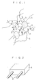
- Fig. 1 is a model diagram of a graft polymer comprising polymer molecules grafted onto graphite and carbon black in the obtained device, wherein graft polymer molecules 3 extend in a chain-like form from graphite particles 1 and carbon black particles 2 and are connected to each other at crosslinkage sites 4 to form a network structure.
- a grafting product If isolation of a grafting product is possible, it can be confirmed by examining the thermally decomposed matter of polymer combined with the surfaces of particles thereof according to gas chromatography that a crystalline polymer substance such as polyethylene or polypropylene is grafted onto the surfaces of graphite particles by using an organic peroxide such as Di-Cup during the course of milling with a heated roll mill.
- a crystalline polymer substance such as polyethylene or polypropylene
- P-OMA 2-ethylhexyl methacrylate
- P-OMA synthesized by another method was milled together with graphite with a heated roll mill at a blending ratio as shown in Table 1.
- MIBK methyl isobutyl ketone
- a radical (RO ⁇ ) formed by thermal decomposition of Di-Cup abstracts a hydrogen atom bonded to a tertiary carbon atom of P-OMA to form a polymer radical (P ⁇ ), which then reacts with a phenoxy radical present on the surface of a graphite particle to graft thereonto.
- Graphite particles onto which P-OMA is grafted in the above-mentioned way are improved in dispersibility in MIBK so that they are less liable to precipitate by centrifugal separation. This substantiates that, when graphite and P-OMA are milled together with Di-Cup with a heated roll mill, P-OMA is grafted onto the surfaces of graphite particles.
- the organic peroxide has the roles of a grafting agent and a crosslinking agent for a crystalline polymer substance.
- the organic peroxide is consumed as the grafting agent in the presence of graphite and carbon black particles because of a preferential reaction of grafting of polymer radicals onto the surfaces of the above-mentioned particles, while the polymer is crosslinked with any surplus of the organic peroxide.
- the suitable amount of an organic peroxide as the grafting agent can be found by examining the extents of gelation, due to network formation, of milled masses respectively containing appropriately varied amounts of the organic peroxide during the course of milling. Further, whether or not any amount of the organic peroxide remains in a milled mass can be confirmed by the state of molding of the milled mass.
- a test mixing roll mill was used as a milling apparatus.
- Sample No. II (Di-Cup: 2 g): about 5 minutes after incorporation of the predetermined amount of Di-Cup, a milled mass began to become slightly hard so that the turnover operation became easy. Thereafter, no change in the state of the milled mass was recognized.
- Sample No. III (Di-Cup: 4 g): about 5 minutes after incorporation of the predetermined amount of Di-Cup, a milled mass began to become slightly hard so that the turnover operation became easy. 9 minutes thereafter, the milled mass began to become leather-like. Milling was continued.
- Sample No. IV (Di-Cup: 6 g): about 4 minutes after incorporation of the predetermined amount of Di-Cup, a milled mass began to become slightly hard so that the turnover operation became easy. 8 minutes thereafter, the milled mass began to become leather-like. Milling was continued. The milled mass was more leather-like than that of Sample No. III.
- Sample No. V (Di-Cup: 8 g): about 4 minutes after incorporation of the predetermined amount of Di-Cup, a milled mass began to become leather-like. 6 minutes thereafter, the milled mass was hardened to become completely leather-like so that milling was terminated.
- the necessary amount of Di-Cup as the grafting agent is about 4 g per 100 g of electrically conductive particles. This value is close to the theoretically calculated value mentioned hereinbefore.
- First and second organic peroxides were separately added as a grafting agent and a crosslinking agent, respectively, during the course of milling with a heated roll mill to graft polyethylene onto the surfaces of carbon black and graphite particles and further crosslink the grafted polyethylene and the ungrafted polyethylene between molecules thereof to thereby form a network.
- a suitable amount of a first organic peroxide such as Di-Cup (Percumyl D)
- a suitable amount of a second organic peroxide such as TBPH-3 (Perhexyne 25B-40) simultaneously.
- the initial volume resistivity of the device 5 obtained in Example 1 which was provided with terminals 6 as shown in Fig. 2 was measured and found to be 2.84 ⁇ cm.
- a temperature cycle test one cycle: at 150°C for 15 minutes and a 25°C for 15 minutes was conducted.
- the rate of change in the electric resistance value relative to the initial value was -4.6 % after the 5th cycle and -3.6 % after the 10th cycle, thus proving that the device had a stable electric resistance.
- a device was produced in substantially the same manner as that of Example 1 except that 3 g of Di-Cup alone was added as a grafting agent without addition of any crosslinking agent.
- the initial volume resistivity of the obtained device was 1.93 ⁇ cm.
- the rate of change in the electric resistance value as measured according to the same temperature cycle test as that of Example 1 was 7.6 % after the 5th cycle and 12.9 % after the 10th cycle.
- a device was produced in substantially the same manner as that of Example 1 except that neither grafting agent nor crosslinking agent was added and that the heat treatment at 200° for 15 minutes was dispensed with to avoid deformation of the device.
- the initial volume resistivity of the obtained device was 0.30 ⁇ cm.
- the rate of change in the electric resistance value as measured according to the same temperature cycle test as that of Example 1 was 43.2 % after the 5th cycle and 61.2 % after the 10th cycle.
- a device was produced in substantially the same manner as that of Example 1 except that graphite alone was used without use of carbon black and that 4 g of Di-Cup (Percumyl D) alone was added as the organic peroxide in the step of initial milling.
- the initial volume resistivity of the obtained device was 3.10 X 10³ ⁇ cm.
- the rate of change in the electric resistance value as measured according to the same temperature cycle test as that of Example 1 was -67.3 % after the 5th cycle and -84.8 % after the 10th cycle.
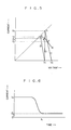
- Fig. 3 shows characteristic curves the temperature versus the rate of change in resistance value of the devices obtained in Example 1 and Comparative Examples 1 and 2. It can be understood from these characteristic curves that, after the manifestation of PTC characteristics, the device of Comparative Example 2 showed notable NTC characteristics and that of Comparative Example 1 showed slightly suppressed NTC characteristics while that of Example 1 showed largely suppressed NTC characteristics.
- Fig. 5 shows the static voltage versus current characteristic curve of the device of Example 1 as measured by connecting the device 5 in series to a load 7 and applying a voltage V from a power source 8 to the device 5 as shown in Fig. 4.
- V a voltage
- V a voltage
- the operating point settles at a point a where a steady state is attained without current limitation. This state corresponds to that attained when a rated current flows through a metallic fuse.
- a load line B is replaced by a load line C, whereupon the operating point shifts from the point a to a point b .
- the load line B is replaced by a load line D and the operating point shifts from the point a to a point b .
- the operating point shifts from the point b to a point e with some time lag and the current is limited to I ⁇ 2.
- the current value can be limited to a rated current or below though the limited current value varies depending on conditions.
- the current returns to the rated state, the operating point returns to the point a again.
- the device can be repeatedly used as an overcurrent protective device. Accordingly, utilization of these characteristics enables the use of the device as a self-restoring overcurrent protective device.
- Fig. 6 shows the dynamic time versus current characteristic curve of the device 5, which shows a variation of current with time during the course of limitation of the current from I2 to I ⁇ 2 with shift of the operating point from the point b to the point e in Fig. 5.
- the time t L spent during limitation of the current from I2 to I ⁇ 2 is a current-limiting time.
- Example 1 20 g of furnace black (Vulcan XC 72), 20 g of acetylene black (Denka Black); and 60 g of graphite (ACP-1000) were added to 100 g of polyethylene (1300J), to which 3 g of Di-Cup (Percumyl D) and 5 g of TBPH-3 (Perhexyne 25B-40) were then further added as a grafting agent for effecting grafting onto the surfaces of the above-mentioned particles and a crosslinking agent, respectively.
- a device was produced in substantially the same manner as that of Example 1 except for the above-mentioned materials.
- the initial volume resistivity of the obtained device was 1.68 ⁇ cm.
- the rate of change in the electric resistance value as measured according to the same temperature cycle test as that of Example 1 was 4.5 % after the 5th cycle and 5.0 % after the 10th cycle.
- Example 1 60 g of furnace black (Vulcan XC 72) and 40 g of graphite (artificial graphite GA-5) were added to 150 g of polyethylene (1300J), to which 3 g of Di-Cup (Percumyl D) and 5 g of TBPH-3 (Perhexyne 25B-40) were then further added as a grafting agent for effecting grafting onto the surfaces of the above-mentioned particles and a crosslinking agent, respectively.
- a device was produced in substantially the same manner as that of Example 1 except for the above-mentioned materials.
- the initial volume resistivity of the obtained device was 3.78 ⁇ cm.
- the rate of change in the electric resistance value as measured according to the same temperature cycle test as that of Example 1 was 8.9 % after the 5th cycle and 14.2 % after the 10th cycle.
- Example 1 50 g of furnace black (Vulcan XC 72) and 50 g of graphite (ACP-1000) were added to 80 g of polyethylene (1300J) and 40 g of polypropylene (J900P, melting point: about 160°C), to which 3 g of Di-Cup (Percumyl D) and 5 g of TBPH-3 (Perhexyne 25B-40) were then further added as a grafting agent for effecting grafting onto the surfaces of the above-mentioned particles and a crosslinking agent, respectively.
- a device was produced in substantially the same manner as that of Example 1 except for the above-mentioned materials.
- the initial volume resistivity of the obtained device was 4.06 ⁇ cm.
- the rate of change in the electric resistance value as measured according to the same temperature cycle test as that of Example 1 was -13.4 % after the 5th cycle and -18.7 % after the 10th cycle.
- Ketjen black was used as carbon black.
- Ketjen black (EC) and 80 g of graphite (ACP-1000) were added to 100 g of polyethylene (1300J), to which 3 g of Di-Cup (Percumyl D) and 5 g of TBPH-3 (Perhexyne 25B-40) were then further added as a grafting agent for effecting grafting onto the surfaces of the above-mentioned particles and a crosslinking agent, respectively.
- a device was produced in substantially the same manner as that of Example 1 except for the above-mentioned materials.
- the initial volume resistivity of the obtained device was 1.60 ⁇ cm.
- the rate of change in the electric resistance value as measured according to the same temperature cycle test as that of Example 1 was 14.2 % after the 5th cycle and 18.6 % after the 10th cycle.
- a device was produced in substantially the same manner as that of Example 1 except for the above-mentioned materials.
- the initial volume resistivity of the obtained device was 2.44 ⁇ cm.
- the rate of change in the electric resistance value as measured according to the same temperature cycle test as that of Example 1 was 9.1 % after the 5th cycle and 5.4 % after the 10th cycle.
- a device was produced in substantially the same manner as that of Example 1 except for the above-mentioned materials.
- the initial volume resistivity of the obtained device was 5.78 ⁇ cm.
- the rate of change in the electric resistance value as measured according to the same temperature cycle test as that in Example 1 was 7.4 % after the 5th cycle and 8.3 % after the 10th cycle.
- the rate of change in the resistance value of the device of Comparative Example 1 is better than those of the devices of some Examples.
- the device of Comparative Example 1 shows the NTC phenomenon when the temperature thereof is further raised after the manifestation of the PTC phenomenon. This results in a drastic reduction in the current-limiting characteristics of the device as an overcurrent protective device.
- the device of Comparative Example 2 also shows the same phenomenon.
- the low initial volume resistivity of the device of Comparative Example 2 as shown in Table 5 is due to the presence of aggregates of particles in the crystalline polymer substance which resulted from the poor dispersibility of the graphite and the carbon black attributed to the fact that no organic peroxide was used so that the polymer substance was not grafted onto the graphite and the carbon black. This is substantiated by the rate of change in the initial resistance value as measured according to the temperature cycle test.
- the device of Comparative Example 3 has a very high initial volume resistivity, which is attributed to the fact that no carbon black was blended. Further, the device of Comparative Example 3 shows a very high rate of change in the resistance value.
- the milling time is shortened to suppress the thermal decomposition of the organic peroxide for preventing the crosslinking of the polymer substance due to the decomposition of the organic peroxide according to the conventional process, whereas, according to the process of the present invention, a suitable amount of the organic peroxide is determined and heated together with the other materials at or above the thermal decomposition temperature thereof while sufficiently milling them to graft part of the polymer substance onto the surfaces of the particles, whereby the compatibility of the particles with the polymer substance can be improved.
- the carbon black is broken into primary particles and homogeneously dispersed in the polymer substance. Accordingly, a device having a significantly reduced scattering of resistance value can be obtained as an overcurrent protective device.
- the polymer substance is crosslinked between the molecules thereof after the completion of milling to form a three-dimensional network structure involving the graphite and carbon black particles therein, which enables the order of the electrically conductive particles, even after repeated manifestation of the PTC phenomenon (current-limiting actions), to return to the original state to provide an effect of restoring the resistance value stably to the original value.
- the network structure serves to retain the shape of the device even in a temperature range where the crystalline polymer is molten, and to provide an effect of suppressing the NTC phenomenon after the manifestation of the PTC phenomenon.
Landscapes
- Chemical & Material Sciences (AREA)
- Engineering & Computer Science (AREA)
- Microelectronics & Electronic Packaging (AREA)
- Materials Engineering (AREA)
- Physics & Mathematics (AREA)
- Electromagnetism (AREA)
- Ceramic Engineering (AREA)
- Inorganic Chemistry (AREA)
- Dispersion Chemistry (AREA)
- Health & Medical Sciences (AREA)
- Chemical Kinetics & Catalysis (AREA)
- Medicinal Chemistry (AREA)
- Polymers & Plastics (AREA)
- Organic Chemistry (AREA)
- Compositions Of Macromolecular Compounds (AREA)
- Graft Or Block Polymers (AREA)
Claims (5)
- Verfahren zur Herstellung eines selbstheilenden Schutzgegenstandes gegen Überstrom mit einer Propfmethode, mit folgenden Schritten: Hinzufügen einer geigneten Menge von organischem Peroxid als Reaktionskatalyzator zu einer Mischung, die aus kolloidalem Grafit, mindestens einer Sorte Ruß, ausgewählt aus Acetylenruß, Ketjenblack (R) und hochstrukturiertem Ofenruß und einer oder mehreren Sorten von kristallinen Polymersubstanzen besteht, Aufheizen der Mischung auf eine Temperatur, die höher als die thermische Zersetzungstemperatur des organischen Peroxids ist, un eine hohe Viskosität zu erhalten, kräftiges Mahlen der Mischung, wobei das organische Peroxid mit der Polymersubstanz reagiert, um unpaarige Elektronen der Polymersubstanz hinzuzufügen und damit Polymerradikale zu bilden, Propfen der gebildeten Polymerradikale auf den Grafit und den Ruß, um eine gemahlene Masse zu bilden, deren Propfprodukte eine solche Struktur haben, daß die Polymersubstanz mit dem Grafit verbunden wird und der Ruß homogen in Form von Primärpartikeln in der Polymersubstanz dispergiert ist, Formen der gemahlenen und thermoplastischen Masse in eine vorbestimmte Form und thermisches Zersetzen des organischen Peroxids, das nicht bei der Bildung der Polymerradikale beteiligt war, um eine vernetzende Struktur zwischen den Pfropfptodukten und der Polymersubstanz einzufügen.
- Verfahren zur Herstellung eines selbstheilenden Schutzgegenstandes gegen Überstrom mit einer Propfmethode, mit folgenden Schritten: Hinzufügen einer geigneten Menge eines ersten organischen Peroxids als Reaktionskatalysator zu einer Mischung, die aus kolloidalem Grafit, mindestens einer Sorte Ruß, ausgewählt aus Acetylenruß, Ketjenblack (R) und hochstrukturiertem Ofenruß und einer oder mehreren Sorten von kristallinen Polymersubstanzen besteht, Aufheizen der Mischung auf eine Temperatur, die höher als die thermische Zersetzungstemperatur des organischen Peroxids ist, um eine hohe Viskosität zu erhalten, kräftiges Mahlen der Mischung, wobei das organische Peroxid mit der Polymersubstanz reagiert, um unpaarige Elektronen der Polymersubstanz hinzuzufügen und damit Polymerradikale zu bilden, Propfen der gebildeten Polymerradikale auf den Grafit und den Ruß, um eine gemahlene Masse zu bilden, deren Propfprodukte eine solche Struktur haben, daß die Polymersubstanz mit dem Grafit verbunden wird und der Ruß homogen in Form von Primärpartikeln in der Polymersubstanz dispergiert ist, Hinzufügen eines zweiten organischen Peroxids zu der gemahlenen Masse, Formen der gemahlenen und thermoplastischen Masse in eine vorbestimmte Form und thermisches Zersetzen des zweiten organischen Peroxids, um eine vernetzende Struktur zwischen den Pfropfprodukten und der Polymersubstanz einzufügen.
- Verfahren zur Herstellung eines selbstheilenden Schutzgegenstandes gegen Überstrom mit der Pfropfmethode nach Anspruch 2, wobei das zweite organische Peroxid der gleiche Stoff wie das erste organische Peroxid ist.
- Verfahren zur Herstellung eines selbstheilenden Schutzgegenstandes gegen Überstrom mit der Pfropfmethode nach Anspruch 2, wobei das zweite organische Peroxid ein bei hoher Temperatur stabilerer Stoff als das erste organische Peroxid ist.
- Verfahren zur Herstellung eines selbstheilenden Schutzgegenstandes gegen Überstrom mit einer Propfmethode, mit folgenden Schritten: Hinzufügen einer geigneten Menge eines organischen Peroxids als Reaktionskatalysator zu einer Mischung, die aus kolloidalem Grafit, mindestens einer Sorte Ruß, ausgewählt aus Acetylenruß, Ketjenblack (R) und hochstrukturiertem Ofenruß und einer oder mehreren Sorten von kristallinen Polymersubstanzen besteht, Aufheizen der Mischung auf eine Temperatur, die höher als die thermische Zersetzungstemperatur des ersten organischen Peroxids ist, um eine hohe Viskosität zu erhalten, kräftiges kahlen der Mischung, wobei das organische Peroxid mit der Polymersubstanz reagiert, um unpaarige Elektronen der Polymersubstanz hinzuzufügen und damit Polymerradikale zu bilden, Propfen der gebildeten Polymerradikale auf den Grafit und den Ruß, um eine gemahlene Masse zu bilden, deren Propfprodukte eine solche Struktur haben, daß die Polymersubstanz mit dem Grafit verbunden wird und der Ruß homogen in Form von Primärpartikeln in der Polymersubstanz dispergiert ist, Formen der gemahlenen und thermoplastischen Masse in eine vorbestimmte Form und Bestrahlen der geformten Masse, um eine vernetzende Struktur zwischen den Pfropfprodukten und der Polymersubstanz einzufügen.
Applications Claiming Priority (2)
| Application Number | Priority Date | Filing Date | Title |
|---|---|---|---|
| JP184997/87 | 1987-07-24 | ||
| JP18499787 | 1987-07-24 |
Publications (3)
| Publication Number | Publication Date |
|---|---|
| EP0300810A2 EP0300810A2 (de) | 1989-01-25 |
| EP0300810A3 EP0300810A3 (en) | 1990-03-07 |
| EP0300810B1 true EP0300810B1 (de) | 1992-12-16 |
Family
ID=16162976
Family Applications (1)
| Application Number | Title | Priority Date | Filing Date |
|---|---|---|---|
| EP88306755A Expired EP0300810B1 (de) | 1987-07-24 | 1988-07-22 | Verfahren zur Herstellung eines selbstheilenden Schutzgegenstandes gegen Überstrom durch Ent-Methode |
Country Status (4)
| Country | Link |
|---|---|
| US (1) | US4880577A (de) |
| EP (1) | EP0300810B1 (de) |
| CA (1) | CA1294398C (de) |
| DE (1) | DE3876709T2 (de) |
Families Citing this family (18)
| Publication number | Priority date | Publication date | Assignee | Title |
|---|---|---|---|---|
| US5143649A (en) * | 1985-12-06 | 1992-09-01 | Sunbeam Corporation | PTC compositions containing low molecular weight polymer molecules for reduced annealing |
| JPH02140902A (ja) * | 1988-11-22 | 1990-05-30 | Tdk Corp | 有機正特性抵抗体 |
| JP2810740B2 (ja) * | 1989-12-27 | 1998-10-15 | 大東通信機株式会社 | グラフト化法によるptc組成物 |
| JPH0688350B2 (ja) * | 1990-01-12 | 1994-11-09 | 出光興産株式会社 | 正温度係数特性成形体の製造方法 |
| JPH0448701A (ja) * | 1990-06-15 | 1992-02-18 | Daito Tsushinki Kk | 自己復帰形過電流保護素子 |
| JPH0590009A (ja) * | 1991-09-26 | 1993-04-09 | Daito Tsushinki Kk | Ptc組成物 |
| US5691689A (en) * | 1995-08-11 | 1997-11-25 | Eaton Corporation | Electrical circuit protection devices comprising PTC conductive liquid crystal polymer compositions |
| US6059997A (en) * | 1995-09-29 | 2000-05-09 | Littlelfuse, Inc. | Polymeric PTC compositions |
| US5814264A (en) * | 1996-04-12 | 1998-09-29 | Littelfuse, Inc. | Continuous manufacturing methods for positive temperature coefficient materials |
| US6023403A (en) * | 1996-05-03 | 2000-02-08 | Littlefuse, Inc. | Surface mountable electrical device comprising a PTC and fusible element |
| US6282072B1 (en) | 1998-02-24 | 2001-08-28 | Littelfuse, Inc. | Electrical devices having a polymer PTC array |
| US6582647B1 (en) | 1998-10-01 | 2003-06-24 | Littelfuse, Inc. | Method for heat treating PTC devices |
| US6628498B2 (en) | 2000-08-28 | 2003-09-30 | Steven J. Whitney | Integrated electrostatic discharge and overcurrent device |
| JP2006008454A (ja) * | 2004-06-25 | 2006-01-12 | Fuji Xerox Co Ltd | 炭素微粒子構造体とその製造方法、およびこれを製造するための炭素微粒子転写体と炭素微粒子構造体製造用溶液、並びに炭素微粒子構造体を用いた炭素微粒子構造体電子素子とその製造方法、そして集積回路 |
| US8562871B2 (en) * | 2006-07-10 | 2013-10-22 | Sabic Innovative Plastics Ip B.V. | Composition and associated method |
| US20080027164A1 (en) * | 2006-07-31 | 2008-01-31 | Illinois Tool Works, Inc. | Reduced Odor RTV Silicone |
| JP5305503B2 (ja) * | 2008-05-22 | 2013-10-02 | 株式会社ピーアイ技術研究所 | 電池の電極の導電剤、それを含む電極及び電池 |
| JP5082020B2 (ja) * | 2011-02-04 | 2012-11-28 | 積水化学工業株式会社 | 薄片化黒鉛−ポリマー複合材料の製造方法 |
Family Cites Families (10)
| Publication number | Priority date | Publication date | Assignee | Title |
|---|---|---|---|---|
| US3914363A (en) * | 1972-09-08 | 1975-10-21 | Raychem Corp | Method of forming self-limiting conductive extrudates |
| US4237441A (en) * | 1978-12-01 | 1980-12-02 | Raychem Corporation | Low resistivity PTC compositions |
| DE2901758A1 (de) * | 1979-01-18 | 1980-07-31 | Basf Ag | Verfahren zur herstellung elektrisch leitender polyolefinformkoerper und deren verwendung |
| JPS592693B2 (ja) * | 1979-07-03 | 1984-01-20 | 日立電線株式会社 | 正温度係数特性を有する導電性重合体組成物並びにこれを用いたヒ−タ |
| US4318881A (en) * | 1980-05-19 | 1982-03-09 | Raychem Corporation | Method for annealing PTC compositions |
| US4511445A (en) * | 1982-06-18 | 1985-04-16 | At&T Bell Laboratories | Process of enhancing conductivity of material |
| US4514620A (en) * | 1983-09-22 | 1985-04-30 | Raychem Corporation | Conductive polymers exhibiting PTC characteristics |
| JPS61123665A (ja) * | 1984-11-19 | 1986-06-11 | Matsushita Electric Ind Co Ltd | 導電性樹脂組成物の製造方法 |
| JPS62131065A (ja) * | 1985-12-03 | 1987-06-13 | Idemitsu Kosan Co Ltd | 高分子正温度特性組成物 |
| JPH0716221B2 (ja) * | 1991-02-01 | 1995-02-22 | 株式会社日興電機製作所 | 加入者回線の遠隔測定方法および加入者回線の遠隔切り分け回路 |
-
1988
- 1988-07-19 US US07/221,333 patent/US4880577A/en not_active Expired - Lifetime
- 1988-07-22 CA CA000572890A patent/CA1294398C/en not_active Expired - Lifetime
- 1988-07-22 EP EP88306755A patent/EP0300810B1/de not_active Expired
- 1988-07-22 DE DE8888306755T patent/DE3876709T2/de not_active Expired - Fee Related
Also Published As
| Publication number | Publication date |
|---|---|
| US4880577A (en) | 1989-11-14 |
| EP0300810A3 (en) | 1990-03-07 |
| DE3876709T2 (de) | 1993-07-08 |
| DE3876709D1 (de) | 1993-01-28 |
| CA1294398C (en) | 1992-01-21 |
| EP0300810A2 (de) | 1989-01-25 |
Similar Documents
| Publication | Publication Date | Title |
|---|---|---|
| EP0300810B1 (de) | Verfahren zur Herstellung eines selbstheilenden Schutzgegenstandes gegen Überstrom durch Ent-Methode | |
| US4545926A (en) | Conductive polymer compositions and devices | |
| JP2810740B2 (ja) | グラフト化法によるptc組成物 | |
| EP0167905B1 (de) | Leitfähige wärmehärtbare Zusammensetzungen und Verfahren zu ihrer Verwendung | |
| US3056750A (en) | Resin bonded electrical resistors and methods of producing the same | |
| GB1561355A (en) | Voltage stable positive temperature coefficient of resistance compositions | |
| EP0437239A2 (de) | Verfahren zur Herstellung von einem gegossenen Gegenstand mit positivem Temperaturkoeffizient | |
| KR20070082522A (ko) | 과전류 보호 장치 | |
| GB1571014A (en) | Graft copolymer and process for producing the same | |
| US5545679A (en) | Positive temperature coefficient conductive polymer made from thermosetting polyester resin and conductive fillers | |
| CN101935418A (zh) | 正温度系数材料及其制备方法及含该材料的热敏电阻及其制备方法 | |
| US3689618A (en) | Use of an unadvanced silicone resin binder in resistor manufacture | |
| JP2592105B2 (ja) | グラフト化法による自己復帰形過電流保護素子の製造方法 | |
| WO1999030329A1 (en) | Conductive polymer compositions, electrical devices and methods of making | |
| US3742423A (en) | Electrical resistor | |
| JP2002270403A (ja) | 正抵抗温度特性抵抗体 | |
| Miyauchi et al. | Electrical properties of carbon‐black grafted with polymers using an anionic catalyst | |
| JPS6143633A (ja) | 感熱抵抗性導電性組成物の製造方法 | |
| JPS6165402A (ja) | 感熱抵抗性導電性材料およびその製法 | |
| EP0235439A1 (de) | Elektrisch leitfähige Polymere und deren Herstellung | |
| JPS63184303A (ja) | Ptc組成物の製造法 | |
| JPH09310029A (ja) | 導電性粉体カプセル化物およびその製造方法並びに導電性樹脂組成物 | |
| JPS58117239A (ja) | 高導電率の難燃性熱可塑性成形用組成物 | |
| JPS63133501A (ja) | Ptc組成物の製造法 | |
| JPH01186783A (ja) | 正温度特性発熱素子の製造方法 |
Legal Events
| Date | Code | Title | Description |
|---|---|---|---|
| PUAI | Public reference made under article 153(3) epc to a published international application that has entered the european phase |
Free format text: ORIGINAL CODE: 0009012 |
|
| AK | Designated contracting states |
Kind code of ref document: A2 Designated state(s): DE FR GB NL |
|
| PUAL | Search report despatched |
Free format text: ORIGINAL CODE: 0009013 |
|
| AK | Designated contracting states |
Kind code of ref document: A3 Designated state(s): DE FR GB NL |
|
| 17P | Request for examination filed |
Effective date: 19900824 |
|
| 17Q | First examination report despatched |
Effective date: 19920303 |
|
| GRAA | (expected) grant |
Free format text: ORIGINAL CODE: 0009210 |
|
| AK | Designated contracting states |
Kind code of ref document: B1 Designated state(s): DE FR GB NL |
|
| REF | Corresponds to: |
Ref document number: 3876709 Country of ref document: DE Date of ref document: 19930128 |
|
| ET | Fr: translation filed | ||
| PLBE | No opposition filed within time limit |
Free format text: ORIGINAL CODE: 0009261 |
|
| STAA | Information on the status of an ep patent application or granted ep patent |
Free format text: STATUS: NO OPPOSITION FILED WITHIN TIME LIMIT |
|
| 26N | No opposition filed | ||
| PGFP | Annual fee paid to national office [announced via postgrant information from national office to epo] |
Ref country code: FR Payment date: 19970709 Year of fee payment: 10 |
|
| PGFP | Annual fee paid to national office [announced via postgrant information from national office to epo] |
Ref country code: NL Payment date: 19970731 Year of fee payment: 10 |
|
| PGFP | Annual fee paid to national office [announced via postgrant information from national office to epo] |
Ref country code: GB Payment date: 19980713 Year of fee payment: 11 |
|
| PGFP | Annual fee paid to national office [announced via postgrant information from national office to epo] |
Ref country code: DE Payment date: 19980803 Year of fee payment: 11 |
|
| PG25 | Lapsed in a contracting state [announced via postgrant information from national office to epo] |
Ref country code: NL Free format text: LAPSE BECAUSE OF NON-PAYMENT OF DUE FEES Effective date: 19990201 |
|
| PG25 | Lapsed in a contracting state [announced via postgrant information from national office to epo] |
Ref country code: FR Free format text: LAPSE BECAUSE OF NON-PAYMENT OF DUE FEES Effective date: 19990331 |
|
| NLV4 | Nl: lapsed or anulled due to non-payment of the annual fee |
Effective date: 19990201 |
|
| REG | Reference to a national code |
Ref country code: FR Ref legal event code: ST |
|
| PG25 | Lapsed in a contracting state [announced via postgrant information from national office to epo] |
Ref country code: GB Free format text: LAPSE BECAUSE OF NON-PAYMENT OF DUE FEES Effective date: 19990722 |
|
| GBPC | Gb: european patent ceased through non-payment of renewal fee |
Effective date: 19990722 |
|
| PG25 | Lapsed in a contracting state [announced via postgrant information from national office to epo] |
Ref country code: DE Free format text: LAPSE BECAUSE OF NON-PAYMENT OF DUE FEES Effective date: 20000503 |