EP0298397B1 - Disposition de commande pour un véhicule - Google Patents
Disposition de commande pour un véhicule Download PDFInfo
- Publication number
- EP0298397B1 EP0298397B1 EP88110574A EP88110574A EP0298397B1 EP 0298397 B1 EP0298397 B1 EP 0298397B1 EP 88110574 A EP88110574 A EP 88110574A EP 88110574 A EP88110574 A EP 88110574A EP 0298397 B1 EP0298397 B1 EP 0298397B1
- Authority
- EP
- European Patent Office
- Prior art keywords
- motor vehicle
- drive
- axle gear
- differential axle
- intermediate differential
- Prior art date
- Legal status (The legal status is an assumption and is not a legal conclusion. Google has not performed a legal analysis and makes no representation as to the accuracy of the status listed.)
- Expired - Lifetime
Links
- 238000002485 combustion reaction Methods 0.000 claims description 20
- 230000005540 biological transmission Effects 0.000 claims description 3
- 230000000694 effects Effects 0.000 claims 3
- 230000007423 decrease Effects 0.000 description 5
- 239000012530 fluid Substances 0.000 description 4
- 230000001771 impaired effect Effects 0.000 description 2
- 238000013459 approach Methods 0.000 description 1
- 230000003247 decreasing effect Effects 0.000 description 1
- 230000001419 dependent effect Effects 0.000 description 1
- 230000002349 favourable effect Effects 0.000 description 1
- 238000000034 method Methods 0.000 description 1
- 230000007935 neutral effect Effects 0.000 description 1
- 230000002035 prolonged effect Effects 0.000 description 1
Images
Classifications
-
- B—PERFORMING OPERATIONS; TRANSPORTING
- B60—VEHICLES IN GENERAL
- B60T—VEHICLE BRAKE CONTROL SYSTEMS OR PARTS THEREOF; BRAKE CONTROL SYSTEMS OR PARTS THEREOF, IN GENERAL; ARRANGEMENT OF BRAKING ELEMENTS ON VEHICLES IN GENERAL; PORTABLE DEVICES FOR PREVENTING UNWANTED MOVEMENT OF VEHICLES; VEHICLE MODIFICATIONS TO FACILITATE COOLING OF BRAKES
- B60T8/00—Arrangements for adjusting wheel-braking force to meet varying vehicular or ground-surface conditions, e.g. limiting or varying distribution of braking force
- B60T8/32—Arrangements for adjusting wheel-braking force to meet varying vehicular or ground-surface conditions, e.g. limiting or varying distribution of braking force responsive to a speed condition, e.g. acceleration or deceleration
- B60T8/321—Arrangements for adjusting wheel-braking force to meet varying vehicular or ground-surface conditions, e.g. limiting or varying distribution of braking force responsive to a speed condition, e.g. acceleration or deceleration deceleration
- B60T8/322—Systems specially adapted for vehicles driven by more than one axle, e.g. Four Wheel-Drive vehicles
-
- B—PERFORMING OPERATIONS; TRANSPORTING
- B60—VEHICLES IN GENERAL
- B60K—ARRANGEMENT OR MOUNTING OF PROPULSION UNITS OR OF TRANSMISSIONS IN VEHICLES; ARRANGEMENT OR MOUNTING OF PLURAL DIVERSE PRIME-MOVERS IN VEHICLES; AUXILIARY DRIVES FOR VEHICLES; INSTRUMENTATION OR DASHBOARDS FOR VEHICLES; ARRANGEMENTS IN CONNECTION WITH COOLING, AIR INTAKE, GAS EXHAUST OR FUEL SUPPLY OF PROPULSION UNITS IN VEHICLES
- B60K17/00—Arrangement or mounting of transmissions in vehicles
- B60K17/34—Arrangement or mounting of transmissions in vehicles for driving both front and rear wheels, e.g. four wheel drive vehicles
- B60K17/344—Arrangement or mounting of transmissions in vehicles for driving both front and rear wheels, e.g. four wheel drive vehicles having a transfer gear
- B60K17/346—Arrangement or mounting of transmissions in vehicles for driving both front and rear wheels, e.g. four wheel drive vehicles having a transfer gear the transfer gear being a differential gear
- B60K17/3462—Arrangement or mounting of transmissions in vehicles for driving both front and rear wheels, e.g. four wheel drive vehicles having a transfer gear the transfer gear being a differential gear with means for changing distribution of torque between front and rear wheels
-
- B—PERFORMING OPERATIONS; TRANSPORTING
- B60—VEHICLES IN GENERAL
- B60K—ARRANGEMENT OR MOUNTING OF PROPULSION UNITS OR OF TRANSMISSIONS IN VEHICLES; ARRANGEMENT OR MOUNTING OF PLURAL DIVERSE PRIME-MOVERS IN VEHICLES; AUXILIARY DRIVES FOR VEHICLES; INSTRUMENTATION OR DASHBOARDS FOR VEHICLES; ARRANGEMENTS IN CONNECTION WITH COOLING, AIR INTAKE, GAS EXHAUST OR FUEL SUPPLY OF PROPULSION UNITS IN VEHICLES
- B60K23/00—Arrangement or mounting of control devices for vehicle transmissions, or parts thereof, not otherwise provided for
- B60K23/08—Arrangement or mounting of control devices for vehicle transmissions, or parts thereof, not otherwise provided for for changing number of driven wheels, for switching from driving one axle to driving two or more axles
- B60K23/0808—Arrangement or mounting of control devices for vehicle transmissions, or parts thereof, not otherwise provided for for changing number of driven wheels, for switching from driving one axle to driving two or more axles for varying torque distribution between driven axles, e.g. by transfer clutch
-
- B—PERFORMING OPERATIONS; TRANSPORTING
- B60—VEHICLES IN GENERAL
- B60W—CONJOINT CONTROL OF VEHICLE SUB-UNITS OF DIFFERENT TYPE OR DIFFERENT FUNCTION; CONTROL SYSTEMS SPECIALLY ADAPTED FOR HYBRID VEHICLES; ROAD VEHICLE DRIVE CONTROL SYSTEMS FOR PURPOSES NOT RELATED TO THE CONTROL OF A PARTICULAR SUB-UNIT
- B60W2540/00—Input parameters relating to occupants
- B60W2540/18—Steering angle
Definitions
- the invention relates to a drive arrangement for a motor vehicle with a front and a rear axle permanently driven via an axle differential and an intermediate axle differential driving the axle differential via a front and a rear output shaft, to which an intermediate axle differential lock is assigned and which in the unlocked state has a specific, structurally predetermined Distribution of drive torque between the front axle and the rear axle.
- a drive arrangement that makes this possible is already known from DE-C-35 16 982.
- the distribution of the drive torque to the front axle and to the rear axle can be changed depending on the steering angle of the front wheels in such a way that the share of drive torque on the front axle decreases to 15% when cornering in extreme cases and the share of drive torque on the Rear axle increases accordingly to a maximum of 85%.
- the variability of the drive torque distribution is achieved in the known drive arrangement in that a self-locking intermediate axle differential lock in the form of a fluid friction clutch is assigned to the intermediate axle differential and that a controllable friction clutch is provided in the drive train to the front wheels.
- this known drive arrangement has a number of disadvantages: since the degree of locking of the self-locking intermediate axle differential lock is a function of the speed difference between the front and rear output shafts of the intermediate axle differential, this self-locking intermediate axle differential lock builds due to the different wheel diameters of the individual motor vehicle wheels and due to the different slip in the case of asymmetrical ones Basic distribution always a locking torque that leads to a tension between the two drive axles. This tension leads to an unsteady drive torque distribution on the two drive axles and is thus impaired by the constant Change between understeer and oversteer tendency the driving dynamics of the motor vehicle. The bracing of the two drive axles also affects the control quality of an anti-lock braking system used in the motor vehicle.
- axle differential gear ratios and / or the intermediate axle differential gear ratio and / or the ratio of the tire sizes of the front and rear wheels of the motor vehicle are set such that when the intermediate axle differential is unlocked, its front and rear output shafts in normal, largely slip-free Driving operation of the motor vehicle sets a small, defined speed difference, and that the interaxle differential lock can be controlled by means of a control unit with regard to its degree of locking.
- the axle differential gear ratios and / or the intermediate axle differential gear ratio and / or the ratio of the tire sizes of the front and rear wheels of the motor vehicle are set such that in normal, largely slip-free driving operation of the motor vehicle, the speed of the front output shaft of the unlocked intermediate axle differential is lower than the speed of the rear one Output shaft, then by continuously increasing the degree of locking of the interaxle differential lock by the control unit, the proportion of the drive torque transmitted to the front axle can be increased and, at the same time, the proportion of the drive torque transmitted to the rear axle can be reduced. In this way, a reinforced front wheel drive can be generated, whereby the driving behavior of the motor vehicle is influenced in an understeering direction.
- axle differential gear ratios and / or the intermediate axle differential gear ratio and / or the ratio of the tire sizes of the front and rear wheels of the motor vehicle are set such that in normal, largely slip-free driving operation of the motor vehicle, the speed of the front output shaft of the unlocked intermediate axis differential gear is greater than the speed of the rear one Output shaft, so by increasing the degree of locking of the interaxle differential lock due to a corresponding control by the control unit, the drive torque distribution between the front axle and Rear axle are changed so that as the degree of locking of the interaxle differential lock increases, the proportion of drive torque transmitted to the front axle continuously decreases and the proportion of drive torque transmitted to the rear axle increases continuously accordingly.
- the drive arrangement according to the invention is distinguished from the known drive arrangement in particular by its simpler structural design, since in order to change the torque distribution, in contrast to the known drive arrangement, in which a fluid friction clutch and a controllable friction clutch are used, it requires only a single controllable clutch as an interaxle differential lock. Since this interaxle differential lock is only activated if a change in the drive torque distribution between the front axle and the rear axle is to be made by a locking torque build-up and is otherwise completely out of operation, this results in a difference from the known drive arrangement in which the self-locking fluid friction clutch due to different wheel diameters and is permanently effective due to different slip with asymmetrical basic distribution, a significantly better efficiency. Furthermore, due to the complete decoupling of the drive axles during normal driving, the control quality of an anti-lock braking system installed in the vehicle is not impaired.
- the interaxle differential (12) increases the degree of locking of the interaxle differential lock (30) when, due to slip occurring on the rear wheels of the motor vehicle, the speed of the rear output shaft (48) of the interaxle differential (12) is the speed of the front output shaft (36 ) of the intermediate axle differential (12) reached or exceeded.
- axle differential gear ratios and / or the intermediate axle differential gear ratio and / or the ratio of the tire sizes of the front and rear wheels of the motor vehicle are preferably selected such that the speed difference between the front and rear output shafts of the intermediate axle differential gear is between 1.5% and 3%, preferably 2% of the speed the front or rear output shaft.
- the speed difference should not be too small due to the tire tolerances and wear to be taken into account, but on the other hand it should not be greater than absolutely necessary.
- a controllable dry friction or wet friction multi-plate clutch is advantageously used as an interaxle differential lock and an electronic control unit, for example a microcomputer, is used as the control unit.
- the control unit controls the degree of locking of the intermediate axle differential lock depending on the steering angle of the motor vehicle.
- the degree of locking of the interaxle differential lock is continuously increased as the steering angle of the motor vehicle increases when the motor speed is higher than the speed of the rear output shaft in the normal driving operation of the front output shaft of the intermediate axle differential.
- the control unit controls the degree of locking of the intermediate axle differential lock depending on the drive power output by the internal combustion engine of the motor vehicle.
- the rotational speed of the front output shaft of the interaxle differential gear is greater than the speed of the rear output shaft, and the degree of locking of the interaxle differential gear lock with increasing number of the internal combustion engine of the motor vehicle each given drive power is reduced, whereby the proportion of drive torque supplied to the front axle of the motor vehicle increases with increasing drive power of the internal combustion engine, and the oversteering tendency thereby decreases.
- a drive torque distribution between the front axle and the rear axle of the motor vehicle is achieved which is dependent on the weight distribution of the motor vehicle and on the dynamic axle load distribution and is favorable in the sense of an optimal torque transmission to the drive wheels of the motor vehicle.
- the one from the The internal combustion engine of the motor vehicle each output power is determined in a simple manner by the control unit on the basis of the detected engine speed, the detected intake manifold vacuum and the detected throttle valve or accelerator pedal position.
- the control unit controls the degree of locking of the intermediate axle differential lock depending on the driving speed of the motor vehicle.
- the rotational speed of the front output shaft of the intermediate axle differential is higher than the speed of the rear output shaft, especially when the motor vehicle is cornering, the degree of locking of the intermediate axle differential lock is reduced with increasing driving speed of the motor vehicle. whereby the proportion of drive torque supplied to the front axle increases and the proportion of drive torque supplied to the rear axle decreases accordingly.
- the driving speed of the motor vehicle is determined by the control unit on the basis of the detected wheel speeds of the motor vehicle.
- the degree of locking of the intermediate axle differential lock is reduced to its minimum value if the driving speed of the motor vehicle falls below a predetermined limit value, for example 10 km / h.
- the control unit raises the degree of locking of the intermediate axle differential lock to the maximum value if, at the same time, the determined driving speed of the motor vehicle is zero, the motor vehicle brake is actuated, the engine speed is equal to the idling speed, the throttle valve or accelerator pedal position is equal to the idling position, none or the first gear of the speed change gear of the motor vehicle is engaged and the motor vehicle clutch is disengaged, and the control unit reduces the degree of locking of the intermediate axle differential lock to the minimum value, if at the same time the determined driving speed of the motor vehicle is greater than zero, the throttle valve or accelerator pedal position deviates from the idle position, the engine speed is greater than the idle speed and the motor vehicle clutch is engaged.
- the two drive axles are braced, which acts as a rollback brake and thus enable a rollback-free start of the motor vehicle on the mountain without the handbrake must be operated.
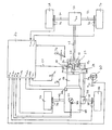
- the planet gear carrier 10 of an intermediate axle differential 12 is driven by an internal combustion engine 18 via the drive shaft 14 and a speed change gear 16.
- the central gear 22 and the outer ring gear 24 of the Interaxle differential 12 driven.
- the central gear 22 and the outer ring gear 24 of the intermediate axle differential gear 12 can be connected to one another in a rotationally fixed manner by an intermediate axle differential gear lock 30 controlled by a control unit 26 via a control line 28.
- the central gear 22 drives the front output shaft 36 of the intermediate axle differential 12 via a hollow shaft 32 and a non-rotatable connection 34.
- This front output shaft 36 drives the front wheels 44 and 46 of a motor vehicle equipped with the drive arrangement shown, via a front axle differential 38 and via front cardan shafts 40 and 42.
- the outer ring gear 24 of the intermediate axle differential 12 drives the rear wheels 56 and 58 of the motor vehicle via the rear output shaft 48, the rear axle differential 50 and the rear cardan shafts 52 and 54.
- axle differential gear ratios i VA and i HA and / or the intermediate axle differential gear ratio and / or the ratio of the tire sizes between the front wheels 44 and 46 and the rear wheels 56 and 58 of the motor vehicle are set such that a small defined speed difference occurs between the front output shaft 36 and the rear output shaft 48 in the normal, largely slip-free driving mode of the motor vehicle when the intermediate axle differential gear 12 is unlocked, and on the other hand that the intermediate axis differential gear lock 30 is established by the electronic control unit 26, which can be formed by a microcomputer, is controllable in terms of its degree of locking.
- the speed of the front output shaft 36 of the unlocked intermediate axle differential 12 may be greater than the speed of the rear output shaft 48 of the intermediate axle differential 12.
- the speed difference should preferably be 2% of the speed of the front output shaft 36 or the rear output shaft 48.
- the degree of locking of the intermediate axle differential lock 30 should be controlled as a function of the steering angle ⁇ L of the motor vehicle in such a way that the degree of lock of the intermediate axle differential 30 is continuously increased with increasing steering angle ⁇ L.
- This has the consequence that with increasing steering angle ⁇ L the proportion of the drive torque on the front wheels 44 and 46 decreases when cornering and the proportion of the drive torque on the rear wheels 56 and 58 increases. In this way, targeted oversteering of the motor vehicle in curves is possible.
- the steering angle ⁇ L again approaches zero at the exit of the curve (straight-ahead driving)
- the degree of locking of the intermediate axle differential lock 30 is continuously reduced to zero again with decreasing steering angle ⁇ L.
- the steering angle ⁇ L is detected by a steering angle sensor 60.
- This can be arranged, for example, when using a rack and pinion steering system (not shown in the figure) on the housing and can sense the position of the rack which can be displaced in the housing and deliver a steering angle signal which indicates the set steering angle ⁇ L and is supplied to the electronic control unit 26.
- the respective drive power output by the internal combustion engine 18 is a parameter for controlling the degree of locking of the intermediate axle differential lock 30.
- the degree of lock of the intermediate axle differential lock 30 is to increase with increasing engine 18, in particular when the motor vehicle is cornering of the motor vehicle output power can be reduced. It is thereby achieved that the proportion of the drive torque transmitted to the front wheels 44 and 46 increases as the drive power delivered by the internal combustion engine 18 increases when driving through curves. An amplified front-wheel drive is thereby achieved which influences the driving behavior of the motor vehicle in the "understeering" direction.
- the drive power output by the internal combustion engine 18 is calculated by the control unit 26.
- the control unit 26 receives the engine speed n Mot detected by a speed sensor 62, the throttle valve angle ⁇ D recorded by a throttle valve angle sensor 64 and the intake manifold vacuum p S detected by a pressure sensor 66 arranged in the intake manifold of the internal combustion engine 18.
- the driving speed of the motor vehicle represents a third parameter for controlling the degree of locking of the interaxle differential lock 30.
- the degree of locking of the intermediate differential lock 30 is reduced with increasing driving speed of the motor vehicle, particularly when the motor vehicle is cornering. This means that the increasing the driving torque distribution between the front wheels 44 and 46 and the rear wheels 56 and 58, which affects the driving behavior of the motor vehicle in curves with increasing driving speed in the direction of "neutral” or "understeering".
- the driving speed of the motor vehicle is calculated by the control unit 26 on the basis of the wheel speeds n VL , n VR , n HL and n HR detected by the speed sensors 68, 70, 72 and 74.
- the degree of locking of the intermediate axle differential lock 30 is reduced to its minimum value when the driving speed of the motor vehicle falls below a predetermined limit value, for example 10 km / h.
- the drive arrangement shown serves to change the drive torque distribution between the front wheels 44 and 46 and the rear wheels 56 and 58 depending on the parameters steering angle ⁇ L , drive power of the internal combustion engine 18 and driving speed of the motor vehicle.
- the drive arrangement shown also serves as a roll-back brake when starting the motor vehicle on the mountain. So that such a roll-back brake can be automatically activated or deactivated by the control unit 26, the clutch pedal travel KPW, the actuation of the brake (BS) and the position of the shift lever 76 of the speed change gearbox 16 must also be recorded in addition to the parameters already recorded.
- the roll-back brake is activated, ie the degree of locking of the intermediate axle differential lock 30 is increased to the maximum value if the driving speed of the motor vehicle determined by the wheel speeds n VL , n VR , n HL and n HR simultaneously, the motor vehicle brake actuates, the engine speed n Mot. equal to the idling speed, the throttle valve angle ⁇ D equal to the throttle valve angle when the internal combustion engine 18 is idling, no or the first gear of the speed change gear 16 of the motor vehicle is engaged and the motor vehicle clutch is disengaged.
- the roll-back brake is deactivated again, ie the degree of locking of the intermediate axle differential lock 30 is reduced to the minimum value.
Landscapes
- Engineering & Computer Science (AREA)
- Transportation (AREA)
- Mechanical Engineering (AREA)
- Chemical & Material Sciences (AREA)
- Combustion & Propulsion (AREA)
- Arrangement And Driving Of Transmission Devices (AREA)
- Hybrid Electric Vehicles (AREA)
Claims (18)
Applications Claiming Priority (2)
| Application Number | Priority Date | Filing Date | Title |
|---|---|---|---|
| DE19873722205 DE3722205A1 (de) | 1987-07-04 | 1987-07-04 | Antriebsanordnung fuer ein kraftfahrzeug |
| DE3722205 | 1987-07-04 |
Publications (3)
| Publication Number | Publication Date |
|---|---|
| EP0298397A2 EP0298397A2 (fr) | 1989-01-11 |
| EP0298397A3 EP0298397A3 (en) | 1989-04-26 |
| EP0298397B1 true EP0298397B1 (fr) | 1991-04-24 |
Family
ID=6330948
Family Applications (1)
| Application Number | Title | Priority Date | Filing Date |
|---|---|---|---|
| EP88110574A Expired - Lifetime EP0298397B1 (fr) | 1987-07-04 | 1988-07-01 | Disposition de commande pour un véhicule |
Country Status (3)
| Country | Link |
|---|---|
| EP (1) | EP0298397B1 (fr) |
| DE (2) | DE3722205A1 (fr) |
| ES (1) | ES2022538B3 (fr) |
Families Citing this family (12)
| Publication number | Priority date | Publication date | Assignee | Title |
|---|---|---|---|---|
| DE3908091A1 (de) * | 1989-03-13 | 1990-09-20 | Viscodrive Gmbh | Begrenzt sperrbares stirnraddifferential |
| WO1990011908A1 (fr) * | 1989-04-07 | 1990-10-18 | Zahnradfabrik Friedrichshafen Ag | Dispositif pour le blocage automatique d'une boite de transfert |
| JPH03217336A (ja) * | 1990-01-19 | 1991-09-25 | Mazda Motor Corp | 車両の差動制限装置 |
| DE4111615A1 (de) * | 1991-04-10 | 1992-10-15 | Daimler Benz Ag | Fahrzeug mit allradantrieb unter verwendung eines zentralen ausgleichsgetriebes mit einer regelbaren sperrkupplung |
| US5809443A (en) * | 1994-12-09 | 1998-09-15 | Ford Motor Company | Four-wheel drive transfer case controller with compensation for tires with different diameters |
| DE19706720A1 (de) * | 1996-04-06 | 1997-10-09 | Volkswagen Ag | Verfahren zum Steuern einer steuerbaren Kupplung eines Kraftfahrzeuges mit Vierradantrieb |
| US5954778A (en) * | 1996-11-26 | 1999-09-21 | Ford Global Technologies, Inc. | Four-wheel drive transfer case controller with torque decrement strategy |
| US6047231A (en) * | 1997-06-06 | 2000-04-04 | Ford Global Technologies, Inc. | Four wheel drive transfer case controller compatible with a spare tire |
| US5979584A (en) * | 1997-07-25 | 1999-11-09 | Ford Global Technologies, Inc. | Four-wheel drive transfer case controller |
| DE10248090B4 (de) * | 2002-10-15 | 2012-08-09 | Volkswagen Ag | Verfahren und Vorrichtung zur Antriebssteuerung eines Kraftfahrzeuges |
| GB0423677D0 (en) * | 2004-10-25 | 2004-11-24 | Prodrive 2000 Ltd | Improved four wheel drive system |
| DE102010009665B4 (de) * | 2010-02-27 | 2017-08-03 | Bayerische Motoren Werke Aktiengesellschaft | Verfahren zur Steuerung des Drehmoments eines Antriebsmotors in einem Kraftfahrzeug |
Family Cites Families (7)
| Publication number | Priority date | Publication date | Assignee | Title |
|---|---|---|---|---|
| US3748928A (en) * | 1971-09-20 | 1973-07-31 | Borg Warner | Control system for mutiple driving axle vehicle |
| JPS61143227A (ja) * | 1984-12-18 | 1986-06-30 | Nissan Motor Co Ltd | 車両駆動装置 |
| DE3507490C1 (de) * | 1985-03-02 | 1986-03-13 | Dr.Ing.H.C. F. Porsche Ag, 7000 Stuttgart | Sperrsystem fuer ein Kraftfahrzeug mit Allradantrieb |
| DE3516982C1 (de) * | 1985-05-10 | 1986-06-26 | Audi AG, 8070 Ingolstadt | Allradgetriebenes Kraftfahrzeug |
| JPS6231529A (ja) * | 1985-08-05 | 1987-02-10 | Nissan Motor Co Ltd | 4輪駆動車の駆動力配分制御装置 |
| DE3631180A1 (de) * | 1985-09-13 | 1987-04-02 | Nissan Motor | Steuersystem fuer die verteilung des antriebsdrehmoments bei einem 4-rad-antrieb fuer ein fahrzeug |
| US4645029A (en) * | 1985-11-05 | 1987-02-24 | Toyota Jidosha Kabushiki Kaisha | Four-wheel vehicle drive system |
-
1987
- 1987-07-04 DE DE19873722205 patent/DE3722205A1/de not_active Withdrawn
-
1988
- 1988-07-01 DE DE8888110574T patent/DE3862533D1/de not_active Expired - Lifetime
- 1988-07-01 ES ES88110574T patent/ES2022538B3/es not_active Expired - Lifetime
- 1988-07-01 EP EP88110574A patent/EP0298397B1/fr not_active Expired - Lifetime
Also Published As
| Publication number | Publication date |
|---|---|
| EP0298397A2 (fr) | 1989-01-11 |
| DE3722205A1 (de) | 1989-01-12 |
| DE3862533D1 (de) | 1991-05-29 |
| EP0298397A3 (en) | 1989-04-26 |
| ES2022538B3 (es) | 1991-12-01 |
Similar Documents
| Publication | Publication Date | Title |
|---|---|---|
| DE3437435C2 (de) | Anordnung zur Steuerung der Kraftübertragung eines vierradangetriebenen Fahrzeuges | |
| DE69935090T2 (de) | Drehmomentverteilungsregelsystem für ein allradgetriebenes Fahrzeug | |
| DE3427725C2 (fr) | ||
| DE3878642T2 (de) | Kraftuebertragung fuer ein fahrzeug mit allradantrieb. | |
| DE102006026188B4 (de) | Verfahren zum Verteilen von Antriebsmoment | |
| DE69019265T2 (de) | Steuerung der Verteilung des Drehmomentes auf das rechte und das linke Rad eines Kraftfahrzeuges. | |
| EP1203687B1 (fr) | Système de contrôle de distribution variable du couple | |
| WO2006029684A1 (fr) | Transmission et procede permettant de commander une transmission | |
| DE69003299T2 (de) | Kontrollsystem für die Drehmomentverteilung in einem Kraftfahrzeug mit Vierradantrieb. | |
| EP1732777B1 (fr) | Ensemble transmission conçu pour un vehicule automobile | |
| DE3621225C1 (de) | Steuereinrichtung fuer die zeitweise Umschaltung eines Fahrzeugantriebes von einachsigem Antrieb ueber eine permanent angetriebene Fahrzeugachse auf zweiachsigen Antrieb | |
| DE3437436C2 (de) | Anordnung zur Steuerung der Kraftübertragung eines vierradangetriebenen Fahrzeuges | |
| EP1837225A2 (fr) | Système d'entraînement pour quatre roues de véhicule | |
| EP0298397B1 (fr) | Disposition de commande pour un véhicule | |
| DE4213435A1 (de) | Steuersystem fuer ein differential | |
| DE69003159T2 (de) | Kraftübertragungssystem für ein vierradgetriebenes Kraftfahrzeug. | |
| DE102017204354B4 (de) | Verfahren zum Betreiben eines geländegängigen Fahrzeuges mit Knicklenkung | |
| DE3708193C2 (fr) | ||
| EP2353916B1 (fr) | Procédé de commande pour un agencement d'embrayage et conducteur de commande pour un véhicule automobile | |
| DE3840004A1 (de) | Kraftfahrzeug mit ueber differentialgetriebe od. dgl. angetriebenen raedern | |
| DE60205489T2 (de) | Fahrzeug mit getriebeanordnung für ein lenkbares radpaar | |
| DE10313386A1 (de) | Kraftübertragungseinheit mit einem Zentraldifferential | |
| DE3612189C2 (fr) | ||
| DE19539670B4 (de) | Drehmomentverteilungs-Steuersystem | |
| EP1648729B1 (fr) | Dispositif de commande pour vehicule automobile a quatre roues motrices au moins de façon intermittente |
Legal Events
| Date | Code | Title | Description |
|---|---|---|---|
| PUAI | Public reference made under article 153(3) epc to a published international application that has entered the european phase |
Free format text: ORIGINAL CODE: 0009012 |
|
| AK | Designated contracting states |
Kind code of ref document: A2 Designated state(s): DE ES FR GB IT SE |
|
| PUAL | Search report despatched |
Free format text: ORIGINAL CODE: 0009013 |
|
| AK | Designated contracting states |
Kind code of ref document: A3 Designated state(s): DE ES FR GB IT SE |
|
| 17P | Request for examination filed |
Effective date: 19891017 |
|
| 17Q | First examination report despatched |
Effective date: 19901004 |
|
| GRAA | (expected) grant |
Free format text: ORIGINAL CODE: 0009210 |
|
| AK | Designated contracting states |
Kind code of ref document: B1 Designated state(s): DE ES FR GB IT SE |
|
| ET | Fr: translation filed | ||
| GBT | Gb: translation of ep patent filed (gb section 77(6)(a)/1977) | ||
| REF | Corresponds to: |
Ref document number: 3862533 Country of ref document: DE Date of ref document: 19910529 |
|
| ITF | It: translation for a ep patent filed | ||
| PLBE | No opposition filed within time limit |
Free format text: ORIGINAL CODE: 0009261 |
|
| STAA | Information on the status of an ep patent application or granted ep patent |
Free format text: STATUS: NO OPPOSITION FILED WITHIN TIME LIMIT |
|
| 26N | No opposition filed | ||
| EAL | Se: european patent in force in sweden |
Ref document number: 88110574.6 |
|
| PGFP | Annual fee paid to national office [announced via postgrant information from national office to epo] |
Ref country code: ES Payment date: 19970704 Year of fee payment: 10 |
|
| PGFP | Annual fee paid to national office [announced via postgrant information from national office to epo] |
Ref country code: FR Payment date: 19970729 Year of fee payment: 10 |
|
| PG25 | Lapsed in a contracting state [announced via postgrant information from national office to epo] |
Ref country code: ES Free format text: LAPSE BECAUSE OF EXPIRATION OF PROTECTION Effective date: 19980702 |
|
| PG25 | Lapsed in a contracting state [announced via postgrant information from national office to epo] |
Ref country code: FR Free format text: LAPSE BECAUSE OF NON-PAYMENT OF DUE FEES Effective date: 19990331 |
|
| REG | Reference to a national code |
Ref country code: FR Ref legal event code: ST |
|
| PGFP | Annual fee paid to national office [announced via postgrant information from national office to epo] |
Ref country code: SE Payment date: 19990705 Year of fee payment: 12 |
|
| PG25 | Lapsed in a contracting state [announced via postgrant information from national office to epo] |
Ref country code: SE Free format text: LAPSE BECAUSE OF NON-PAYMENT OF DUE FEES Effective date: 20000702 |
|
| REG | Reference to a national code |
Ref country code: ES Ref legal event code: FD2A Effective date: 20010201 |
|
| EUG | Se: european patent has lapsed |
Ref document number: 88110574.6 |
|
| REG | Reference to a national code |
Ref country code: GB Ref legal event code: IF02 |
|
| PG25 | Lapsed in a contracting state [announced via postgrant information from national office to epo] |
Ref country code: IT Free format text: LAPSE BECAUSE OF NON-PAYMENT OF DUE FEES;WARNING: LAPSES OF ITALIAN PATENTS WITH EFFECTIVE DATE BEFORE 2007 MAY HAVE OCCURRED AT ANY TIME BEFORE 2007. THE CORRECT EFFECTIVE DATE MAY BE DIFFERENT FROM THE ONE RECORDED. Effective date: 20050701 |
|
| PGFP | Annual fee paid to national office [announced via postgrant information from national office to epo] |
Ref country code: DE Payment date: 20070822 Year of fee payment: 20 |
|
| PGFP | Annual fee paid to national office [announced via postgrant information from national office to epo] |
Ref country code: GB Payment date: 20070726 Year of fee payment: 20 |
|
| REG | Reference to a national code |
Ref country code: GB Ref legal event code: PE20 Expiry date: 20080630 |
|
| PG25 | Lapsed in a contracting state [announced via postgrant information from national office to epo] |
Ref country code: GB Free format text: LAPSE BECAUSE OF EXPIRATION OF PROTECTION Effective date: 20080630 |