EP0298397B1 - Motor vehicle drive arrangement - Google Patents
Motor vehicle drive arrangement Download PDFInfo
- Publication number
- EP0298397B1 EP0298397B1 EP88110574A EP88110574A EP0298397B1 EP 0298397 B1 EP0298397 B1 EP 0298397B1 EP 88110574 A EP88110574 A EP 88110574A EP 88110574 A EP88110574 A EP 88110574A EP 0298397 B1 EP0298397 B1 EP 0298397B1
- Authority
- EP
- European Patent Office
- Prior art keywords
- motor vehicle
- drive
- axle gear
- differential axle
- intermediate differential
- Prior art date
- Legal status (The legal status is an assumption and is not a legal conclusion. Google has not performed a legal analysis and makes no representation as to the accuracy of the status listed.)
- Expired - Lifetime
Links
Images
Classifications
-
- B—PERFORMING OPERATIONS; TRANSPORTING
- B60—VEHICLES IN GENERAL
- B60T—VEHICLE BRAKE CONTROL SYSTEMS OR PARTS THEREOF; BRAKE CONTROL SYSTEMS OR PARTS THEREOF, IN GENERAL; ARRANGEMENT OF BRAKING ELEMENTS ON VEHICLES IN GENERAL; PORTABLE DEVICES FOR PREVENTING UNWANTED MOVEMENT OF VEHICLES; VEHICLE MODIFICATIONS TO FACILITATE COOLING OF BRAKES
- B60T8/00—Arrangements for adjusting wheel-braking force to meet varying vehicular or ground-surface conditions, e.g. limiting or varying distribution of braking force
- B60T8/32—Arrangements for adjusting wheel-braking force to meet varying vehicular or ground-surface conditions, e.g. limiting or varying distribution of braking force responsive to a speed condition, e.g. acceleration or deceleration
- B60T8/321—Arrangements for adjusting wheel-braking force to meet varying vehicular or ground-surface conditions, e.g. limiting or varying distribution of braking force responsive to a speed condition, e.g. acceleration or deceleration deceleration
- B60T8/322—Systems specially adapted for vehicles driven by more than one axle, e.g. Four Wheel-Drive vehicles
-
- B—PERFORMING OPERATIONS; TRANSPORTING
- B60—VEHICLES IN GENERAL
- B60K—ARRANGEMENT OR MOUNTING OF PROPULSION UNITS OR OF TRANSMISSIONS IN VEHICLES; ARRANGEMENT OR MOUNTING OF PLURAL DIVERSE PRIME-MOVERS IN VEHICLES; AUXILIARY DRIVES FOR VEHICLES; INSTRUMENTATION OR DASHBOARDS FOR VEHICLES; ARRANGEMENTS IN CONNECTION WITH COOLING, AIR INTAKE, GAS EXHAUST OR FUEL SUPPLY OF PROPULSION UNITS IN VEHICLES
- B60K17/00—Arrangement or mounting of transmissions in vehicles
- B60K17/34—Arrangement or mounting of transmissions in vehicles for driving both front and rear wheels, e.g. four wheel drive vehicles
- B60K17/344—Arrangement or mounting of transmissions in vehicles for driving both front and rear wheels, e.g. four wheel drive vehicles having a transfer gear
- B60K17/346—Arrangement or mounting of transmissions in vehicles for driving both front and rear wheels, e.g. four wheel drive vehicles having a transfer gear the transfer gear being a differential gear
- B60K17/3462—Arrangement or mounting of transmissions in vehicles for driving both front and rear wheels, e.g. four wheel drive vehicles having a transfer gear the transfer gear being a differential gear with means for changing distribution of torque between front and rear wheels
-
- B—PERFORMING OPERATIONS; TRANSPORTING
- B60—VEHICLES IN GENERAL
- B60K—ARRANGEMENT OR MOUNTING OF PROPULSION UNITS OR OF TRANSMISSIONS IN VEHICLES; ARRANGEMENT OR MOUNTING OF PLURAL DIVERSE PRIME-MOVERS IN VEHICLES; AUXILIARY DRIVES FOR VEHICLES; INSTRUMENTATION OR DASHBOARDS FOR VEHICLES; ARRANGEMENTS IN CONNECTION WITH COOLING, AIR INTAKE, GAS EXHAUST OR FUEL SUPPLY OF PROPULSION UNITS IN VEHICLES
- B60K23/00—Arrangement or mounting of control devices for vehicle transmissions, or parts thereof, not otherwise provided for
- B60K23/08—Arrangement or mounting of control devices for vehicle transmissions, or parts thereof, not otherwise provided for for changing number of driven wheels, for switching from driving one axle to driving two or more axles
- B60K23/0808—Arrangement or mounting of control devices for vehicle transmissions, or parts thereof, not otherwise provided for for changing number of driven wheels, for switching from driving one axle to driving two or more axles for varying torque distribution between driven axles, e.g. by transfer clutch
-
- B—PERFORMING OPERATIONS; TRANSPORTING
- B60—VEHICLES IN GENERAL
- B60W—CONJOINT CONTROL OF VEHICLE SUB-UNITS OF DIFFERENT TYPE OR DIFFERENT FUNCTION; CONTROL SYSTEMS SPECIALLY ADAPTED FOR HYBRID VEHICLES; ROAD VEHICLE DRIVE CONTROL SYSTEMS FOR PURPOSES NOT RELATED TO THE CONTROL OF A PARTICULAR SUB-UNIT
- B60W2540/00—Input parameters relating to occupants
- B60W2540/18—Steering angle
Definitions
- the invention relates to a drive arrangement for a motor vehicle with a front and a rear axle permanently driven via an axle differential and an intermediate axle differential driving the axle differential via a front and a rear output shaft, to which an intermediate axle differential lock is assigned and which in the unlocked state has a specific, structurally predetermined Distribution of drive torque between the front axle and the rear axle.
- a drive arrangement that makes this possible is already known from DE-C-35 16 982.
- the distribution of the drive torque to the front axle and to the rear axle can be changed depending on the steering angle of the front wheels in such a way that the share of drive torque on the front axle decreases to 15% when cornering in extreme cases and the share of drive torque on the Rear axle increases accordingly to a maximum of 85%.
- the variability of the drive torque distribution is achieved in the known drive arrangement in that a self-locking intermediate axle differential lock in the form of a fluid friction clutch is assigned to the intermediate axle differential and that a controllable friction clutch is provided in the drive train to the front wheels.
- this known drive arrangement has a number of disadvantages: since the degree of locking of the self-locking intermediate axle differential lock is a function of the speed difference between the front and rear output shafts of the intermediate axle differential, this self-locking intermediate axle differential lock builds due to the different wheel diameters of the individual motor vehicle wheels and due to the different slip in the case of asymmetrical ones Basic distribution always a locking torque that leads to a tension between the two drive axles. This tension leads to an unsteady drive torque distribution on the two drive axles and is thus impaired by the constant Change between understeer and oversteer tendency the driving dynamics of the motor vehicle. The bracing of the two drive axles also affects the control quality of an anti-lock braking system used in the motor vehicle.
- axle differential gear ratios and / or the intermediate axle differential gear ratio and / or the ratio of the tire sizes of the front and rear wheels of the motor vehicle are set such that when the intermediate axle differential is unlocked, its front and rear output shafts in normal, largely slip-free Driving operation of the motor vehicle sets a small, defined speed difference, and that the interaxle differential lock can be controlled by means of a control unit with regard to its degree of locking.
- the axle differential gear ratios and / or the intermediate axle differential gear ratio and / or the ratio of the tire sizes of the front and rear wheels of the motor vehicle are set such that in normal, largely slip-free driving operation of the motor vehicle, the speed of the front output shaft of the unlocked intermediate axle differential is lower than the speed of the rear one Output shaft, then by continuously increasing the degree of locking of the interaxle differential lock by the control unit, the proportion of the drive torque transmitted to the front axle can be increased and, at the same time, the proportion of the drive torque transmitted to the rear axle can be reduced. In this way, a reinforced front wheel drive can be generated, whereby the driving behavior of the motor vehicle is influenced in an understeering direction.
- axle differential gear ratios and / or the intermediate axle differential gear ratio and / or the ratio of the tire sizes of the front and rear wheels of the motor vehicle are set such that in normal, largely slip-free driving operation of the motor vehicle, the speed of the front output shaft of the unlocked intermediate axis differential gear is greater than the speed of the rear one Output shaft, so by increasing the degree of locking of the interaxle differential lock due to a corresponding control by the control unit, the drive torque distribution between the front axle and Rear axle are changed so that as the degree of locking of the interaxle differential lock increases, the proportion of drive torque transmitted to the front axle continuously decreases and the proportion of drive torque transmitted to the rear axle increases continuously accordingly.
- the drive arrangement according to the invention is distinguished from the known drive arrangement in particular by its simpler structural design, since in order to change the torque distribution, in contrast to the known drive arrangement, in which a fluid friction clutch and a controllable friction clutch are used, it requires only a single controllable clutch as an interaxle differential lock. Since this interaxle differential lock is only activated if a change in the drive torque distribution between the front axle and the rear axle is to be made by a locking torque build-up and is otherwise completely out of operation, this results in a difference from the known drive arrangement in which the self-locking fluid friction clutch due to different wheel diameters and is permanently effective due to different slip with asymmetrical basic distribution, a significantly better efficiency. Furthermore, due to the complete decoupling of the drive axles during normal driving, the control quality of an anti-lock braking system installed in the vehicle is not impaired.
- the interaxle differential (12) increases the degree of locking of the interaxle differential lock (30) when, due to slip occurring on the rear wheels of the motor vehicle, the speed of the rear output shaft (48) of the interaxle differential (12) is the speed of the front output shaft (36 ) of the intermediate axle differential (12) reached or exceeded.
- axle differential gear ratios and / or the intermediate axle differential gear ratio and / or the ratio of the tire sizes of the front and rear wheels of the motor vehicle are preferably selected such that the speed difference between the front and rear output shafts of the intermediate axle differential gear is between 1.5% and 3%, preferably 2% of the speed the front or rear output shaft.
- the speed difference should not be too small due to the tire tolerances and wear to be taken into account, but on the other hand it should not be greater than absolutely necessary.
- a controllable dry friction or wet friction multi-plate clutch is advantageously used as an interaxle differential lock and an electronic control unit, for example a microcomputer, is used as the control unit.
- the control unit controls the degree of locking of the intermediate axle differential lock depending on the steering angle of the motor vehicle.
- the degree of locking of the interaxle differential lock is continuously increased as the steering angle of the motor vehicle increases when the motor speed is higher than the speed of the rear output shaft in the normal driving operation of the front output shaft of the intermediate axle differential.
- the control unit controls the degree of locking of the intermediate axle differential lock depending on the drive power output by the internal combustion engine of the motor vehicle.
- the rotational speed of the front output shaft of the interaxle differential gear is greater than the speed of the rear output shaft, and the degree of locking of the interaxle differential gear lock with increasing number of the internal combustion engine of the motor vehicle each given drive power is reduced, whereby the proportion of drive torque supplied to the front axle of the motor vehicle increases with increasing drive power of the internal combustion engine, and the oversteering tendency thereby decreases.
- a drive torque distribution between the front axle and the rear axle of the motor vehicle is achieved which is dependent on the weight distribution of the motor vehicle and on the dynamic axle load distribution and is favorable in the sense of an optimal torque transmission to the drive wheels of the motor vehicle.
- the one from the The internal combustion engine of the motor vehicle each output power is determined in a simple manner by the control unit on the basis of the detected engine speed, the detected intake manifold vacuum and the detected throttle valve or accelerator pedal position.
- the control unit controls the degree of locking of the intermediate axle differential lock depending on the driving speed of the motor vehicle.
- the rotational speed of the front output shaft of the intermediate axle differential is higher than the speed of the rear output shaft, especially when the motor vehicle is cornering, the degree of locking of the intermediate axle differential lock is reduced with increasing driving speed of the motor vehicle. whereby the proportion of drive torque supplied to the front axle increases and the proportion of drive torque supplied to the rear axle decreases accordingly.
- the driving speed of the motor vehicle is determined by the control unit on the basis of the detected wheel speeds of the motor vehicle.
- the degree of locking of the intermediate axle differential lock is reduced to its minimum value if the driving speed of the motor vehicle falls below a predetermined limit value, for example 10 km / h.
- the control unit raises the degree of locking of the intermediate axle differential lock to the maximum value if, at the same time, the determined driving speed of the motor vehicle is zero, the motor vehicle brake is actuated, the engine speed is equal to the idling speed, the throttle valve or accelerator pedal position is equal to the idling position, none or the first gear of the speed change gear of the motor vehicle is engaged and the motor vehicle clutch is disengaged, and the control unit reduces the degree of locking of the intermediate axle differential lock to the minimum value, if at the same time the determined driving speed of the motor vehicle is greater than zero, the throttle valve or accelerator pedal position deviates from the idle position, the engine speed is greater than the idle speed and the motor vehicle clutch is engaged.
- the two drive axles are braced, which acts as a rollback brake and thus enable a rollback-free start of the motor vehicle on the mountain without the handbrake must be operated.
- the planet gear carrier 10 of an intermediate axle differential 12 is driven by an internal combustion engine 18 via the drive shaft 14 and a speed change gear 16.
- the central gear 22 and the outer ring gear 24 of the Interaxle differential 12 driven.
- the central gear 22 and the outer ring gear 24 of the intermediate axle differential gear 12 can be connected to one another in a rotationally fixed manner by an intermediate axle differential gear lock 30 controlled by a control unit 26 via a control line 28.
- the central gear 22 drives the front output shaft 36 of the intermediate axle differential 12 via a hollow shaft 32 and a non-rotatable connection 34.
- This front output shaft 36 drives the front wheels 44 and 46 of a motor vehicle equipped with the drive arrangement shown, via a front axle differential 38 and via front cardan shafts 40 and 42.
- the outer ring gear 24 of the intermediate axle differential 12 drives the rear wheels 56 and 58 of the motor vehicle via the rear output shaft 48, the rear axle differential 50 and the rear cardan shafts 52 and 54.
- axle differential gear ratios i VA and i HA and / or the intermediate axle differential gear ratio and / or the ratio of the tire sizes between the front wheels 44 and 46 and the rear wheels 56 and 58 of the motor vehicle are set such that a small defined speed difference occurs between the front output shaft 36 and the rear output shaft 48 in the normal, largely slip-free driving mode of the motor vehicle when the intermediate axle differential gear 12 is unlocked, and on the other hand that the intermediate axis differential gear lock 30 is established by the electronic control unit 26, which can be formed by a microcomputer, is controllable in terms of its degree of locking.
- the speed of the front output shaft 36 of the unlocked intermediate axle differential 12 may be greater than the speed of the rear output shaft 48 of the intermediate axle differential 12.
- the speed difference should preferably be 2% of the speed of the front output shaft 36 or the rear output shaft 48.
- the degree of locking of the intermediate axle differential lock 30 should be controlled as a function of the steering angle ⁇ L of the motor vehicle in such a way that the degree of lock of the intermediate axle differential 30 is continuously increased with increasing steering angle ⁇ L.
- This has the consequence that with increasing steering angle ⁇ L the proportion of the drive torque on the front wheels 44 and 46 decreases when cornering and the proportion of the drive torque on the rear wheels 56 and 58 increases. In this way, targeted oversteering of the motor vehicle in curves is possible.
- the steering angle ⁇ L again approaches zero at the exit of the curve (straight-ahead driving)
- the degree of locking of the intermediate axle differential lock 30 is continuously reduced to zero again with decreasing steering angle ⁇ L.
- the steering angle ⁇ L is detected by a steering angle sensor 60.
- This can be arranged, for example, when using a rack and pinion steering system (not shown in the figure) on the housing and can sense the position of the rack which can be displaced in the housing and deliver a steering angle signal which indicates the set steering angle ⁇ L and is supplied to the electronic control unit 26.
- the respective drive power output by the internal combustion engine 18 is a parameter for controlling the degree of locking of the intermediate axle differential lock 30.
- the degree of lock of the intermediate axle differential lock 30 is to increase with increasing engine 18, in particular when the motor vehicle is cornering of the motor vehicle output power can be reduced. It is thereby achieved that the proportion of the drive torque transmitted to the front wheels 44 and 46 increases as the drive power delivered by the internal combustion engine 18 increases when driving through curves. An amplified front-wheel drive is thereby achieved which influences the driving behavior of the motor vehicle in the "understeering" direction.
- the drive power output by the internal combustion engine 18 is calculated by the control unit 26.
- the control unit 26 receives the engine speed n Mot detected by a speed sensor 62, the throttle valve angle ⁇ D recorded by a throttle valve angle sensor 64 and the intake manifold vacuum p S detected by a pressure sensor 66 arranged in the intake manifold of the internal combustion engine 18.
- the driving speed of the motor vehicle represents a third parameter for controlling the degree of locking of the interaxle differential lock 30.
- the degree of locking of the intermediate differential lock 30 is reduced with increasing driving speed of the motor vehicle, particularly when the motor vehicle is cornering. This means that the increasing the driving torque distribution between the front wheels 44 and 46 and the rear wheels 56 and 58, which affects the driving behavior of the motor vehicle in curves with increasing driving speed in the direction of "neutral” or "understeering".
- the driving speed of the motor vehicle is calculated by the control unit 26 on the basis of the wheel speeds n VL , n VR , n HL and n HR detected by the speed sensors 68, 70, 72 and 74.
- the degree of locking of the intermediate axle differential lock 30 is reduced to its minimum value when the driving speed of the motor vehicle falls below a predetermined limit value, for example 10 km / h.
- the drive arrangement shown serves to change the drive torque distribution between the front wheels 44 and 46 and the rear wheels 56 and 58 depending on the parameters steering angle ⁇ L , drive power of the internal combustion engine 18 and driving speed of the motor vehicle.
- the drive arrangement shown also serves as a roll-back brake when starting the motor vehicle on the mountain. So that such a roll-back brake can be automatically activated or deactivated by the control unit 26, the clutch pedal travel KPW, the actuation of the brake (BS) and the position of the shift lever 76 of the speed change gearbox 16 must also be recorded in addition to the parameters already recorded.
- the roll-back brake is activated, ie the degree of locking of the intermediate axle differential lock 30 is increased to the maximum value if the driving speed of the motor vehicle determined by the wheel speeds n VL , n VR , n HL and n HR simultaneously, the motor vehicle brake actuates, the engine speed n Mot. equal to the idling speed, the throttle valve angle ⁇ D equal to the throttle valve angle when the internal combustion engine 18 is idling, no or the first gear of the speed change gear 16 of the motor vehicle is engaged and the motor vehicle clutch is disengaged.
- the roll-back brake is deactivated again, ie the degree of locking of the intermediate axle differential lock 30 is reduced to the minimum value.
Description
Die Erfindung betrifft eine Antriebsanordnung für ein Kraftfahrzeug mit einer vorderen und einer hinteren jeweils über ein Achsausgleichgetriebe permanent angetriebenen Achse und einem die Achsausgleichgetriebe über eine vordere und eine hintere Abtriebswelle antreibenden Zwischenachsausgleichgetriebe, dem eine Zwischenachsausgleichgetriebesperre zugeordnet ist und das im ungesperrten Zustand eine bestimmte, konstruktiv vorgegebene Antriebsdrehmomentverteilung zwischen der Vorderachse und der Hinterachse bewirkt.The invention relates to a drive arrangement for a motor vehicle with a front and a rear axle permanently driven via an axle differential and an intermediate axle differential driving the axle differential via a front and a rear output shaft, to which an intermediate axle differential lock is assigned and which in the unlocked state has a specific, structurally predetermined Distribution of drive torque between the front axle and the rear axle.
Bei Kraftfahrzeugen, insbesondere bei Personenkraftwagen werden in zunehmendem Maße Antriebsanordnungen verwendet, bei denen die Vorderachse und die Hinterachse permanent angetrieben werden, um eine möglichst gute Antriebstraktion zu gewährleisten. Abhängig von der Gewichtsverteilung des einzelnen Kraftfahrzeuges wird eine bestimmte Antriebsdrehmomentverteilung zwischen der Vorderachse und der Hinterachse des Kraftfahrzeuges gewählt. Diese gewählte Antriebsdrehmomentverteilung kann nur für einen bestimmten Belastungszustand des Kraftfahrzeuges im Hinblick auf eine maximale Antriebstraktion optimal sein. Eine solchermaßen gewählte Antriebsdrehmomentverteilung kann aber insbesondere bei belastetem Kraftfahrzeug zu einer unerwünschten Fahrdynamik führen. So ist es mit einem Kraftfahrzeug, bei dem die Vorderachse und die Hinterachse entsprechend einer vorgegebenen Antriebsdrehmomentverteilung permanent angetrieben werden, in der Regel nicht möglich, durch gezieltes Übersteuern des Kraftfahrzeuges durch enge Kurven zu "driften".In motor vehicles, in particular in passenger cars, drive arrangements are increasingly being used in which the front axle and the rear axle are driven permanently in order to ensure the best possible drive traction. Depending on the weight distribution of the individual motor vehicle, a specific drive torque distribution between the front axle and the rear axle of the motor vehicle is selected. This selected drive torque distribution can only be optimal for a certain load condition of the motor vehicle with regard to maximum drive traction. A drive torque distribution selected in this way can, however, lead to undesirable driving dynamics, particularly when the motor vehicle is under load. So it is with a motor vehicle, at which the front axle and the rear axle are permanently driven according to a predetermined drive torque distribution, generally not possible to "drift" through tight curves by deliberately oversteering the motor vehicle.
Eine Antriebsanordnung, die dies ermöglicht, ist bereits aus der DE-C-35 16 982 bekannt. Bei der dort beschriebenen Antriebsanordnung ist die Verteilung des Antriebsdrehmomentes auf die Vorderachse und auf die Hinterachse abhängig vom Lenkwinkel der Vorderräder derart veränderbar, daß der Anteil des Antriebsdrehmoments auf die Vorderachse beim Druchfahren von Kurven im Extremfall auf 15% abnimmt und der Anteil des Antriebsdrehmoments auf die Hinterachse entsprechend auf maximal 85% zunimmt. Die Veränderbarkeit der Antriebsdrehmomentverteilung wird bei der bekannten Antriebsanordnung dadurch erreicht, daß dem Zwischenachsausgleichsgetriebe eine selbstsperrende Zwischenachsausgleichsgetriebesperre in Form einer Flüssigkeitsscherreibungskupplung zugeordnet ist und daß im Antriebsstrang zu den Vorderrädern eine steuerbare Reibungskupplung vorgesehen ist. Diese bekannte Antriebsanordnung hat aber eine Reihe von Nachteilen: Da der Sperrgrad der verwendeten selbstsperrenden Zwischenachsausgleichsgetriebesperre eine Funktion der Drehzahldifferenz zwischen der vorderen und der hinteren Abtriebswelle des Zwischenachsausgleichsgetriebes ist, baut diese selbstsperrende Zwischenachsausgleichgetriebesperre aufgrund der unterschiedlichen Raddurchmesser der einzelnen Kraftfahrzeugräder und aufgrund des unterschiedlichen Schlupfes bei asymmetrischer Grundverteilung stets ein Sperrmoment auf, das zu einer Verspannung zwischen den beiden Antriebsachsen führt. Diese Verspannung führt zu einer unstetigen Antriebsdrehmomentverteilung auf die beiden Antriebsachsen und beeinträchtigt damit durch den ständigen Wechsel zwischen Unter- und Übersteuertendenz die Fahrdynamik des Kraftfahrzeuges. Die Verspannung der beiden Antriebsachsen beeinträchtigt ferner die Regelgüte eines im Kraftfahrzeug eingesetzten Antiblockiersystems. Darüber hinaus führt diese Verspannung der beiden Antriebsachsen zu einem unerwünschten Wirkungsgradverlust. Ein weiterer Nachteil der bekannten Antriebsanordnung ist, daß ist die als Zwischenachsausgleichsgetriebesperre verwendete Flüssigkeitsscherreibungskupplung bei häufigem und länger andauerndem Verändern der Antriebsdrehmomentverteilung zwischen der Vorderachse und der Hinterachse überbeansprucht wird. Diese bekannte Antriebsanordnung ist darüber hinaus konstruktiv sehr aufwendig, da neben der selbstsperrenden Zwischenachsausgleichsgetriebesperre zusätzlich noch eine steuerbare Reibungskupplung im Antriebsstrang zu den Vorderrädern erforderlich ist.A drive arrangement that makes this possible is already known from DE-C-35 16 982. In the drive arrangement described there, the distribution of the drive torque to the front axle and to the rear axle can be changed depending on the steering angle of the front wheels in such a way that the share of drive torque on the front axle decreases to 15% when cornering in extreme cases and the share of drive torque on the Rear axle increases accordingly to a maximum of 85%. The variability of the drive torque distribution is achieved in the known drive arrangement in that a self-locking intermediate axle differential lock in the form of a fluid friction clutch is assigned to the intermediate axle differential and that a controllable friction clutch is provided in the drive train to the front wheels. However, this known drive arrangement has a number of disadvantages: since the degree of locking of the self-locking intermediate axle differential lock is a function of the speed difference between the front and rear output shafts of the intermediate axle differential, this self-locking intermediate axle differential lock builds due to the different wheel diameters of the individual motor vehicle wheels and due to the different slip in the case of asymmetrical ones Basic distribution always a locking torque that leads to a tension between the two drive axles. This tension leads to an unsteady drive torque distribution on the two drive axles and is thus impaired by the constant Change between understeer and oversteer tendency the driving dynamics of the motor vehicle. The bracing of the two drive axles also affects the control quality of an anti-lock braking system used in the motor vehicle. In addition, this bracing of the two drive axes leads to an undesirable loss of efficiency. Another disadvantage of the known drive arrangement is that the fluid shear friction clutch used as an interaxle differential lock is overstressed with frequent and prolonged changes in the drive torque distribution between the front axle and the rear axle. This known drive arrangement is also very expensive to construct, since in addition to the self-locking interaxle differential lock, a controllable friction clutch in the drive train to the front wheels is also required.
Es ist daher Aufgabe der Erfindung, eine standfeste, konstruktiv einfache Antriebsanordnung eingangs genannter Art anzugeben, die eine optimale Fahrdynamik des Kraftfahrzeuges bei optimalem Wirkungsgrad gewährleistet.It is therefore an object of the invention to provide a stable, structurally simple drive arrangement of the type mentioned at the outset, which ensures optimum driving dynamics of the motor vehicle with optimum efficiency.
Diese Aufgabe wird erfindungsgemäß dadurch gelöst, daß die Achsausgleichsgetriebeübersetzungen und/oder die Zwischenachsausgleichsgetriebeübersetzung und/oder das Verhältnis der Reifengrößen der Vorder- und Hinterräder des Kraftfahrzeuges derart festgelegt sind, daß sich bei ungesperrtem Zwischenachsausgleichsgetriebe zwischen dessen vorderer und dessen hinterer Abtriebswelle im normalen, weitgehend schlupffreien Fahrbetrieb des Kraftfahrzeuges eine kleine, definierte Drehzahldifferenz einstellt, und daß die Zwischenachsausgleichsgetriebesperre mittels einer Steuereinheit hinsichtlich ihres Sperrgrades steuerbar ist.This object is achieved in that the axle differential gear ratios and / or the intermediate axle differential gear ratio and / or the ratio of the tire sizes of the front and rear wheels of the motor vehicle are set such that when the intermediate axle differential is unlocked, its front and rear output shafts in normal, largely slip-free Driving operation of the motor vehicle sets a small, defined speed difference, and that the interaxle differential lock can be controlled by means of a control unit with regard to its degree of locking.
Mit der erfindungsgemäßen Antriebsanordnung ist es zur Erzielung einer optimalen Fahrdynamik des Kraftfahrzeuges möglich, durch Betätigen der Zwischenachsausgleichsgetriebesperre durch die Steuereinheit die Antriebsdrehmomentverteilung zwischen der Vorderachse und der Hinterachse des Kraftfahrzeuges zu verändern. Sind beispielsweise die Achsausgleichsgetriebeübersetzungen und/oder die Zwischenachsausgleichsgetriebeübersetzung und/oder das Verhältnis der Reifengrößen der Vorder- und Hinterräder des Kraftfahrzeuges derart festgelegt, daß im normalen, weitgehend schlupffreien Fahrbetrieb des Kraftfahrzeuges die Drehzahl der vorderen Abtriebswelle des ungesperrten Zwischenachsausgleichsgetriebes kleiner ist als die Drehzahl dessen hinteren Abtriebswelle, dann kann durch eine kontinuierliche Erhöhung des Sperrgrades der Zwischenachsausgleichsgetriebesperre durch die Steuereinheit der Anteil des auf die Vorderachse übertragenen Antriebsdrehmomentes erhöht und gleichzeitig der Anteil des auf die Hinterachse übertragenen Antriebsdrehmomentes verringert werden. Auf diese Weise kann ein verstärkter Vorderradantrieb erzeugt werden, wodurch das Fahrverhalten des Kraftfahrzeuges in Richtung untersteuernd beeinflußt wird.With the drive arrangement according to the invention, in order to achieve optimum driving dynamics of the motor vehicle, it is possible to change the drive torque distribution between the front axle and the rear axle of the motor vehicle by actuating the intermediate axle differential lock by the control unit. For example, the axle differential gear ratios and / or the intermediate axle differential gear ratio and / or the ratio of the tire sizes of the front and rear wheels of the motor vehicle are set such that in normal, largely slip-free driving operation of the motor vehicle, the speed of the front output shaft of the unlocked intermediate axle differential is lower than the speed of the rear one Output shaft, then by continuously increasing the degree of locking of the interaxle differential lock by the control unit, the proportion of the drive torque transmitted to the front axle can be increased and, at the same time, the proportion of the drive torque transmitted to the rear axle can be reduced. In this way, a reinforced front wheel drive can be generated, whereby the driving behavior of the motor vehicle is influenced in an understeering direction.
Sind dagegen die Achsausgleichsgetriebeübersetzungen und/oder die Zwischenachsausgleichgetriebeübersetzung und/oder das Verhältnis der Reifengrößen der Vorder- und Hinterräder des Kraftfahrzeuges derart festgelegt, daß im normalen, weitgehend schlupffreien Fahrbetrieb des Kraftfahrzeuges die Drehzahl der vorderen Abtriebswelle des ungesperrten Zwischenachsausgleichsgetriebes größer ist als die Drehzahl dessen hinteren Abtriebswelle, so kann durch eine Erhöhung des Sperrgrades der Zwischenachsausgleichsgetriebesperre aufgrund einer entsprechenden Ansteuerung durch die Steuereinheit die Antriebsdrehmomentverteilung zwischen der Vorderachse und der Hinterachse derart verändert werden, daß mit zunehmender Erhöhung des Sperrgrades der Zwischenachsausgleichsgetriebesperre der Anteil des auf die Vorderachse übertragenen Antriebsdrehmomentes kontinuierlich abnimmt und der auf die Hinterachse übertragene Anteil des Antriebsdrehmomentes entsprechend kontinuierlich zunimmt.In contrast, the axle differential gear ratios and / or the intermediate axle differential gear ratio and / or the ratio of the tire sizes of the front and rear wheels of the motor vehicle are set such that in normal, largely slip-free driving operation of the motor vehicle, the speed of the front output shaft of the unlocked intermediate axis differential gear is greater than the speed of the rear one Output shaft, so by increasing the degree of locking of the interaxle differential lock due to a corresponding control by the control unit, the drive torque distribution between the front axle and Rear axle are changed so that as the degree of locking of the interaxle differential lock increases, the proportion of drive torque transmitted to the front axle continuously decreases and the proportion of drive torque transmitted to the rear axle increases continuously accordingly.
Die erfindungsgemäße Antriebsanordnung zeichnet sich gegenüber der bekannten Antriebsanordnung insbesondere durch ihren einfacheren konstruktiven Aufbau aus, da sie zur Veränderung der Drehmomentverteilung im Unterschied zur bekannten Antriebsanordnung, bei der eine Flüssigkeitsscherreibungskupplung und eine steuerbare Reibungskupplung verwendet wird, nur eine einzige steuerbare Kupplung als Zwischenachsausgleichsgetriebesperre benötigt. Da diese Zwischenachsausgleichsgetriebesperre nur dann angesteuert wird, wenn durch einen Sperrmomentaufbau eine Änderung der Antriebsdrehmomentverteilung zwischen der Vorderachse und der Hinterachse vorgenommen werden soll und ansonsten vollständig außer Betrieb ist, ergibt sich im Unterschied zur bekannten Antriebsanordnung, bei der die selbstsperrende Flüssigkeitsscherreibungskupplung aufgrund von unterschiedlichen Raddurchmessern und aufgrund von unterschiedlichem Schlupf bei asymmetrischer Grundverteilung permanent wirksam ist, ein deutlich besserer Wirkungsgrad. Ferner wird aufgrund der vollständigen Entkopplung der Antriebsachsen im normalen Fahrbetrieb die Regelgüte eines etwa im Fahrzeug eingebauten Antiblockiersystems nicht beeinträchtigt.The drive arrangement according to the invention is distinguished from the known drive arrangement in particular by its simpler structural design, since in order to change the torque distribution, in contrast to the known drive arrangement, in which a fluid friction clutch and a controllable friction clutch are used, it requires only a single controllable clutch as an interaxle differential lock. Since this interaxle differential lock is only activated if a change in the drive torque distribution between the front axle and the rear axle is to be made by a locking torque build-up and is otherwise completely out of operation, this results in a difference from the known drive arrangement in which the self-locking fluid friction clutch due to different wheel diameters and is permanently effective due to different slip with asymmetrical basic distribution, a significantly better efficiency. Furthermore, due to the complete decoupling of the drive axles during normal driving, the control quality of an anti-lock braking system installed in the vehicle is not impaired.
Für den Fall, daß im normalen, weitgehend schlupffreien Fahrbetrieb des Kraftfahrzeuges die Drehzahl der vorderen Abtriebswelle (36) des Zwischenachsausgleichsgetriebes (12) in dessen ungesperrtem Zustand größer ist als die Drehzahl der hinteren Abtriebswelle (48) des Zwischenachsausgleichsgetriebes (12) wird nach einer vorteilhaften Weiterbildung der Erfindung der Sperrgrad der Zwischenachsausgleichsgetriebesperre (30) angehoben, wenn aufgrund von an den Hinterrädern des Kraftfahrzeuges auftretendem Schlupf die Drehzahl der hinteren Abtriebswelle (48) des Zwischenachsausgleichsgetriebes (12) die Drehzahl der vorderen Abtriebswelle (36) des Zwischenachsausgleichsgetriebes (12) erreicht bzw. überschreitet. Auf diese Weise wird im Vergleich zur konstruktiv vorgegebenen Antriebsdrehmomentverteilung zwischen der Vorderachse und der Hinterachse ein größerer Drehmomentanteil auf die Vorderachse übertragen wenn der Schlupf an den Hinterrädern die Konstruktiv vorgegebene Drehzahldifferenz zwischen der vorderen und der hinteren Abtriebswelle des Zwischenachsausgleichsgetriebes in dessen ungesperrtem Zustand überschreitet. Vorzugsweise werden die Achsausgleichsgetriebeübersetzungen und/oder die Zwischenachsausgleichsgetriebeübersetzung und/oder das Verhältnis der Reifengrößen der Vorder- und Hinterräder des Kraftfahrzeuges derart gewählt, daß die Drehzahldifferenz zwischen vorderer und hinterer Abtriebswelle des Zwischenachsausgleichsgetriebes zwischen 1,5% und 3%, vorzugsweise 2% der Drehzahl der vorderen bzw. der hinteren Abtriebswelle beträgt.In the event that the normal, largely slip-free driving operation of the motor vehicle, the speed of the front output shaft (36) of the intermediate axle differential (12) in its unlocked state is greater than the speed of the rear output shaft (48) According to an advantageous development of the invention, the interaxle differential (12) increases the degree of locking of the interaxle differential lock (30) when, due to slip occurring on the rear wheels of the motor vehicle, the speed of the rear output shaft (48) of the interaxle differential (12) is the speed of the front output shaft (36 ) of the intermediate axle differential (12) reached or exceeded. In this way, compared to the design drive torque distribution between the front axle and the rear axle, a larger proportion of the torque is transferred to the front axle when the slip on the rear wheels exceeds the design speed difference between the front and rear output shafts of the intermediate axle differential in its unlocked state. The axle differential gear ratios and / or the intermediate axle differential gear ratio and / or the ratio of the tire sizes of the front and rear wheels of the motor vehicle are preferably selected such that the speed difference between the front and rear output shafts of the intermediate axle differential gear is between 1.5% and 3%, preferably 2% of the speed the front or rear output shaft.
Die Drehzahldifferenz soll aufgrund der zu berücksichtigenden Reifentoleranzen und des Verschleißes nicht zu klein und andererseits aber auch nicht größer als unbedingt erforderlich sein.The speed difference should not be too small due to the tire tolerances and wear to be taken into account, but on the other hand it should not be greater than absolutely necessary.
Vorteilhaft wird als Zwischenachsausgleichsgetriebesperre eine steuerbare Trockenreibungs- oder Naßreibungslamellenkupplung und als Steuereinheit eine elektronische Steuereinheit, beispielsweise ein Mikrocomputer verwendet.A controllable dry friction or wet friction multi-plate clutch is advantageously used as an interaxle differential lock and an electronic control unit, for example a microcomputer, is used as the control unit.
Nach einer Weiterbildung der Erfindung nimmt die Steuereinheit die Steuerung des Sperrgrades der Zwischenachsausgleichsgetriebesperre in Abhängigkeit vom Lenkwinkel des Kraftfahrzeuges vor. Um ein gezieltes Übersteuern eines Kraftfahrzeuges mit permanentem Allradantrieb zu ermöglichen, wird bei im normalen Fahrbetrieb des Kraftfahrzeuges gegenüber der Drehzahl der hinteren Abtriebswelle größeren Drehzahl der vorderen Abtriebswelle des Zwischenachsausgleichsgetriebes der Sperrgrad der Zwischenachsausgleichsgetriebesperre mit zunehmendem Lenkwinkel des Kraftfahrzeuges kontinuierlich angehoben.According to a development of the invention, the control unit controls the degree of locking of the intermediate axle differential lock depending on the steering angle of the motor vehicle. In order to enable targeted oversteering of a motor vehicle with permanent all-wheel drive, the degree of locking of the interaxle differential lock is continuously increased as the steering angle of the motor vehicle increases when the motor speed is higher than the speed of the rear output shaft in the normal driving operation of the front output shaft of the intermediate axle differential.
Nach einer weiteren Ausbildung der Erfindung nimmt die Steuereinheit die Steuerung des Sperrgrades der Zwischenachsausgleichsgetriebesperre in Abhängigkeit von der von der Brennkraftmaschine des Kraftfahrzeuges jeweils abgegebenen Antriebsleistung vor. Um die Antriebsleistung der Brennkraftmaschine insbesondere bei Kurvenfahrt des Kraftfahrzeuges möglichst gut auf den Boden übertragen zu können, wird bei im normalen Fahrbetrieb des Kraftfahrzeuges gegenüber der Drehzahl der hinteren Abtriebswelle größeren Drehzahl der vorderen Abtriebswelle des Zwischenachsausgleichsgetriebes der Sperrgrad der Zwischenachsausgleichsgetriebesperre mit zunehmender von der Brennkraftmaschine des Kraftfahrzeuges jeweils abgegebenen Antriebsleistung verringert, wodurch mit zunehmender Antriebsleistung der Brennkraftmaschine der der Vorderachse des Kraftfahrzeuges zugeführte Anteil des Antriebsdrehmomentes zunimmt und dadurch die Übersteuertendenz abnimmt. Auf diese Weise wird eine von der Gewichtsverteilung des Kraftfahrzeuges und von der dynamischen Achslastverteilung abhängige, im Sinne einer optimalen Drehmomentübertragung auf die Antriebsräder des Kraftfahrzeuges günstige Antriebsdrehmomentverteilung zwischen der Vorderachse und der Hinterachse des Kraftfahrzeuges erreicht. Die von der Brennkraftmaschine des Kraftfahrzeuges jeweils abgegebene Antriebsleistung wird dabei in einfacher Weise durch die Steuereinheit aufgrund der erfaßten Brennkraftmaschinendrehzahl, des erfaßten Saugrohrunterdrucks und der erfaßten Drosselklappen- bzw. Gaspedalstellung bestimmt.According to a further embodiment of the invention, the control unit controls the degree of locking of the intermediate axle differential lock depending on the drive power output by the internal combustion engine of the motor vehicle. In order to be able to transmit the drive power of the internal combustion engine as well as possible to the ground as well as possible when the motor vehicle is cornering, in normal driving operation of the motor vehicle the rotational speed of the front output shaft of the interaxle differential gear is greater than the speed of the rear output shaft, and the degree of locking of the interaxle differential gear lock with increasing number of the internal combustion engine of the motor vehicle each given drive power is reduced, whereby the proportion of drive torque supplied to the front axle of the motor vehicle increases with increasing drive power of the internal combustion engine, and the oversteering tendency thereby decreases. In this way, a drive torque distribution between the front axle and the rear axle of the motor vehicle is achieved which is dependent on the weight distribution of the motor vehicle and on the dynamic axle load distribution and is favorable in the sense of an optimal torque transmission to the drive wheels of the motor vehicle. The one from the The internal combustion engine of the motor vehicle each output power is determined in a simple manner by the control unit on the basis of the detected engine speed, the detected intake manifold vacuum and the detected throttle valve or accelerator pedal position.
Nach einer weiteren Ausbildung der Erfindung nimmt die Steuereinheit die Steuerung des Sperrgrades der Zwischenachsausgleichsgetriebesperre in Abhängigkeit von der Fahrgeschwindigkeit des Kraftfahrzeuges vor. Um ein insbesondere im hohen Fahrgeschwindigkeitsbereich des Kraftfahrzeuges gewünschtes untersteuerndes Fahrverhalten zu erreichen, wird bei im normalen Fahrbetrieb des Kraftfahrzeuges gegenüber der Drehzahl der hinteren Abtriebswelle größeren Drehzahl der vorderen Abtriebswelle des Zwischenachsausgleichsgetriebes insbesondere bei Kurvenfahrt des Kraftfahrzeuges der Sperrgrad der Zwischenachsausgleichsgetriebesperre mit zunehmender Fahrgeschwindigkeit des Kraftfahrzeuges verringert, wodurch der der Vorderachse zugeführte Anteil des Antriebsdrehmomentes zunimmt und entsprechend der der Hinterachse zugeführte Anteil des Antriebsdrehmomentes abnimmt. Die Fahrgeschwindigkeit des Kraftfahrzeuges wird dabei von der Steuereinheit aufgrund der erfaßten Raddrehzahlen des Kraftfahrzeuges ermittelt.According to a further embodiment of the invention, the control unit controls the degree of locking of the intermediate axle differential lock depending on the driving speed of the motor vehicle. In order to achieve an understeering driving behavior that is desired in particular in the high driving speed range of the motor vehicle, in normal driving operation of the motor vehicle the rotational speed of the front output shaft of the intermediate axle differential is higher than the speed of the rear output shaft, especially when the motor vehicle is cornering, the degree of locking of the intermediate axle differential lock is reduced with increasing driving speed of the motor vehicle. whereby the proportion of drive torque supplied to the front axle increases and the proportion of drive torque supplied to the rear axle decreases accordingly. The driving speed of the motor vehicle is determined by the control unit on the basis of the detected wheel speeds of the motor vehicle.
Um eine Verspannung des Antriebsstranges im Rangierbetrieb des Kraftfahrzeuges zu verhindern, wird nach einer Weiterbildung der Erfindung der Sperrgrad der Zwischenachsausgleichsgetriebesperre auf seinen minimalen Wert verringert, wenn die Fahrgeschwindigkeit des Kraftfahrzeuges einen vorgegebenen Grenzwert, beispielsweise 10 km/h unterschreitet.In order to prevent tensioning of the drive train in the maneuvering mode of the motor vehicle, the degree of locking of the intermediate axle differential lock is reduced to its minimum value if the driving speed of the motor vehicle falls below a predetermined limit value, for example 10 km / h.
Nach einer anderen Ausbildung der Erfindung hebt die Steuereinheit den Sperrgrad der Zwischenachsausgleichsgetriebesperre auf den maximalen Wert an, wenn gleichzeitig die ermittelte Fahrgeschwindigkeit des Kraftfahrzeuges null, die Kraftfahrzeugbremse betätigt, die Brennkraftmaschinendrehzahl gleich der Leerlaufdrehzahl, die Drosselklappen- bzw. Gaspedalstellung gleich der Leerlaufstellung, kein bzw. der erste Gang des Geschwindigkeitswechselgetriebes des Kraftfahrzeuges eingelegt und die Kraftfahrzeugkupplung ausgerückt ist, und verringert die Steuereinheit den Sperrgrad der Zwischenachsausgleichsgetriebesperre auf den minimalen Wert, wenn gleichzeitig die ermittelte Fahrgeschwindigkeit des Kraftfahrzeuges größer null ist, die Drosselklappen- bzw. Gaspedalstellung von der Leerlaufstellung abweicht, die Brennkraftmaschinendrehzahl größer als die Leerlaufdrehzahl ist und die Kraftfahrzeugkupplung eingerückt wird. Bei dieser Weiterbildung der Erfindung wird durch das Sperren der Zwischenachsausgleichsgetriebesperre aufgrund der Drehzahldifferenz zwischen der vorderen und der hinteren Abtriebswelle des Zwischenachsausgleichsgetriebes eine Verspannung der beiden Antriebsachsen hervorgerufen, die als Rückrollbremse wirkt und damit ein rückrollfreies Anfahren des Kraftfahrzeuges am Berg ermöglicht, ohne daß die Handbremse dazu betätigt werden muß.According to another embodiment of the invention, the control unit raises the degree of locking of the intermediate axle differential lock to the maximum value if, at the same time, the determined driving speed of the motor vehicle is zero, the motor vehicle brake is actuated, the engine speed is equal to the idling speed, the throttle valve or accelerator pedal position is equal to the idling position, none or the first gear of the speed change gear of the motor vehicle is engaged and the motor vehicle clutch is disengaged, and the control unit reduces the degree of locking of the intermediate axle differential lock to the minimum value, if at the same time the determined driving speed of the motor vehicle is greater than zero, the throttle valve or accelerator pedal position deviates from the idle position, the engine speed is greater than the idle speed and the motor vehicle clutch is engaged. In this development of the invention, by locking the interaxle differential lock due to the speed difference between the front and rear output shafts of the interaxle differential, the two drive axles are braced, which acts as a rollback brake and thus enable a rollback-free start of the motor vehicle on the mountain without the handbrake must be operated.
Im folgenden wird ein Ausführungsbeispiel der Erfindung anhand der einzigen Figur beschrieben.An exemplary embodiment of the invention is described below with reference to the single figure.
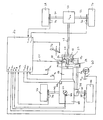
Bei der in der Figur dargestellten Antriebsanordnung wird der Planetenradträger 10 eines Zwischenachsausgleichsgetriebes 12 über die Antriebswelle 14 und ein Geschwindigkeitswechselgetriebe 16 von einer Brennkraftmaschine 18 angetrieben. Durch die Planetenräder 20 werden das Zentralrad 22 und das äußere Hohlrad 24 des Zwischenachsausgleichsgetriebes 12 angetrieben. Zur Sperrung des Zwischenachsausgleichsgetriebes 12 können das Zentralrad 22 und das äußere Hohlrad 24 des Zwischenachsausgleichsgetriebes 12 durch eine von einer Steuereinheit 26 über eine Steuerleitung 28 gesteuerte Zwischenachsausgleichsgetriebesperre 30 drehfest miteinander verbunden werden. Das Zentralrad 22 treibt über eine Hohlwelle 32 und über eine drehfeste Verbindung 34 die vordere Abtriebswelle 36 des Zwischenachsausgleichsgetriebes 12 an. Diese vordere Abtriebswelle 36 treibt über ein vorderes Achsausgleichsgetriebe 38 und über vordere Gelenkwellen 40 und 42 die Vorderräder 44 und 46 eines mit der dargestellten Antriebsanordnung ausgerüsteten Kraftfahrzeuges an. Das äußere Hohlrad 24 des Zwischenachsausgleichsgetriebes 12 treibt über dessen hintere Abtriebswelle 48, über das hintere Achsausgleichsgetriebe 50 und über die hinteren Gelenkwellen 52 und 54 die Hinterräder 56 und 58 des Kraftfahrzeuges an.In the drive arrangement shown in the figure, the
Wesentliche Merkmale der in der Figur dargestellten Antriebsanordnung sind einerseits, daß die Achsausgleichsgetriebeübersetzungen iVA und iHA und/oder die Zwischenachsausgleichsgetriebeübersetzung und/oder das Verhältnis der Reifengrößen zwischen den Vorderrädern 44 und 46 und den Hinterrädern 56 und 58 des Kraftfahrzeuges derart festgelegt sind, daß sich bei ungesperrtem Zwischenachsausgleichsgetriebe 12 zwischen dessen vorderer Abtriebswelle 36 und dessen hinterer Abtriebswelle 48 im normalen, weitgehend schlupffreien Fahrbetrieb des Kraftfahrzeuges eine kleine definierte Drehzahldifferenz einstellt, und andererseits, daß die Zwischenachsausgleichsgetriebesperre 30 durch die elektronische Steuereinheit 26, die durch einen Mikrocomputer gebildet sein kann, hinsichtlich ihres Sperrgrades steuerbar ist. Bei der in der Figur dargestellten Antriebsanordnung soll im normalen, weitgehend schlupffreien Fahrbetrieb des Kraftfahrzeuges die Drehzahl der vorderen Abtriebswelle 36 des ungesperrten Zwischenachsausgleichsgetriebes 12 größer sein als die Drehzahl der hinteren Abtriebswelle 48 des Zwischenachsausgleichsgetriebes 12. Die Drehzahldifferenz soll dabei vorzugsweise 2% der Drehzahl der vorderen Abtriebswelle 36 bzw. der hinteren Abtriebswelle 48 betragen.Essential features of the drive arrangement shown in the figure are, on the one hand, that the axle differential gear ratios i VA and i HA and / or the intermediate axle differential gear ratio and / or the ratio of the tire sizes between the
Bei der dargestellten Antriebsanordnung soll die Steuerung des Sperrgrades der Zwischenachsausgleichsgetriebesperre 30 in Abhängigkeit vom Lenkwinkel αL des Kraftfahrzeuges derart erfolgen, daß der Sperrgrad der Zwischenachsausgleichsgetriebesperre 30 mit zunehmendem Lenkwinkel αL kontinuierlich angehoben wird. Dies hat zur Folge, daß mit zunehmendem Lenkwinkel αL der Anteil des Antriebsdrehmoments auf die Vorderräder 44 und 46 beim Durchfahren von Kurven abnimmt und der Anteil des Antriebsdrehmoments auf die Hinterräder 56 und 58 zunimmt. Auf diese Weise ist ein gezieltes Übersteuern des Kraftfahrzeuges in Kurven möglich. Wenn am Kurvenausgang der Lenkwinkel αL wieder gegen null geht (Geradeausfahrt), wird mit abnehmendem Lenkwinkel αL der Sperrgrad der Zwischenachsausgleichsgetriebesperre 30 wieder kontinuierlich auf den Wert null verringert. Dies bedeutet, daß sich bei Geradeausfahrt des Kraftfahrzeuges wieder die konstruktiv vorgegebene Antriebsdrehmomentverteilung zwischen den Vorderrädern 44 und 46 und den Hinterrädern 56 und 58 einstellt. Der Lenkwinkel αL wird durch einen Lenkwinkelsensor 60 erfaßt. Dieser kann beispielsweise bei Verwendung einer in der Figur nicht dargestellten Zahnstangenlenkung an derem Gehäuse angeordnet sein und die Stellung der im Gehäuse verschiebbaren Zahnstange abtasten und daraus ein den eingestellten Lenkwinkel αL anzeigendes Lenkwinkelsignal liefern, das der elektronischen Steuereinheit 26 zugeführt wird.In the drive arrangement shown, the degree of locking of the intermediate axle
Neben dem Lenkwinkel αL stellt die jeweilige von der Brennkraftmaschine 18 abgegebene Antriebsleistung eine Kenngröße für die Steuerung des Sperrgrades der Zwischenachsausgleichsgetriebesperre 30 dar. Bei der in der Figur dargestellten Antriebsanordnung soll insbesondere bei Kurvenfahrt des Kraftfahrzeuges der Sperrgrad der Zwischenachsausgleichsgetriebesperre 30 mit zunehmender von der Brennkraftmaschine 18 des Kraftfahrzeuges jeweils abgegebenen Antriebsleistung verringert werden. Damit wird erreicht, daß mit zunehmender von Brennkraftmaschine 18 abgegebenen Antriebsleistung beim Durchfahren von Kurven der auf die Vorderräder 44 und 46 übertragene Anteil des Antriebsdrehmoments zunimmt. Es wird dadurch ein verstärker Vorderradantrieb erreicht, der das Fahrverhalten des Kraftfahrzeuges in Richtung "untersteuernd" beeinflußt. Die von der Brennkraftmaschine 18 jeweils abgegebene Antriebsleistung wird von der Steuereinheit 26 errechnet. Als Parameter dafür erhält die Steuereinheit 26 die von einem Drehzahlaufnehmer 62 erfaßte Brennkraftmaschinendrehzahl nMot, den von einem Drosselklappenwinkelsensor 64 aufgeommenen Drosselklappenwinkel αD und den von einem im Saugrohr der Brennkraftmaschine 18 angeordneten Drucksensor 66 erfaßten Saugrohrunterdruck pS.In addition to the steering angle α L , the respective drive power output by the
Schließlich stellt die Fahrgeschwindigkeit des Kraftfahrzeuges noch eine dritte Kenngröße für die Steuerung des Sperrgrades der Zwischenachsausgleichsgetriebsperre 30 dar. Bei der in der Figur dargestellten Antriebsanordnung wird der Sperrgrad der Zwischenachsausgleichsgetriebesperre 30 insbesondere bei Kurvenfahrt des Kraftfahrzeuges mit zunehmender Fahrgeschwindigkeit des Kraftfahrzeuges verringert. Dies bedeutet, daß sich mit zunehmender Fahrgeschwindigkeit des Kraftfahrzeuges in Kurvenfahrt die konstruktiv vorgegebene Antriebsdrehmomentverteilung zwischen den Vorderrädern 44 und 46 und den Hinterrädern 56 und 58 einstellt, wodurch das Fahrverhalten des Kraftfahrzeuges in Kurven mit zunehmender Fahrgeschwindigkeit in Richtung "neutral" bzw. "untersteuernd" beeinflußt wird. Die Fahrgeschwindigkeit des Kraftfahrzeuges wird von der Steuereinheit 26 aufgrund der über die Drehzahlaufnehmer 68, 70, 72 und 74 erfaßten Raddrehzahlen nVL, nVR, nHL und nHR berechnet.Finally, the driving speed of the motor vehicle represents a third parameter for controlling the degree of locking of the interaxle
Um eine Verspannung des Antriebsstranges im Rangierbetrieb des Kraftfahrzeuges zu verhindern, wird der Sperrgrad der Zwischenachsausgleichsgetriebesperre 30 auf seinen minimalen Wert verringert, wenn die Fahrgeschwindigkeit des Kraftfahrzeuges einen vorgegebenen Grenzwert, beispielsweise 10 km/h unterschreitet.In order to prevent tensioning of the drive train in the maneuvering mode of the motor vehicle, the degree of locking of the intermediate axle
Wie vorstehend dargelegt, dient die dargestellte Antriebsanordnung zur Veränderung der Antriebsdrehmomentverteilung zwischen den Vorderrädern 44 und 46 und den Hinterrädern 56 und 58 in Abhängigkeit der Kenngrößen Lenkwinkel αL, Antriebsleistung der Brennkraftmaschine 18 und Fahrgeschwindigkeit des Kraftfahrzeuges. Die dargestellte Antriebsanordnung dient darüber hinaus auch als Rückrollbremse beim Anfahren des Kraftfahrzeuges am Berg. Damit eine solche Rückrollbremse von der Steuereinheit 26 automatisch aktiviert bzw. deaktiviert werden kann, muß zu den bereits erfaßten Kenngrößen zusätzlich noch der Kupplungspedalweg KPW, die Betätigung der Bremse (BS) und die Stellung des Schalthebels 76 des Geschwindigkeitswechselgetriebes 16 erfaßt werden. Die Rückrollbremse wird aktiviert, d.h. der Sperrgrad der Zwischenachsausgleichsgetriebesperre 30 wird auf den maximalen Wert angehoben, wenn gleichzeitig die über die Raddrehzahlen nVL, nVR, nHL und nHR ermittelte Fahrgeschwindigkeit des Kraftfahrzeuges null, die Kraftfahrzeugbremse betätigt, die Brennkraftmaschinendrehzahl nMot. gleich der Leerlaufdrehzahl, der Drosselklappenwinkel αD gleich dem Drosselklappenwinkel im Leerlauf der Brennkraftmaschine 18, kein bzw. der erste Gang des Geschwindigkeitswechselgetriebes 16 des Kraftfahrzeuges eingelegt und die Kraftfahrzeugkupplung ausgerückt ist. Beim Anfahren des Kraftfahrzeuges wird die Rückrollbremse wieder deaktiviert, d.h. der Sperrgrad der Zwischenachsausgleichsgetriebesperre 30 wird auf den minimalen Wert verringert. Dies erfolgt, wenn gleichzeitig die ermittelte Fahrgeschwindigkeit des Kraftfahrzeuges größer null ist, der Drosselklappenwinkel αD von dem Drosselklappenwinkel im Leerlauf der Brennkraftmaschine 18 abweicht, die Brennkaftmaschinendrehzahl nmot größer als die Leerlaufdrehzahl ist und die Kraftfahrzeugkupplung eingerückt wird. Durch die vorstehend genannten Parameter kann sowohl das Anhalten des Kraftfahrzeuges als auch der Anfahrvorgang des Kraftfahrzeuges eindeutig identifiziert werden, so daß die Steuerung der Zwischenachsausgleichsgetriebesperre 30 von der Steuereinheit 26 automatisch erfolgen kann. Diese Rückrollbremse beruht auf dem Grundgedanken, daß sich die Vorderräder 44 und 46 gegenüber den Hinterrädern 56 und 58 aufgrund der zwischen vorderer Abtriebswelle 36 und hinterer Abtriebswelle 48 des Zwischenachsausgleichsgetriebes 12 gewählten Drehzahldifferenz verspannen, wenn die Zwischenachsausgleichsgetriebesperre 30 betätigt ist.As explained above, the drive arrangement shown serves to change the drive torque distribution between the
Claims (18)
characterised in that the differential axle gear transmission ratios (iVA, iHA) and/or the intermediate differential axle gear transmission ratio and/or the ratio of the tyre sizes of the front and rear wheels (44, 46, 56, 58) of the motor vehicle are fixed in such a way that when the intermediate differential axle gear (12) is unlocked a small, defined difference of rotation rate is established between its front and its rear drive-output shafts (36, 48) in the normal, largely slip-free driving operation of the motor vehicle, and in that the intermediate differential axle gear lock (30) is controllable, as regards its degree of locking, by means of a control unit (26).
Applications Claiming Priority (2)
| Application Number | Priority Date | Filing Date | Title |
|---|---|---|---|
| DE19873722205 DE3722205A1 (en) | 1987-07-04 | 1987-07-04 | DRIVE ARRANGEMENT FOR A MOTOR VEHICLE |
| DE3722205 | 1987-07-04 |
Publications (3)
| Publication Number | Publication Date |
|---|---|
| EP0298397A2 EP0298397A2 (en) | 1989-01-11 |
| EP0298397A3 EP0298397A3 (en) | 1989-04-26 |
| EP0298397B1 true EP0298397B1 (en) | 1991-04-24 |
Family
ID=6330948
Family Applications (1)
| Application Number | Title | Priority Date | Filing Date |
|---|---|---|---|
| EP88110574A Expired - Lifetime EP0298397B1 (en) | 1987-07-04 | 1988-07-01 | Motor vehicle drive arrangement |
Country Status (3)
| Country | Link |
|---|---|
| EP (1) | EP0298397B1 (en) |
| DE (2) | DE3722205A1 (en) |
| ES (1) | ES2022538B3 (en) |
Families Citing this family (12)
| Publication number | Priority date | Publication date | Assignee | Title |
|---|---|---|---|---|
| DE3908091A1 (en) * | 1989-03-13 | 1990-09-20 | Viscodrive Gmbh | LIMITED LOCKABLE SPROCKET DIFFERENTIAL |
| WO1990011908A1 (en) * | 1989-04-07 | 1990-10-18 | Zahnradfabrik Friedrichshafen Ag | Automatic locking device for a transfer gearbox |
| JPH03217336A (en) * | 1990-01-19 | 1991-09-25 | Mazda Motor Corp | Differential limit device for vehicle |
| DE4111615A1 (en) * | 1991-04-10 | 1992-10-15 | Daimler Benz Ag | Motor vehicle with central torque splitter for all wheel drive - providing uneven drive speeds for both axles with faster driven shaft carrying larger torque fraction |
| US5809443A (en) * | 1994-12-09 | 1998-09-15 | Ford Motor Company | Four-wheel drive transfer case controller with compensation for tires with different diameters |
| DE19706720A1 (en) * | 1996-04-06 | 1997-10-09 | Volkswagen Ag | Controlling coupling between front and rear axles of motor vehicle with four wheel drive |
| US5954778A (en) * | 1996-11-26 | 1999-09-21 | Ford Global Technologies, Inc. | Four-wheel drive transfer case controller with torque decrement strategy |
| US6047231A (en) * | 1997-06-06 | 2000-04-04 | Ford Global Technologies, Inc. | Four wheel drive transfer case controller compatible with a spare tire |
| US5979584A (en) * | 1997-07-25 | 1999-11-09 | Ford Global Technologies, Inc. | Four-wheel drive transfer case controller |
| DE10248090B4 (en) * | 2002-10-15 | 2012-08-09 | Volkswagen Ag | Method and device for controlling the drive of a motor vehicle |
| GB0423677D0 (en) * | 2004-10-25 | 2004-11-24 | Prodrive 2000 Ltd | Improved four wheel drive system |
| DE102010009665B4 (en) * | 2010-02-27 | 2017-08-03 | Bayerische Motoren Werke Aktiengesellschaft | Method for controlling the torque of a drive motor in a motor vehicle |
Family Cites Families (7)
| Publication number | Priority date | Publication date | Assignee | Title |
|---|---|---|---|---|
| US3748928A (en) * | 1971-09-20 | 1973-07-31 | Borg Warner | Control system for mutiple driving axle vehicle |
| JPS61143227A (en) * | 1984-12-18 | 1986-06-30 | Nissan Motor Co Ltd | Vehicle driving device |
| DE3507490C1 (en) * | 1985-03-02 | 1986-03-13 | Dr.Ing.H.C. F. Porsche Ag, 7000 Stuttgart | Locking system for a four-wheel drive motor vehicle |
| DE3516982C1 (en) * | 1985-05-10 | 1986-06-26 | Audi AG, 8070 Ingolstadt | All-wheel drive motor vehicle |
| JPS6231529A (en) * | 1985-08-05 | 1987-02-10 | Nissan Motor Co Ltd | Drive force distribution control device for four wheel drive vehicle |
| US4773500A (en) * | 1985-09-13 | 1988-09-27 | Nissan Motor Co., Ltd. | Driving torque distribution control system for 4WD vehicle |
| US4645029A (en) * | 1985-11-05 | 1987-02-24 | Toyota Jidosha Kabushiki Kaisha | Four-wheel vehicle drive system |
-
1987
- 1987-07-04 DE DE19873722205 patent/DE3722205A1/en not_active Withdrawn
-
1988
- 1988-07-01 DE DE8888110574T patent/DE3862533D1/en not_active Expired - Lifetime
- 1988-07-01 EP EP88110574A patent/EP0298397B1/en not_active Expired - Lifetime
- 1988-07-01 ES ES88110574T patent/ES2022538B3/en not_active Expired - Lifetime
Also Published As
| Publication number | Publication date |
|---|---|
| DE3722205A1 (en) | 1989-01-12 |
| DE3862533D1 (en) | 1991-05-29 |
| EP0298397A3 (en) | 1989-04-26 |
| ES2022538B3 (en) | 1991-12-01 |
| EP0298397A2 (en) | 1989-01-11 |
Similar Documents
| Publication | Publication Date | Title |
|---|---|---|
| DE3437435C2 (en) | Arrangement for controlling the power transmission of a four-wheel drive vehicle | |
| DE69935090T2 (en) | Torque distribution control system for a four-wheel drive vehicle | |
| DE3427725C2 (en) | ||
| DE102006026188B4 (en) | Method for distributing drive torque | |
| DE4243926C2 (en) | Torque-transfer device | |
| EP1203687B1 (en) | Variable torque distribution control system | |
| WO2006029684A1 (en) | Drive train and method for controlling a drive train | |
| EP1732777B1 (en) | Drive train for a motor vehicle | |
| DE3621225C1 (en) | Control device for temporarily switching a vehicle drive from a single-axis drive via a permanently driven vehicle axis to a two-axis drive | |
| DE3437436C2 (en) | Arrangement for controlling the power transmission of a four-wheel drive vehicle | |
| EP1837225A2 (en) | Vehicle all-wheel drive system | |
| EP0298397B1 (en) | Motor vehicle drive arrangement | |
| DE4213435A1 (en) | CONTROL SYSTEM FOR A DIFFERENTIAL | |
| DE102017204354B4 (en) | Method of operating an all-terrain vehicle with articulated steering | |
| DE3708193C2 (en) | ||
| EP2353916B1 (en) | Method for controlling a coupling assembly and power transmission for a motor vehicle | |
| DE3840004A1 (en) | MOTOR VEHICLE WITH OVER DIFFERENTIAL GEARBOX OD. DGL. DRIVED WHEELS | |
| DE60205489T2 (en) | VEHICLE WITH GEAR ASSEMBLY FOR A STEERING WHEEL PAIR | |
| DE3612189C2 (en) | ||
| DE19539670B4 (en) | Torque distribution control system | |
| EP1648729B1 (en) | Control device for an at least partially four-wheel driven motor vehicle | |
| DE3516982C1 (en) | All-wheel drive motor vehicle | |
| EP0339014B1 (en) | Differential gearing | |
| WO2005035296A1 (en) | Control system for an at least temporarily four-wheel driven motor vehicle | |
| DE102006008214A1 (en) | Wheel slip control system and method for controlling wheel movement of a vehicle |
Legal Events
| Date | Code | Title | Description |
|---|---|---|---|
| PUAI | Public reference made under article 153(3) epc to a published international application that has entered the european phase |
Free format text: ORIGINAL CODE: 0009012 |
|
| AK | Designated contracting states |
Kind code of ref document: A2 Designated state(s): DE ES FR GB IT SE |
|
| PUAL | Search report despatched |
Free format text: ORIGINAL CODE: 0009013 |
|
| AK | Designated contracting states |
Kind code of ref document: A3 Designated state(s): DE ES FR GB IT SE |
|
| 17P | Request for examination filed |
Effective date: 19891017 |
|
| 17Q | First examination report despatched |
Effective date: 19901004 |
|
| GRAA | (expected) grant |
Free format text: ORIGINAL CODE: 0009210 |
|
| AK | Designated contracting states |
Kind code of ref document: B1 Designated state(s): DE ES FR GB IT SE |
|
| ET | Fr: translation filed | ||
| GBT | Gb: translation of ep patent filed (gb section 77(6)(a)/1977) | ||
| REF | Corresponds to: |
Ref document number: 3862533 Country of ref document: DE Date of ref document: 19910529 |
|
| ITF | It: translation for a ep patent filed |
Owner name: STUDIO JAUMANN |
|
| PLBE | No opposition filed within time limit |
Free format text: ORIGINAL CODE: 0009261 |
|
| STAA | Information on the status of an ep patent application or granted ep patent |
Free format text: STATUS: NO OPPOSITION FILED WITHIN TIME LIMIT |
|
| 26N | No opposition filed | ||
| EAL | Se: european patent in force in sweden |
Ref document number: 88110574.6 |
|
| PGFP | Annual fee paid to national office [announced via postgrant information from national office to epo] |
Ref country code: ES Payment date: 19970704 Year of fee payment: 10 |
|
| PGFP | Annual fee paid to national office [announced via postgrant information from national office to epo] |
Ref country code: FR Payment date: 19970729 Year of fee payment: 10 |
|
| PG25 | Lapsed in a contracting state [announced via postgrant information from national office to epo] |
Ref country code: ES Free format text: LAPSE BECAUSE OF EXPIRATION OF PROTECTION Effective date: 19980702 |
|
| PG25 | Lapsed in a contracting state [announced via postgrant information from national office to epo] |
Ref country code: FR Free format text: LAPSE BECAUSE OF NON-PAYMENT OF DUE FEES Effective date: 19990331 |
|
| REG | Reference to a national code |
Ref country code: FR Ref legal event code: ST |
|
| PGFP | Annual fee paid to national office [announced via postgrant information from national office to epo] |
Ref country code: SE Payment date: 19990705 Year of fee payment: 12 |
|
| PG25 | Lapsed in a contracting state [announced via postgrant information from national office to epo] |
Ref country code: SE Free format text: LAPSE BECAUSE OF NON-PAYMENT OF DUE FEES Effective date: 20000702 |
|
| REG | Reference to a national code |
Ref country code: ES Ref legal event code: FD2A Effective date: 20010201 |
|
| EUG | Se: european patent has lapsed |
Ref document number: 88110574.6 |
|
| REG | Reference to a national code |
Ref country code: GB Ref legal event code: IF02 |
|
| PG25 | Lapsed in a contracting state [announced via postgrant information from national office to epo] |
Ref country code: IT Free format text: LAPSE BECAUSE OF NON-PAYMENT OF DUE FEES;WARNING: LAPSES OF ITALIAN PATENTS WITH EFFECTIVE DATE BEFORE 2007 MAY HAVE OCCURRED AT ANY TIME BEFORE 2007. THE CORRECT EFFECTIVE DATE MAY BE DIFFERENT FROM THE ONE RECORDED. Effective date: 20050701 |
|
| PGFP | Annual fee paid to national office [announced via postgrant information from national office to epo] |
Ref country code: DE Payment date: 20070822 Year of fee payment: 20 |
|
| PGFP | Annual fee paid to national office [announced via postgrant information from national office to epo] |
Ref country code: GB Payment date: 20070726 Year of fee payment: 20 |
|
| REG | Reference to a national code |
Ref country code: GB Ref legal event code: PE20 Expiry date: 20080630 |
|
| PG25 | Lapsed in a contracting state [announced via postgrant information from national office to epo] |
Ref country code: GB Free format text: LAPSE BECAUSE OF EXPIRATION OF PROTECTION Effective date: 20080630 |