EP0296645B1 - Procédé de compostage de matériaux organiques et appareil pour ce procédé - Google Patents
Procédé de compostage de matériaux organiques et appareil pour ce procédé Download PDFInfo
- Publication number
- EP0296645B1 EP0296645B1 EP88200825A EP88200825A EP0296645B1 EP 0296645 B1 EP0296645 B1 EP 0296645B1 EP 88200825 A EP88200825 A EP 88200825A EP 88200825 A EP88200825 A EP 88200825A EP 0296645 B1 EP0296645 B1 EP 0296645B1
- Authority
- EP
- European Patent Office
- Prior art keywords
- air
- heat
- heat exchanger
- used air
- fresh air
- Prior art date
- Legal status (The legal status is an assumption and is not a legal conclusion. Google has not performed a legal analysis and makes no representation as to the accuracy of the status listed.)
- Expired - Lifetime
Links
Images
Classifications
-
- A—HUMAN NECESSITIES
- A01—AGRICULTURE; FORESTRY; ANIMAL HUSBANDRY; HUNTING; TRAPPING; FISHING
- A01G—HORTICULTURE; CULTIVATION OF VEGETABLES, FLOWERS, RICE, FRUIT, VINES, HOPS OR SEAWEED; FORESTRY; WATERING
- A01G9/00—Cultivation in receptacles, forcing-frames or greenhouses; Edging for beds, lawn or the like
- A01G9/24—Devices or systems for heating, ventilating, regulating temperature, illuminating, or watering, in greenhouses, forcing-frames, or the like
- A01G9/247—Watering arrangements
-
- B—PERFORMING OPERATIONS; TRANSPORTING
- B01—PHYSICAL OR CHEMICAL PROCESSES OR APPARATUS IN GENERAL
- B01D—SEPARATION
- B01D53/00—Separation of gases or vapours; Recovering vapours of volatile solvents from gases; Chemical or biological purification of waste gases, e.g. engine exhaust gases, smoke, fumes, flue gases, aerosols
- B01D53/34—Chemical or biological purification of waste gases
- B01D53/74—General processes for purification of waste gases; Apparatus or devices specially adapted therefor
- B01D53/84—Biological processes
- B01D53/85—Biological processes with gas-solid contact
-
- C—CHEMISTRY; METALLURGY
- C05—FERTILISERS; MANUFACTURE THEREOF
- C05F—ORGANIC FERTILISERS NOT COVERED BY SUBCLASSES C05B, C05C, e.g. FERTILISERS FROM WASTE OR REFUSE
- C05F17/00—Preparation of fertilisers characterised by biological or biochemical treatment steps, e.g. composting or fermentation
- C05F17/10—Addition or removal of substances other than water or air to or from the material during the treatment
- C05F17/15—Addition or removal of substances other than water or air to or from the material during the treatment the material being gas
-
- C—CHEMISTRY; METALLURGY
- C05—FERTILISERS; MANUFACTURE THEREOF
- C05F—ORGANIC FERTILISERS NOT COVERED BY SUBCLASSES C05B, C05C, e.g. FERTILISERS FROM WASTE OR REFUSE
- C05F17/00—Preparation of fertilisers characterised by biological or biochemical treatment steps, e.g. composting or fermentation
- C05F17/60—Heating or cooling during the treatment
-
- C—CHEMISTRY; METALLURGY
- C05—FERTILISERS; MANUFACTURE THEREOF
- C05F—ORGANIC FERTILISERS NOT COVERED BY SUBCLASSES C05B, C05C, e.g. FERTILISERS FROM WASTE OR REFUSE
- C05F17/00—Preparation of fertilisers characterised by biological or biochemical treatment steps, e.g. composting or fermentation
- C05F17/90—Apparatus therefor
- C05F17/964—Constructional parts, e.g. floors, covers or doors
- C05F17/971—Constructional parts, e.g. floors, covers or doors for feeding or discharging materials to be treated; for feeding or discharging other material
- C05F17/979—Constructional parts, e.g. floors, covers or doors for feeding or discharging materials to be treated; for feeding or discharging other material the other material being gaseous
-
- F—MECHANICAL ENGINEERING; LIGHTING; HEATING; WEAPONS; BLASTING
- F24—HEATING; RANGES; VENTILATING
- F24V—COLLECTION, PRODUCTION OR USE OF HEAT NOT OTHERWISE PROVIDED FOR
- F24V99/00—Subject matter not provided for in other main groups of this subclass
-
- Y—GENERAL TAGGING OF NEW TECHNOLOGICAL DEVELOPMENTS; GENERAL TAGGING OF CROSS-SECTIONAL TECHNOLOGIES SPANNING OVER SEVERAL SECTIONS OF THE IPC; TECHNICAL SUBJECTS COVERED BY FORMER USPC CROSS-REFERENCE ART COLLECTIONS [XRACs] AND DIGESTS
- Y02—TECHNOLOGIES OR APPLICATIONS FOR MITIGATION OR ADAPTATION AGAINST CLIMATE CHANGE
- Y02A—TECHNOLOGIES FOR ADAPTATION TO CLIMATE CHANGE
- Y02A40/00—Adaptation technologies in agriculture, forestry, livestock or agroalimentary production
- Y02A40/10—Adaptation technologies in agriculture, forestry, livestock or agroalimentary production in agriculture
- Y02A40/25—Greenhouse technology, e.g. cooling systems therefor
-
- Y—GENERAL TAGGING OF NEW TECHNOLOGICAL DEVELOPMENTS; GENERAL TAGGING OF CROSS-SECTIONAL TECHNOLOGIES SPANNING OVER SEVERAL SECTIONS OF THE IPC; TECHNICAL SUBJECTS COVERED BY FORMER USPC CROSS-REFERENCE ART COLLECTIONS [XRACs] AND DIGESTS
- Y02—TECHNOLOGIES OR APPLICATIONS FOR MITIGATION OR ADAPTATION AGAINST CLIMATE CHANGE
- Y02A—TECHNOLOGIES FOR ADAPTATION TO CLIMATE CHANGE
- Y02A50/00—TECHNOLOGIES FOR ADAPTATION TO CLIMATE CHANGE in human health protection, e.g. against extreme weather
- Y02A50/20—Air quality improvement or preservation, e.g. vehicle emission control or emission reduction by using catalytic converters
-
- Y—GENERAL TAGGING OF NEW TECHNOLOGICAL DEVELOPMENTS; GENERAL TAGGING OF CROSS-SECTIONAL TECHNOLOGIES SPANNING OVER SEVERAL SECTIONS OF THE IPC; TECHNICAL SUBJECTS COVERED BY FORMER USPC CROSS-REFERENCE ART COLLECTIONS [XRACs] AND DIGESTS
- Y02—TECHNOLOGIES OR APPLICATIONS FOR MITIGATION OR ADAPTATION AGAINST CLIMATE CHANGE
- Y02P—CLIMATE CHANGE MITIGATION TECHNOLOGIES IN THE PRODUCTION OR PROCESSING OF GOODS
- Y02P20/00—Technologies relating to chemical industry
- Y02P20/10—Process efficiency
- Y02P20/129—Energy recovery, e.g. by cogeneration, H2recovery or pressure recovery turbines
-
- Y—GENERAL TAGGING OF NEW TECHNOLOGICAL DEVELOPMENTS; GENERAL TAGGING OF CROSS-SECTIONAL TECHNOLOGIES SPANNING OVER SEVERAL SECTIONS OF THE IPC; TECHNICAL SUBJECTS COVERED BY FORMER USPC CROSS-REFERENCE ART COLLECTIONS [XRACs] AND DIGESTS
- Y02—TECHNOLOGIES OR APPLICATIONS FOR MITIGATION OR ADAPTATION AGAINST CLIMATE CHANGE
- Y02P—CLIMATE CHANGE MITIGATION TECHNOLOGIES IN THE PRODUCTION OR PROCESSING OF GOODS
- Y02P20/00—Technologies relating to chemical industry
- Y02P20/141—Feedstock
- Y02P20/145—Feedstock the feedstock being materials of biological origin
-
- Y—GENERAL TAGGING OF NEW TECHNOLOGICAL DEVELOPMENTS; GENERAL TAGGING OF CROSS-SECTIONAL TECHNOLOGIES SPANNING OVER SEVERAL SECTIONS OF THE IPC; TECHNICAL SUBJECTS COVERED BY FORMER USPC CROSS-REFERENCE ART COLLECTIONS [XRACs] AND DIGESTS
- Y02—TECHNOLOGIES OR APPLICATIONS FOR MITIGATION OR ADAPTATION AGAINST CLIMATE CHANGE
- Y02W—CLIMATE CHANGE MITIGATION TECHNOLOGIES RELATED TO WASTEWATER TREATMENT OR WASTE MANAGEMENT
- Y02W30/00—Technologies for solid waste management
- Y02W30/40—Bio-organic fraction processing; Production of fertilisers from the organic fraction of waste or refuse
Definitions
- the invention relates to a method for aerobic, fermentative hydrolysis, in particular composting, of organic substances in a closed container according to the preamble of claim 1 and an apparatus for carrying out this method.
- DE-OS 34 01 889 discloses a method for aerobic, fermentative hydrolysis, in particular composting of organic substances in a closed container, in which fresh air is supplied to the organic substances and in which the exhaust air laden with heat and moisture is removed.
- the aerobic fermentation (rotting or composting) of biodegradable organic substances is linked to an aerobic climate (milieu).
- Components of an aerobic climate are: atmospheric air, humidity and thermal energy. Maintaining a climate that is adapted to the growth of aerobic organisms is the most important prerequisite for the fastest possible composting, particularly when it comes to waste composting.
- Composting uses open systems in which the question of the harmless removal of metabolic products has so far remained completely open. At most, a compost-covered earth filter was provided for exhaust air purification.
- the exhaust air is cooled so that the moisture condenses out.
- the exhaust air is then discharged to the atmosphere at ambient temperature and without moisture.
- the exhaust air cooled and dried in this way can then be discharged to the atmosphere at ambient temperature and without or with less moisture.
- the previously occurring odor nuisance is avoided.
- the exhaust air is not only cooled and dried before being released into the atmosphere, but is also cleaned by the water bath consisting of the condensate. The deodorizing antibacterial properties of the condensate are particularly great.
- the heat of the exhaust air is preferably transferred to the fresh air supplied through an air-air heat exchanger. This procedure is particularly energy-saving, since the fresh air that is to be supplied anyway is simultaneously used to cool the exhaust air. Furthermore, the fresh air is heated before it is fed to the organic substances, which results in further energy savings.
- the heat dissipated can be used immediately; but it can also be used by a heat pump.
- the exhaust air can be fed to an engine, preferably a steam engine, for generating mechanical and / or electrical energy.
- the condensate of moisture from the exhaust air can be used to irrigate plants. It can also be used to produce drinking water using ion exchangers, activated carbon filters or the like.
- the quantity of fresh air and thus the quantity of oxygen supplied per unit of time is preferably controlled as a function of the temperature and / or the oxygen content and / or the moisture in the organic substances and / or in the exhaust air after the outlet from the organic substances. This allows the process to be carried out optimally.
- the cooled and dried exhaust air can be passed into the atmosphere through a filter, preferably a sorption filter, in particular a sorption filter bed made of compost and / or activated carbon.
- filters for filtering the exhaust air are known per se. So far, however, the still warm and moist exhaust air has been passed through the filters. If the exhaust air is cooled and dried before it is passed through the filter, the main advantage is that it condenses out of the moist exhaust air Condensate is less polluted because it does not come into contact with the mostly organic filter materials. The condensate can therefore have drinking water quality or approximately drinking water quality.
- the heat exchange in the heat exchanger can take place directly at the interfaces between the fresh air drawn in and the exhaust air discharged.
- the heat of the exhaust air is therefore first fed to the heat transfer medium via a first heat exchanger.
- the heat transfer medium then releases the heat to the fresh air. This procedure enables the heat removal from the exhaust air on the one hand and the heat supply to the fresh air on the other hand to be carried out spatially separately.
- a portion of the exhaust air is preferably mixed in after the cooling and drying of the fresh air, preferably in the flow direction after the heat exchanger (if present). This reduces the fresh air requirement.
- the exhaust air or part of the exhaust air can be cooled by a cooling unit. This is particularly advantageous or necessary at higher outside temperatures, since then the temperature difference between the exhaust air and the fresh air may not be large enough.
- the object underlying the invention is further achieved by a device according to claim 13.
- the fermentation tank is closed on all sides.
- a heat exchanger is provided in which the heat of the exhaust air is given off to a heat transfer medium, so that the moisture in the exhaust air is condensed out. Because the fermentation container is closed, an uncontrolled escape of exhaust air is prevented.
- the exhaust air is cooled and dried in the heat exchanger. It can then be released into the atmosphere without any odors.
- a lower support surface for collecting the condensate is preferably provided in the heat exchanger, so that the cooled and dried exhaust air is passed through the condensate before being discharged into the atmosphere.
- the heat exchanger preferably consists of an air-air heat exchanger in which the heat transfer medium is the fresh air supplied.
- the heat exchanger can also be an air-water heat exchanger. It is possible to provide a heat pump to use the heat dissipated and / or a motor, preferably a steam motor, to generate mechanical and / or electrical energy from the heat of the exhaust air.
- An ion exchanger or activated carbon filter or the like is preferably provided for producing drinking water from the condensate of the moisture in the exhaust air.
- An advantageous development of the device according to the invention is characterized by one or more sensors for controlling the amount of fresh air supplied per unit of time and thus the amount of oxygen as a function of the temperature and / or the oxygen content and / or the moisture in the organic substances and / or in the exhaust air after Leaving the organic matter. This can optimize the process.
- a filter container with a filter preferably a sorption filter, in particular a sorption filter bed made of compost and / or activated carbon, is preferably provided for filtering the cooled and dried exhaust air, the filter mass preferably being stored in the filter container on air-permeable levels.
- the cooled and dried exhaust air is cleaned again before it is released into the atmosphere.
- a throttle valve is preferably arranged in the supply air line in the flow direction upstream of the heat exchanger and / or a throttle valve is arranged in the flow direction directly in front of the atmosphere in the flow direction. This allows the air flow to be controlled.
- the fresh air space is preferably formed around the fermentation space and the exhaust air-limiting surfaces are set up freely in this space.
- heat exchangers, condensate collectors, blowers, sorption filters, measuring and control devices form a compact, coherent unit which only has one air connection for the fresh air supply to the fermentation room and one exhaust air discharge from the fermentation room.
- An optionally operable control flap which closes the exhaust air line completely or partially, can be arranged in the exhaust air line, to which a bypass line connects.
- a cooling unit for cooling the exhaust air can be arranged in the bypass line, from which the exhaust air is fed to the heat exchanger.
- a closable and controllable ventilation flap for admixing cooled and dried exhaust air to the fresh air supplied to the fermentation tank is downstream in the direction of flow the heat exchanger provided. This reduces the need for fresh air.
- the heat transfer from the exhaust air on the one hand and to the fresh air on the other hand can be carried out at spatially separate locations.
- the invention allows the fermentation room to be air-conditioned in such a way that not only is the metabolic products displaced by fresh air, but that these products are converted into an environmentally compatible state and that at the same time the energy expenditure for climate control remains limited to the absolutely necessary size.
- the invention therefore takes into account the fact that the gases or vapors escaping from a fermenting mass as a result of displacement and / or flushing are to be sublimed or condensed out by heat removal, by transferring heat therefrom directly or indirectly via heat exchangers to the fresh air or optionally via a cooling circuit dissipated or used via a connected heat pump, thereby achieving an energy saving effect in addition to the condensation effect.
- the residues of environmentally harmful metabolic products still remaining in the exhaust air are then sorptively separated on sorptive bodies (e.g. biofilters, activated carbon filters, ion exchangers or silica gel).
- sorptive bodies e.g. biofilters, activated carbon filters, ion exchangers or silica gel.
- the examination of condensate showed that the quality of the condensate allows direct discharge into a receiving water.
- the water quality is comparable to that of cleaned wastewater from a sewage treatment plant.
- the fresh air supply is adapted to the biological oxygen consumption of the organisms, which is measured continuously. For an economically advantageous operation, it is advisable to regulate the fresh air supply between setpoints of 17 to 19 vol.% Atmospheric oxygen content in the fermenting waste mass.
- an advantageous embodiment of the invention is that the blower ensuring air transport sucks the fresh air through the heat exchanger and promotes it through the fermenting waste mass as well as heat exchanger and sorption filter into the free atmosphere.
- the device according to the invention with oxygen and temperature-dependent control can be connected to any externally ventilated aerobic fermenter, regardless of its size. There are no environmentally harmful metabolic products and the previous operating costs for the electrical energy for condensation through cooling are reduced to about a third.
- the condensation heat dissipated by cooling can be used via a heat pump.
- the performance figures to be achieved can reach values above 4.
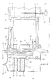
- the organic substances 1 are stored on an air-permeable level 2.
- the air box space 3 is located below the permeable level 2.
- the cavity 4 is located above the organic substances 1.
- the closed fermentation tank 5 is connected via a supply air pipe and an exhaust air pipe to a further tank which receives or forms the heat exchanger.
- the supply air line 12 is arranged, in which a closable and controllable throttle valve 11 is located.
- the vertical heat exchanger tubes 9, which open into an upper plate and extend to a lower plate are the vertical heat exchanger tubes 9, which open into an upper plate and extend to a lower plate. The air flowing in through the supply air line 12 thus flows through these heat exchanger tubes 9, but not through other areas of the heat exchanger container. After flowing through the heat exchanger tubes 9, the meanwhile heated Fresh air in area 17 of the heat exchanger tank. From there it is fed to the air box space 3 of the fermentation container 5 by the blower 6 via the fresh air line.
- the loaded exhaust air 8 passes from the cavity 4 via the exhaust air line 10 into the space 13 of the heat exchanger container surrounding the heat exchanger tubes 9.
- the condensate 14 collects on the lower support surface for the heat exchanger tubes 9. It can be drained from there through the valve 15.
- the valve 15 can be controlled by a float switch, as indicated by the dash-dotted arrow running from the valve 15 to the condensate 14.
- the condensate is collected behind the valve 15 in the direction of flow and can be passed on from there (see reference number 16).
- a control flap 34 is provided in the exhaust air line 10, which is pivotably mounted and can be closed and opened. This flap is normally in the solid position, so that the exhaust air is fed directly to the heat exchanger. If additional cooling of the exhaust air should be required, the control flap 34 is pivoted into the position shown in dashed lines.
- the exhaust air then flows completely or partially through the bypass line arranged parallel to the exhaust air line.
- a cooling unit 32, 33 is arranged in the heat exchanger tank, through which heat is extracted from the exhaust air flowing through the bypass line before further heat removal takes place in the actual air-air heat exchanger.
- a further valve 18 is provided for draining off condensate, which may have formed in this area of the heat exchanger tank.
- a filter container 29 is arranged directly next to the heat exchanger container.
- the heat exchanger container and the filter container 29 are connected to one another by a short pipeline 20.
- the upper cover of the filter container 29 has an exhaust pipe, in which a throttle valve 30 is provided for controlling the exhaust air flow.
- a drain valve 19 In the bottom of the filter container 29 there is a drain valve 19 for the discharge of any condensate formed.
- the filter container 29 is connected via the line 24 to the lower part of the heat exchanger container which lies outside the actual heat exchanger.
- a closable and openable control flap is located in the pipeline 24.
- Heat exchangers, condensate collectors, blowers, sorption filters, measuring and control devices form a compact, coherent unit which has only one air connection 12 for the fresh air supply to the fermentation room 5 and one exhaust air discharge 25 from the fermentation room 5. It is also possible to introduce fresh air into the circuit via a bypass without this fresh air being passed through the heat exchanger beforehand; this possibility is not shown in the drawing.
- the device has a probe for determining the climatic parameters. This probe is located in the fermentation container 5 and ends within the organic substances 1.
- a membrane pump 31 allows an air sample to be taken from the interior of the organic substances 1 and fed to an oxygen and / or temperature measuring device 27. The latter can control or regulate the speed of the blower 6, as indicated by the double dash-dotted line between the measuring device 27 and the blower 6.
- the entire device can be connected directly to waste containers, composting boxes, bioreactors, bio-cell reactors and / or animal stalls.
- the device additionally has a heat exchanger (35) for connection to a cooler and / or a heat pump; this additional heat exchanger 35 is only indicated in the drawing.
- the fresh air 26 is sucked in through the heat exchanger tubes 9 and blown into the air box space 3 via the connecting piece 17 through the blower 6 via the fresh air socket 12 with protective hood and throttle valve 11.
- the heated fresh air then flows through the openings in the base 2 into the mass 1 to be fermented aerobically and, on the path 7, releases the resulting metabolic products water, carbon dioxide, heat, vapors and gases and releases them via the outlet opening 8 from the cavity 4. Thereafter, the laden exhaust air 8 passes through the connection 10 into the space 13 separated from the fresh air.
- the air cleaned in this way then enters the space 29 via the connection 20, in which the sorptively acting biofilter mass 22 is stored on air-permeable levels 21, on the surfaces of which organisms convert the sorptively absorbed particles by fermentation or incorporate them into their bodies.
- the exhaust air (23) cleaned in this way exits freely into the atmosphere via connection piece 30 with throttle valve and cover hood.
- the metabolic products 14 of the exhaust air removed from the mass 1, which have become liquid as a result of condensation, are introduced via a condensate drain 15 in biologically cleaned wastewater quality.
- dehumidified exhaust air with a sufficient oxygen content in the circuit can be returned to the fermenter 5, or fresh air can be mixed into the air stream without heating.
- the fan 6 is switched on and off via the values for oxygen and temperature measured with the lance 27.
- the values of 17 to 20 vol.% Oxygen and a minimum decontamination temperature of greater than 50 C are used as a guideline.
- the oxygen content is determined using an electrochemical liquid cell consisting of an electrolyte and two metal electrodes that are connected to an electronic conversion device. An air sample is taken from the inside of the mass 1 by a diaphragm pump 31 and fed to the oxygen or temperature measuring device. In this way, the cheapest climate adapted to the biological metabolism can be created.
- the operating modes according to 1. and / or 2. should be selected if biologically generated heat and / or condensate cannot be used. If heat energy and / or condensate can be used, the heat exchanger 35 is connected to a heat pump. The further air flow corresponds to the version already described under 1.
Claims (25)
Applications Claiming Priority (2)
| Application Number | Priority Date | Filing Date | Title |
|---|---|---|---|
| DE3711230 | 1987-04-03 | ||
| DE3711230 | 1987-04-03 |
Publications (2)
| Publication Number | Publication Date |
|---|---|
| EP0296645A1 EP0296645A1 (fr) | 1988-12-28 |
| EP0296645B1 true EP0296645B1 (fr) | 1992-03-25 |
Family
ID=6324777
Family Applications (2)
| Application Number | Title | Priority Date | Filing Date |
|---|---|---|---|
| EP88200825A Expired - Lifetime EP0296645B1 (fr) | 1987-04-03 | 1988-04-05 | Procédé de compostage de matériaux organiques et appareil pour ce procédé |
| EP19880903231 Expired - Lifetime EP0322424B1 (fr) | 1987-04-03 | 1988-04-05 | Procede pour le compostage de substances organiques et dispositif permettant la mise en uvre de ce procede |
Family Applications After (1)
| Application Number | Title | Priority Date | Filing Date |
|---|---|---|---|
| EP19880903231 Expired - Lifetime EP0322424B1 (fr) | 1987-04-03 | 1988-04-05 | Procede pour le compostage de substances organiques et dispositif permettant la mise en uvre de ce procede |
Country Status (7)
| Country | Link |
|---|---|
| EP (2) | EP0296645B1 (fr) |
| AT (1) | ATE74118T1 (fr) |
| AU (1) | AU1626588A (fr) |
| DE (2) | DE3869584D1 (fr) |
| ES (1) | ES2032533T3 (fr) |
| GR (1) | GR3004147T3 (fr) |
| WO (1) | WO1988007507A1 (fr) |
Families Citing this family (22)
| Publication number | Priority date | Publication date | Assignee | Title |
|---|---|---|---|---|
| US4961763A (en) * | 1989-04-19 | 1990-10-09 | Space Biospheres Venture | Indoor air purifier |
| DE3923641A1 (de) * | 1989-07-17 | 1991-01-24 | Passavant Werke | Verfahren zur aerob-thermischen kompostierung von organischen abfaellen |
| DE3925905A1 (de) * | 1989-08-04 | 1991-02-28 | Hermann Hofmann | Verfahren und vorrichtung zur aeroben, fermentativen hydrolyse, insbesondere zur kompostierung von organischen stoffen |
| DE3935249C2 (de) * | 1989-10-23 | 1993-09-30 | Hermann Hofmann | Verfahren und Vorrichtung zum Entfernen von Wasser aus Gülle |
| NO175896C (no) * | 1991-09-20 | 1994-12-28 | Svein Tegle | Fremgangsmåte til nöytralisering og gjenvinning av gasser som frigjöres ved våtkompostering av husdyrgjödsel og kloakkslam og lignende masser, samt anlegg til utförelse av fremgangsmåten. |
| EP0541184B1 (fr) * | 1991-11-08 | 1998-03-18 | Veluwse Afval Recycling B.V. | Procédé de compostage de matériaux organiques et appareil pour ce procédé |
| DE4215269C3 (de) * | 1992-05-09 | 1999-02-11 | Grabbe Klaus | Kompostierungsanlage mit einem Belüftungssystem für geschlossene Rotteanlagen |
| TW313915U (en) * | 1993-04-27 | 1997-08-21 | Hitachi Ltd | Solid organic waste processing apparatus |
| JPH07124538A (ja) * | 1993-11-01 | 1995-05-16 | Hitachi Ltd | 固形有機廃棄物の処理装置 |
| DE4322688C2 (de) * | 1993-07-07 | 1995-07-27 | Herhof Umwelttechnik Gmbh | Verfahren zur Kompostierung von organischen Stoffen, insbesondere Abfällen |
| AU5465494A (en) * | 1993-11-11 | 1995-05-29 | Klaus Grabbe | Process and device for biological treatment of substances and/or substance mixtures in closed rotting reactors |
| DK136193A (da) * | 1993-12-06 | 1995-06-28 | Vagn Bislev | Komposteringsanlæg til organisk affald, samt fremgangsmåde ved kompostering af sådant affald |
| DE4412890A1 (de) * | 1994-04-14 | 1995-10-19 | Herhof Umwelttechnik Gmbh | Verfahren und Vorrichtung zur Reinigung von Wasser, insbesondere aus einem Kompostierungsprozeß |
| FR2720389B1 (fr) * | 1994-05-20 | 1996-08-14 | Philippe Peultier | Procédé et installation de déshydratation par compostage d'effluents liquides. |
| CH689376A5 (de) * | 1995-01-27 | 1999-03-31 | Frank Rindelaub | Nachreinigungsvorrichtung fuer Abgasfiltertuerme. |
| DE19740310A1 (de) * | 1997-09-13 | 1999-04-01 | Octapharma Ag | Peptid mit Affinität zu Gerinnungsfaktor VIII |
| AT408984B (de) * | 1997-10-17 | 2002-04-25 | Mut Maschinen Umwelttechnik | Kompostierungssystem |
| DE102005026587A1 (de) * | 2005-05-27 | 2006-11-30 | Kaufmann, Jürgen | Verfahren und Vorrichtung zur Aufbereitung von Biogas oder Faulgas |
| FR2896243B1 (fr) * | 2006-01-13 | 2008-11-07 | Vinci Environnement Soc Par Ac | Procede de compostage ou de stabilisation de matieres organiques et installation pour la mise en oeuvre dudit procede. |
| AR071891A1 (es) | 2008-05-30 | 2010-07-21 | Imclone Llc | Anticuerpos humanos anti-flt3 (receptor tirosina cinasa 3 tipo fms humano) |
| US9895726B1 (en) | 2016-07-27 | 2018-02-20 | Whirlpool Corporation | Method for cleaning a food waste recycling bin of a food waste recycling appliance |
| US10000429B2 (en) | 2016-03-09 | 2018-06-19 | Whirlpool Corporation | Method and apparatus for operating a composter device |
Family Cites Families (10)
| Publication number | Priority date | Publication date | Assignee | Title |
|---|---|---|---|---|
| DE2319171A1 (de) * | 1973-04-16 | 1974-10-31 | Dag Romell | Verfahren und vorrichtung zum verbessern des vermoderungsverlaufes in einer anlage zur vermoderung organischer abfallprodukte |
| DE2558255B2 (de) * | 1975-12-23 | 1979-08-23 | Gebrueder Weiss Kg, 6340 Dillenburg | Verfahren zur Nutzung der beim Kompostieren von organischen Abfällen und/oder Klärschlamm anfallenden Abluft |
| DE2809344C2 (de) * | 1978-03-03 | 1984-01-19 | Gebrüder Weiss KG, 6340 Dillenburg | Verfahren zum Kompostieren von organischen Abfällen und/oder Klärschlamm |
| DE3040543A1 (de) * | 1980-10-28 | 1982-05-27 | Karl-Ernst 6601 Klarenthal Schnorr | Vorrichtung zur nutzung von verrottungswaerme |
| DE3043062A1 (de) * | 1980-11-12 | 1982-06-16 | Herwig 1000 Berlin Michel-Kim | Verfahren zur beschleunigung der humusbildung aus pflanzlichen und/oder tierischen stoffen o.dgl. materialien und vorrichtung zur durchfuehrung des verfahrens |
| DE3104769A1 (de) * | 1981-02-11 | 1982-09-16 | Ernst 7326 Heiningen Weichel | Verfahren und vorrichtung zur gewinnung nutzbarer waerme durch schnellverrottung bzw. kompostierung, insbesondere pflanzlicher abfallstoffe sowie stallmist |
| CH645333A5 (en) * | 1981-03-13 | 1984-09-28 | Buchs Utb Umwelttechnik Ag | Moist composting process for organic waste materials, for example sewage sludge, and apparatus for carrying out the process |
| DE3204471A1 (de) * | 1982-02-09 | 1983-08-18 | Otto 5270 Gummersbach Nockemann | Fermentation organischer stoffe zur waerme- und duengergewinnung |
| DE3414044A1 (de) * | 1983-12-16 | 1985-06-27 | Mannesmann Veba Umwelttechnik GmbH, 4690 Herne | Verfahren zur entfernung von verunreinigungen aus gasstroemen und filter zur durchfuehrung des verfahrens |
| DE3621252A1 (de) * | 1986-06-25 | 1988-01-07 | Hermann Hofmann | Verfahren und vorrichtung zur kompostierung von organischen haushalts- und gartenabfaellen mit nutzung der biologisch entstehenden stoffwechselprodukte |
-
1988
- 1988-04-05 AU AU16265/88A patent/AU1626588A/en not_active Abandoned
- 1988-04-05 EP EP88200825A patent/EP0296645B1/fr not_active Expired - Lifetime
- 1988-04-05 WO PCT/EP1988/000278 patent/WO1988007507A1/fr active IP Right Grant
- 1988-04-05 ES ES88200825T patent/ES2032533T3/es not_active Expired - Lifetime
- 1988-04-05 AT AT88903231T patent/ATE74118T1/de not_active IP Right Cessation
- 1988-04-05 DE DE8888903231T patent/DE3869584D1/de not_active Expired - Fee Related
- 1988-04-05 DE DE3811399A patent/DE3811399A1/de active Granted
- 1988-04-05 EP EP19880903231 patent/EP0322424B1/fr not_active Expired - Lifetime
-
1992
- 1992-03-26 GR GR910402242T patent/GR3004147T3/el unknown
Also Published As
| Publication number | Publication date |
|---|---|
| GR3004147T3 (fr) | 1993-03-31 |
| DE3811399A1 (de) | 1988-10-13 |
| DE3869584D1 (de) | 1992-04-30 |
| WO1988007507A1 (fr) | 1988-10-06 |
| EP0322424B1 (fr) | 1992-03-25 |
| DE3811399C2 (fr) | 1990-08-16 |
| ATE74118T1 (de) | 1992-04-15 |
| ES2032533T3 (es) | 1993-02-16 |
| EP0322424A1 (fr) | 1989-07-05 |
| AU1626588A (en) | 1988-11-02 |
| EP0296645A1 (fr) | 1988-12-28 |
Similar Documents
| Publication | Publication Date | Title |
|---|---|---|
| EP0296645B1 (fr) | Procédé de compostage de matériaux organiques et appareil pour ce procédé | |
| DE3637393C2 (fr) | ||
| DE4021868C3 (de) | Verfahren zur Kompostierung von Rottegut | |
| JP2000001387A (ja) | 環境保全型家畜排泄物の適正処理施設 | |
| DE2721048C2 (de) | Vorrichtung zur Reinigung von Geruchsstoffe enthaltende Abluft | |
| DE4334435C2 (de) | Verfahren zum Kompostieren von organischen Stoffen | |
| EP0458136B1 (fr) | Procédé de compostage de déchets | |
| DE4208390C2 (de) | Verfahren und Vorrichtung zur Abkühlung feuchter und warmer Abluft aus einem Kompostierungsprozeß | |
| CH645333A5 (en) | Moist composting process for organic waste materials, for example sewage sludge, and apparatus for carrying out the process | |
| EP1010680B1 (fr) | Système de compostage | |
| EP0633235B1 (fr) | Procédé et appareil de compostage de matériaux organiques en particulier des déchets | |
| DE69838713T2 (de) | Symbiose zwischen hallen und gewächshäusern | |
| EP0413992A2 (fr) | Procédé et appareil d'hydrolyse par fermentation aérobique en particulier pour compostage de matières organiques | |
| AT408984B (de) | Kompostierungssystem | |
| DE19641291C1 (de) | Verfahren zur biologisch-thermischen Behandlung von Abfällen | |
| EP1468977B1 (fr) | Procédé pour l'aération de compost | |
| JPH08510204A (ja) | 有機物を堆肥にする装置および方法 | |
| DE19513262C1 (de) | Verfahren zur Kompostierung von organischen Stoffen, insbesondere von Abfällen | |
| AT403549B (de) | Verfahren zur reinigung von abluft und abluftreinigungsanlage | |
| EP0859749B1 (fr) | Traitement bio-thermique de dechets | |
| DE19709965C2 (de) | Kompostierungssvorrichtung zum biologischen Abbau organischer Stoffe und ihre Verwendung | |
| EP0252069A2 (fr) | Appareil de traitement de boues résiduaires | |
| DE19955162A1 (de) | Verfahren zur Abfallbehandlung und Anlage zur Durchführung desselben | |
| DE19750908A1 (de) | Verfahren und Vorrichtung zur Kompostierung von Abfällen | |
| Wirsig | Air-Conditioned Microbes Work Faster |
Legal Events
| Date | Code | Title | Description |
|---|---|---|---|
| PUAI | Public reference made under article 153(3) epc to a published international application that has entered the european phase |
Free format text: ORIGINAL CODE: 0009012 |
|
| AK | Designated contracting states |
Kind code of ref document: A1 Designated state(s): ES GR |
|
| 17P | Request for examination filed |
Effective date: 19890309 |
|
| 17Q | First examination report despatched |
Effective date: 19910606 |
|
| GRAA | (expected) grant |
Free format text: ORIGINAL CODE: 0009210 |
|
| AK | Designated contracting states |
Kind code of ref document: B1 Designated state(s): ES GR |
|
| REG | Reference to a national code |
Ref country code: GR Ref legal event code: FG4A Free format text: 3004147 |
|
| PLBE | No opposition filed within time limit |
Free format text: ORIGINAL CODE: 0009261 |
|
| STAA | Information on the status of an ep patent application or granted ep patent |
Free format text: STATUS: NO OPPOSITION FILED WITHIN TIME LIMIT |
|
| REG | Reference to a national code |
Ref country code: ES Ref legal event code: FG2A Ref document number: 2032533 Country of ref document: ES Kind code of ref document: T3 |
|
| 26N | No opposition filed | ||
| PGFP | Annual fee paid to national office [announced via postgrant information from national office to epo] |
Ref country code: GR Payment date: 19970321 Year of fee payment: 10 |
|
| PGFP | Annual fee paid to national office [announced via postgrant information from national office to epo] |
Ref country code: ES Payment date: 19970416 Year of fee payment: 10 |
|
| PG25 | Lapsed in a contracting state [announced via postgrant information from national office to epo] |
Ref country code: ES Free format text: LAPSE BECAUSE OF EXPIRATION OF PROTECTION Effective date: 19980406 |
|
| PG25 | Lapsed in a contracting state [announced via postgrant information from national office to epo] |
Ref country code: GR Free format text: LAPSE BECAUSE OF NON-PAYMENT OF DUE FEES Effective date: 19980430 |
|
| REG | Reference to a national code |
Ref country code: ES Ref legal event code: FD2A Effective date: 20000301 |