EP0293516A1 - Dispositif pour assurer des espaces libres sur le côté entrée ou sortie du moyen de transport sur des convoyeurs à bande - Google Patents
Dispositif pour assurer des espaces libres sur le côté entrée ou sortie du moyen de transport sur des convoyeurs à bande Download PDFInfo
- Publication number
- EP0293516A1 EP0293516A1 EP87118533A EP87118533A EP0293516A1 EP 0293516 A1 EP0293516 A1 EP 0293516A1 EP 87118533 A EP87118533 A EP 87118533A EP 87118533 A EP87118533 A EP 87118533A EP 0293516 A1 EP0293516 A1 EP 0293516A1
- Authority
- EP
- European Patent Office
- Prior art keywords
- roller
- apron
- conveying means
- conveyor
- partial
- Prior art date
- Legal status (The legal status is an assumption and is not a legal conclusion. Google has not performed a legal analysis and makes no representation as to the accuracy of the status listed.)
- Granted
Links
Images
Classifications
-
- B—PERFORMING OPERATIONS; TRANSPORTING
- B65—CONVEYING; PACKING; STORING; HANDLING THIN OR FILAMENTARY MATERIAL
- B65G—TRANSPORT OR STORAGE DEVICES, e.g. CONVEYORS FOR LOADING OR TIPPING, SHOP CONVEYOR SYSTEMS OR PNEUMATIC TUBE CONVEYORS
- B65G21/00—Supporting or protective framework or housings for endless load-carriers or traction elements of belt or chain conveyors
Definitions
- the invention relates to a device for securing conveyor inlet or outlet-side openings between the peripheral region near the supporting frame of a deflection or feed or discharge roller or roller or guide and / or pressure roller or roller for the conveyor means of a belt conveyor, preferably in one - or multi-belt or belt design or designed as a plate or hinged belt conveyor, and the roller or roller near the front end of the supporting frame of the same and / or a support piece of the storage device for these roller (s) or roller (s) against accidental risks from accidental or unauthorized intervention in such an opening by means of a space between the circumferential area of the roller or roller close to the supporting frame and the edge of the supporting frame for the conveying means which is close to the roller or roller and which is at risk of access or its end face close to the roller or roller from the supporting frame side in the direction of the central longitudinal plane of the belt conveyor normal to the surface of the conveying material on the conveying material, bridging at least up to the associated side edge of the upper and / or lower run of the convey
- openings which are present in conveyors working in one plane, both in the area of the conveying material feed station and the conveying material dispensing station, regardless of whether the drive is via the feed roller or roller set or the output roller or roller set or but takes place via a separate drive roller or roller set arranged between the two, and in the case of articulated belt conveyors, in addition to these locations, also in the areas of the conveying means upstream and downstream of the deflection roller or roller set or from the hold-down roller or roller set in all cases, both in the area of the upper run and the lower run of the conveying means, undesirable possibilities for dropping or introducing dirt or foreign bodies into the interior of the support frame of the belt conveyor, where the risk of malfunctions and / or impairments in hygiene is hereby caused and appropriate maintenance or cleaning Measures with the corresponding dreaded operating downtimes become necessary after relatively short operating intervals.
- cover members for the openings at risk of access which, from the support frame side in the direction of the normal longitudinal plane of the belt conveyor towards the surface of the conveying material, the access space between the circumferential area of the relevant roll or support frame-near roll and the roll or roll near Extend the trailing edge of the support frame at least as far as the assigned side edge of the upper and / or lower run of the conveying means.
- cover members are held either on the support frame, in particular on a lateral longitudinal beam of the same, or on a support piece of the storage device for the roller or roller in question or, if appropriate, an entire set of rollers or rollers.
- the support width of this longitudinal beam profile is determined by the thickness of the support piece.
- the strength of the supporting pieces to be used therefore indirectly determines the cost price of the entire belt conveyor, in that an essential weight-determining component of the same, namely the pair of supporting frame longitudinal bars, is to be designed with a corresponding opening width of their profile cross-section.
- an essential weight-determining component of the same namely the pair of supporting frame longitudinal bars
- Support pieces which are slidably guided in the manner described in the sliding guide rails of the longitudinal frame profiles, which are open at the front, have their zone, subject to high stress levels, irrespective of whether they are manufactured as a subsequently machined welding flame separating part or stamped part or as a cast part or as a cast part projecting freely over the end face or edge of the longitudinal frame profile and adjoining the tail area enclosed by the longitudinal frame profile. It is precisely in this area that the cover member is required if it is provided fixed to the support piece. If such a cover member is releasably attached to the support piece, this cross section of the support piece is weakened in terms of material by the required fastening means.
- the invention is therefore based on the object to provide a possibility with simple and inexpensive means for belt conveyors of the generic type while avoiding the disadvantages of conventional safeguards for openings of the type described, regardless of the design of the supporting pieces of the storage device for the deflection or feed or discharge roller or role for the funding a common flow and return protection to be able to realize such access-prone openings against undesired or unauthorized intervention or the ingress of dirt or foreign bodies, in addition to guaranteeing increased security against deformations or damage during storage and possibly transportation to the place of use and saving labor and time in prefabricating the cover member and in particular with whose assembly and adjustment on the support piece, with the exclusion of additional manufacturing-related internal prestresses, enables a practical increase in the section modulus of the respective cover member-bearing support piece against deformations and thus a corresponding reduction in the material stresses occurring during operation, so overall an improved rigidity of the support piece despite the possibility of reducing the material thickness is achieved is, which benefits an improvement in the lightweight construction options of the entire support structure
- the cover member as at least the area of the roller or the roller close to the supporting frame on its side not leading the conveyor between the incoming and outgoing run of the same with only one movement or adjustment margin for this encompassing apron is designed.
- the cover member can be used as at least the area of the roller or the roller close to the supporting frame on its side not leading the conveying means, providing only a range of movement or adjustment for the upper strand of the conveying means below it only a range of movement or adjustment for the lower run of the conveying means can be formed above the apron engaging behind it.
- a proven alternative is characterized in that the cover member acts as at least the region of the deflecting roller used in the articulated region or the deflecting roller or hold-down roller or roller of the latter which is used in the region of the kink the conveying means leading side is not formed on an apron which only encompasses a range of movement or adjustment for this angular range with respect to the axis of rotation of the associated roller or roller.
- the invention provides that the cover member acts as at least the area near the support piece of the deflecting roller used in the articulated area or of the deflecting roller or hold-down roller or roller thereof not the conveying means leading side on an angle range corresponding to the complementary angle to the maximum bending angle of both length ranges of the conveying means or the supporting frame with respect to the Axis of rotation of the associated roller or roller apron is formed.
- the opening which is at risk of access is in each case only secured by a support piece of the bearing device on the inlet or outlet run side for the relevant roller or roller used in the kink area.
- such an embodiment of the invention offers the possibility, for the creation of the entire storage device assigned to either one strand of the conveying means or to both runs of the same, for the rollers or rollers or roller or roller sets involved in the articulated deflection of the conveying means with only one right and a left-hand version of the support pieces of this storage device, namely that these support pieces can be designed simply and inexpensively so that a right-hand version of the same is assigned to the inlet-side region of the conveying strand and a similar type of supporting piece is arranged opposite to the outlet-side strand area of the conveyor on the other side of the supporting frame.
- a proven special design of a device according to the invention for a belt conveyor in the form of an articulated conveyor with angularly adjustable length ranges of the conveying means and of the supporting frame carrying the latter is characterized in that the support piece of the storage device for the conveying means outlet and the conveying means inlet side for the deflecting roller or deflecting roller near the supporting frame or holding roller
- Each roll has a cover member in the form of an area of this roll or roll, at least close to the support piece, from its side not leading the conveying means on a partial apron which covers at least 180 ° corresponding angular range, taking into account a range of movement or adjustment for the conveying means, both of which Partial aprons are arranged offset to one another in the axial direction of the associated roller or roller.
- At least one of the aprons or partial aprons, preferably the apron or partial apron of the support piece of the storage device on the conveying device inlet side for the deflecting roller or deflecting roller or hold-down roller or hold-down roller used in the buckling area, can be in it in all belt conveyors in the form of an articulated conveyor have a ramp ramp inclined to the level of the conveyor.
- the ramp can preferably extend over at least part of the width of the assigned other partial apron in the axial direction of the assigned roller or roller. This provides a particularly good protection against, in particular, the ingress of dirt into the effective range of the kinematic members of the relevant strand deflection of the conveying means.
- the apron has a surface parallel to the direction of tension on the upper and / or lower side.
- the design can be appropriately made such that the apron or at least one of the partial aprons on the run side has a surface parallel to the tensioning direction of the associated conveyor area at a maximum articulation angle of both length regions of the conveyor or the support frame.
- the apron or at least one of the partial aprons on the run side diverges or at a maximum articulation angle of both length ranges of the conveying means or of the supporting frame for the tensioning direction of the assigned conveying area but has a converging inclined surface.
- an embodiment of the device according to the invention has also proven particularly useful, in which the apron or at least one of the partial aprons has a contour conforming to the roller or roller surface on its side near the roller or roller.
- this contour of the apron or at least one of the partial aprons deviates from the surface of the roller or roller on its side near the roller or roller.
- Such an apron can expediently have a larger distance from the roller or roller surface on its side near the roller or roller, between the end region near and below the end region or, in the case of belt conveyors of the articulated type, the strand near and the free end region of its surface near the roller or roller than these end regions have an adhering contour.
- both partial aprons can also expediently have one on the roller or roller side near the belt and the free end area of their roller or have an increasingly greater distance from the surface of the roll or the roll to maintain the contour.
- These special designs described serve in particular to expand the angle of attack of the axis or shaft of the associated roller or roller or of the associated roller and roller set in the case of inclined adjustment in order to compensate for the straight travel of the conveying means relative to the vertical central longitudinal plane of the conveyor.
- the advantageous effects sought by the invention are also achieved if the apron or partial apron is detachably fixed to the associated support piece of the storage device.
- the apron or partial apron is fixedly arranged on the associated support piece of the storage device. It can expediently be welded to the associated support piece of the storage device, for example by spot welding, or else riveted or glued.
- the apron or partial apron is molded, for example cast on, to the associated support piece of the storage device.
- the apron or partial apron extends over the free space between two corresponding supporting pieces of the storage device arranged on different supporting frame sides.
- the roller or roller axis or shaft assigned to the apron or partial apron can be kept adjustable relative to the apron or partial apron in the associated support piece or in the associated support pieces of the storage device.
- the supporting piece of the bearing device having the apron or partial apron can preferably have at least one elongated hole in which the associated roller or roller axis or shaft is held displaceably by means of a bearing holder.
- a particular universality of the possibility of adjusting the apron or partial apron relative to the assigned roller or roller or to the assigned roller or roller set the embodiment which, in the case of belt conveyors of the articulated type, with angularly adjustable length ranges of the conveying means and of the supporting frame carrying these and with these areas each assigned partial aprons of the storage device is used, characterized in that the supporting pieces having the partial aprons of the storage device each have at least one elongated hole, preferably oriented in the direction of the incoming and / or in the direction of the outgoing run of the conveying means, the elongated hole or at least one of the elongated holes of one support piece at least partially covering the elongated hole or at least one of the elongated holes of the other support piece and the associated roller or roller axis or shaft is held displaceably by means of a bearing bracket which passes through the overlapping elongated holes of the two support pieces.
- both of the last-mentioned embodiments of the invention also make it possible for the roller (s) or roller (s) to be inclined, if desired. relative to the vertical central longitudinal plane of the conveyor in order to influence the straight running of the conveyor.
- the invention not only the flexural and torsional rigidity of supporting members provided with cover members of storage devices for rollers or rollers or roller or roller sets of the type described in the introduction, particularly in their stress-sensitive areas, especially just outside the guide thereof in the free Improved profile opening of the associated support frame longitudinal spar, but also allows designs of such support pieces with a smaller wall thickness for a given load and thus enables significant weight savings over the entire conveyor length by reducing the lateral outreach of the associated support frame longitudinal spar profiles, always providing reliable common flow and return protection against unauthorized or unintentional intervention or the ingress of dirt or foreign bodies.
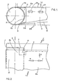
- the belt conveyor designated as a whole by 1 has a support frame designated in FIG. 2 by 2, which consists of one or more longitudinal spars arranged one behind the other in the longitudinal direction of the support frame and connected to one another in pairs and on each side a pair of support pieces 4 of storage devices for the axis or Shaft of a deflection or feed or discharge roller or roller or a set of such rollers or rollers is formed, of which a roller working as a deflection roller is shown in FIGS. 1 and 2 and is designated by 3.
- the support frame 2 has longitudinal bars designed as C-profiles, which are connected to each other in pairs opposite each other by cross-members and stiffened (not shown).
- the supporting frame 2 could also be integrally formed in the transverse direction by arranging a C-profile part, which supports the upper run 10a of the conveyor 10 from its underside, to form a supporting frame forming a conveyor belt with its base web parallel and its side webs parallel to the longitudinal plane of the supporting frame.
- a cover member 11 which is integrally formed in the form of an apron on the main body of the support member 4 so that it is only one Movement or adjustment space for the upper strand 10a of the conveyor 10 while below it extends to only one movement or adjustment space for the lower strand 10b of the conveyor 10 while above it in the axial direction of the axis or shaft 9 of the roller 3, as in FIGS. 1 and 2 shown.
- the apron 11 has on its side facing the upper run 10a of the conveying means 10 a surface 11a which is parallel to the direction of tension, namely parallel to the upper run 10a.
- the lower strand 10b of the conveyor by means of 10 facing side of the apron 11 is provided with a surface 11b which is inclined divergently with respect to the axis of rotation 9 of the associated roller 3, as can be seen from FIG. 1.
- This has the purpose of making it possible to change the angle of attack of the lower run 10b of the conveying means 10 relative to the roller 3, as indicated in FIG. 1 by two dash-dotted lines, of which the lower one has an operating adjustment of the lower run 10b of the conveying means 10 parallel to the upper run and the upper one an angularly changed operating position of the same symbolizes if this should prove necessary, for example, for reasons of changing the pretensioning of the conveying means 10 or the driving force in the area of the roller 3.
- the apron 11 has only such an extension in the direction of the axis 9 of the roller 3 that it engages over the area 3a of the support near the support piece so far that it engages under the edge area of the upper run 10a of the conveyor 10 near the support.
- the desired consequence of this is that, as can be seen in particular from FIG.
- the apron has the openings 7 and 8 between the peripheral area of the roller 3 near the supporting frame and the end of the supporting frame 2 and / or the supporting piece 4 of the bearing device for the roller 3 near the roller or roller, against the risk of accidents due to unintentional or unauthorized intervention or incidence or penetration of dirt or foreign bodies into the upper side Opening 7 as well as in the lower-side opening 8 reliably secured.
- the apron 11 has on its side facing the adjacent surface 3a of the roller 3 a surface 11c which is contoured to conform to this surface 3a.
- the apron 11 can also have such a shape that the distance to the roller surface 3a between its upper run and its lower run end area is greater than the distance in these end areas. This will always be preferable if the largest possible inclination angle of the roller axis 9 relative to the normal position shown in FIG. 2 to the vertical central longitudinal plane of the belt conveyor 1 is important, for example, in order to improve the straight running properties of the conveyor 10.
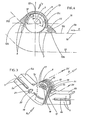
- FIG. 3 corresponds in principle to that according to FIG. 1, but with the areas of the outer piece 5 corresponding to the areas of the bearing support pieces 4 bearing the roller or roller axis or shaft according to FIGS. 1 and 2 3 are formed in the usual way by having a common bore for the passage of a pivot axis 9 to be carried out in a conventional manner and a circular arc slot 19 concentric with its center or axis of rotation, through which a screw element (not shown) reaches through in a conventional manner, by means of the outer piece 5 and inner piece 6 of this folding fitting in the angular assignment selected as the working position to each other.
- the outer piece 5 is similar to that 1 and 2 with guide strips and a fixing slot 5a between them and an outwardly extending side lug 20 with a threaded bore 21 for receiving a screw element, by means of which the entire kink fitting relative to the outer part 5 associated with the supporting frame part or profile is relatively displaceable and durable in the desired working position.
- the inner piece 6 of the kink fitting is similarly equipped with guide strips and a fixing slot 6a between them and could also have an outwardly extending side lug with a threaded hole like the outer piece 5, or just as the latter, downwardly extending lugs with threaded holes for the receptacle a screw element, which is supported against, for example, a fixed or loosely inserted stop angle and a relative displacement of the relevant outside or.
- Inner piece 5 or 6 of the kink fitting with respect to the - not shown - support frame 2 allows.
- the inner piece 6 is also - as shown - designed by means of an angled web so that its guide strips lie in the same outer plane as the guide strips of the outer piece 5 of the knee fitting 14 or the guide strips of the inner and outer pieces of the same are aligned. This has the advantage that the support frame construction can be designed in the same way on both sides of the buckling fitting 14.
- buckle fitting 14 shown here of a pair of buckling fittings of an articulated belt conveyor is intended for use in connection with a support frame design in the form of a U or C profile that is integral in cross section.
- the guide strips of the inner piece 6 and / or the guide strips of the outer piece 5 of the kink fitting 14 can also have an outstanding length on the end face of the associated cover member 5b or 6b on the supporting frame.
- the inner piece 6 of the kink fitting 14 has a support tab 6c for the roller or roller axis. This rests on the inside in a manner known per se on a corresponding support flap 5c of the outer piece 5 of the articulated fitting 14 and engages in an approximately slot-shaped, flap-parallel opening open towards the inner piece 6 of the articulated fitting 14.
- the limitation of this approximately slit-shaped opening for receiving the flap 6c is provided by an apron 12 on the flank side connected to the flap 5c of the outer piece 5 of the folding fitting 14 on its side facing away from the inner piece 6. This in turn engages in an approximately slot-shaped opening of the Inner piece 6 of the kink fitting 14 between its carrying flap 6c and an apron 13 fixed to the inner piece and delimiting it in the direction of arrow D.
- the two aprons 12 and 13 act as the opening area at the conveyor inlet or outlet side, which is at risk of access, between the inlet side length region 10c of the upper strand of the conveyor 10 or the outlet side length region 10d of the same, on the one hand, and the deflection member designed here as a hold-down roller for this, on the other hand, reliably covering overlapping partial aprons both when the conveying means 10 is moving in the direction of arrow B and when returning in the opposite direction, of which the partial apron 12 on the outer piece side is shown in section in FIG. 4, while the inner apron 13 fixed on the inner piece is concealed behind it and only by its end shown in FIG. 4 on the left in the form of a dashed line, which is not designated in more detail, and the dashed reference line is indicated at reference number 13.
- At least the partial apron 12 fixed to the outer piece can have an arc length which corresponds to an angular range ⁇ which is at least 180 °.
- ⁇ which is at least 180 °.
- the apron forming the cover member should be designed such that it covers at least the area of the deflection roller (hold-down roller) used in the kink area from its side not leading the conveyor 10 on a complementary angle ⁇ to the maximum kink angle ⁇ max of both lengths gene ranges 10c, 10d of the conveyor 10 or the support frame 2 corresponding angular range with respect to the axis of rotation 9 of the associated hold-down roller 3. 4 does not show the maximum kink angle ⁇ max , but the kink angle ⁇ corresponding to the illustrated working position, to which the complementary angle ⁇ corresponds.
- both partial aprons 12 and 13 should - as shown - be offset from one another in the axial direction D of the associated hold-down roller 3 and one in their sum at least the complementary angle ⁇ to the maximum articulation angle ⁇ max of both length ranges 10c and 10d of the conveying means 10 and of the support frame 2 have a corresponding arc length, it having proven particularly useful if, in a special design, both partial aprons have the associated roller or roller , here hold-down roller 3, from the side not leading the conveyor 10 on an angle range corresponding to the axis 9 of the associated on more than half of the complementary angle ⁇ to the maximum articulation angle ⁇ max of both length ranges 10c or 10d of the conveyor 10 or of the support frame 2 Have roll or roll 3 overlapping arc length.
- the free end of at least the partial apron 12 finds movement Scope for working positions in the range of the maximum articulation angle ⁇ max in a preferably approximately slit-shaped receiving opening 16 in the base of the associated inner apron 13 fixed in the inner piece. Also in the exemplary embodiment according to FIGS. 3 and 4, as in the embodiment according to FIGS.
- the contouring of the rollers can be performed - or roller-near inner surface 12c or 13c of the partial apron 12 or 13 deviating from the roller or roller contour, in particular being contoured to maintain an increasingly greater distance from the roller or roller surface between its run-close and its free end region.
- the partial apron 13 which is fixed to the inner piece, as the apron of the support piece 6 of the roller or roller bearing device on the conveyor inlet side, has in its foot region near the conveyor a ramp ramp 15 inclined to the conveyor plane 10e.
- This contributes to the fact that foreign bodies entrained and conveyed by support contact on the incoming run of the conveying means 10, as well as in particular limbs or items of clothing, are lifted off the conveying means run and slide up the run-up ramp 15.
- a similar ramp could also be provided in the foot area of the partial apron 12 fixed to the outer piece.
- both partial aprons 12 and 13 have surfaces 12b and 13b of their foot areas on the conveyor run side, which each run parallel to the assigned outlet side length area 10d or inlet side length area 10c of the conveyor 10.
- at least one of these partial apron foot region surfaces 12b or 13b could also be designed to run with an inclination with respect to the assigned length region 10d or 10c of the conveying means 10.
- the inner partial apron which could correspond, for example, to the inner apron 13, as well as the apron 11 of the exemplary embodiment according to FIGS. 1 and 2, also overlap the entire width of the clear space between the two opposing support pieces of the associated storage device can extend in the direction of arrow D, in the case of the illustrated storage of a hold-down roller 3, only one securing device is desired, which only extends in width in the direction of arrow D according to FIG. 3 extends a lateral edge region of the upper run of the conveyor 10, so that the apron 12 or 13, which is only provided in a simple manner, or both part aprons 12, 13 which interact with one another, have a correspondingly limited width dimension.
- Fig. 3 is also also shown that the roller or roller axis 9 in question does not need to be held only in a round hole in the lugs 5c and 6c of the outer piece 5 and the inner piece 6 of the buckling fitting 14. Rather, in Fig. 3 elongated holes 17 are shown, each extending parallel to the alignment of the areas of the associated support pieces with which they are held on associated parts of the support frame 2, for example parallel to the guide slots 5a and 6a of the outer piece 5 and inner piece 6 of the kink fitting 14.
- the arrangement is such that both longitudinal slots 17 in the outer piece-fixed and inner piece-fixed lugs 5c or 6c at least partially overlap, preferably in a non-kinked working position, so that when the kink is in position, both elongated holes 17 cross or when the two parts of the knee fitting 14 are pulled apart accordingly, at least one end of the one elongated hole 14 just covers the other elongated hole.
- the shaft or axis 9 is fixed in its working position by a bearing bracket 18 which passes through the overlapping elongated holes 17 of both support pieces 5, 6 together.
Landscapes
- Engineering & Computer Science (AREA)
- Mechanical Engineering (AREA)
- Structure Of Belt Conveyors (AREA)
- Conveying And Assembling Of Building Elements In Situ (AREA)
- Rollers For Roller Conveyors For Transfer (AREA)
- Control Of Conveyors (AREA)
- Belt Conveyors (AREA)
Priority Applications (1)
| Application Number | Priority Date | Filing Date | Title |
|---|---|---|---|
| AT87118533T ATE86214T1 (de) | 1987-06-05 | 1987-12-15 | Vorrichtung zur sicherung von foerdermitteleinoder -auslaufseitigen oeffnungen bei bandfoerderern. |
Applications Claiming Priority (2)
| Application Number | Priority Date | Filing Date | Title |
|---|---|---|---|
| DE3718810 | 1987-06-05 | ||
| DE19873718810 DE3718810A1 (de) | 1987-06-05 | 1987-06-05 | Vorrichtung zur sicherung von foerdermittelein- oder -auslaufseitigen oeffnungen bei bandfoerderern |
Publications (2)
| Publication Number | Publication Date |
|---|---|
| EP0293516A1 true EP0293516A1 (fr) | 1988-12-07 |
| EP0293516B1 EP0293516B1 (fr) | 1993-03-03 |
Family
ID=6329094
Family Applications (1)
| Application Number | Title | Priority Date | Filing Date |
|---|---|---|---|
| EP87118533A Expired - Lifetime EP0293516B1 (fr) | 1987-06-05 | 1987-12-15 | Dispositif pour assurer des espaces libres sur le côté entrée ou sortie du moyen de transport sur des convoyeurs à bande |
Country Status (4)
| Country | Link |
|---|---|
| EP (1) | EP0293516B1 (fr) |
| AT (1) | ATE86214T1 (fr) |
| DE (2) | DE3718810A1 (fr) |
| ES (1) | ES2038160T3 (fr) |
Cited By (5)
| Publication number | Priority date | Publication date | Assignee | Title |
|---|---|---|---|---|
| EP0416201A1 (fr) * | 1989-09-08 | 1991-03-13 | Geppert, Helmut, Dipl.-Ing. | Dispositif protecteur pour espaces de rentrage sur des transporteurs de bande |
| FR2655628A1 (fr) * | 1989-12-09 | 1991-06-14 | Mueller Masch Stahlbau Gmbh | Dispositif destine a se proteger vis a vis de rouleaux de bandes convoyeuses. |
| FR2750966A1 (fr) * | 1996-07-15 | 1998-01-16 | Valcalda Florent | Support de rouleau porteur ou de rouleau de retour pour bande transporteuse, a dispositif integre de protection localisee des angles rentrants, adaptable aux caracteristiques de l'installation de manutention |
| FR2845071A1 (fr) * | 2002-10-01 | 2004-04-02 | Olivier Benoit Alexand Lacroix | Transporteur a sangle pour le transport de materiaux en vrac a maintenance simplifiee |
| EP3699115A1 (fr) | 2019-02-25 | 2020-08-26 | PSA Automobiles SA | Système de sécurité anti-coincement entre l extrémité d'un convoyeur à bande et une table de décharge disposée en bout dudit convoyeur à bande, et machine industrielle l incorporant |
Families Citing this family (2)
| Publication number | Priority date | Publication date | Assignee | Title |
|---|---|---|---|---|
| DE4132246A1 (de) * | 1991-09-27 | 1993-04-08 | Deere & Co | Foerderer mit einem endlosen zugmittel und abweiser hierfuer |
| DE19530290C2 (de) * | 1994-08-20 | 1996-10-02 | Thiele Gmbh & Co Kg | Schutzvorrichtung an einer Tragrolle eines Gurtförderers |
Citations (4)
| Publication number | Priority date | Publication date | Assignee | Title |
|---|---|---|---|---|
| FR1532602A (fr) * | 1967-06-01 | 1968-07-12 | Stephanois Constr Meca | Dispositif de guidage pour têtes motrices de convoyeurs |
| DE2620671A1 (de) * | 1976-05-11 | 1977-11-24 | Mueller Kg Pumpen | Druckrolle mit handschutz fuer gummigurtfoerderer, insbesondere des untertagebetriebes |
| GB2104026A (en) * | 1981-08-18 | 1983-03-02 | Babcock Ag | Cover member associated with conveyor deplection roller |
| EP0156207A1 (fr) * | 1984-03-13 | 1985-10-02 | Geppert, Helmut, Dipl.-Ing. | Dispositif de sécurité concernant les tambours d'inversion de convoyeurs à bande |
Family Cites Families (1)
| Publication number | Priority date | Publication date | Assignee | Title |
|---|---|---|---|---|
| DE3447944C2 (de) * | 1984-03-13 | 1986-10-09 | Helmut 5162 Niederzier Geppert | Bandförderer |
-
1987
- 1987-06-05 DE DE19873718810 patent/DE3718810A1/de not_active Ceased
- 1987-12-15 EP EP87118533A patent/EP0293516B1/fr not_active Expired - Lifetime
- 1987-12-15 ES ES198787118533T patent/ES2038160T3/es not_active Expired - Lifetime
- 1987-12-15 AT AT87118533T patent/ATE86214T1/de not_active IP Right Cessation
- 1987-12-15 DE DE8787118533T patent/DE3784495D1/de not_active Expired - Lifetime
Patent Citations (4)
| Publication number | Priority date | Publication date | Assignee | Title |
|---|---|---|---|---|
| FR1532602A (fr) * | 1967-06-01 | 1968-07-12 | Stephanois Constr Meca | Dispositif de guidage pour têtes motrices de convoyeurs |
| DE2620671A1 (de) * | 1976-05-11 | 1977-11-24 | Mueller Kg Pumpen | Druckrolle mit handschutz fuer gummigurtfoerderer, insbesondere des untertagebetriebes |
| GB2104026A (en) * | 1981-08-18 | 1983-03-02 | Babcock Ag | Cover member associated with conveyor deplection roller |
| EP0156207A1 (fr) * | 1984-03-13 | 1985-10-02 | Geppert, Helmut, Dipl.-Ing. | Dispositif de sécurité concernant les tambours d'inversion de convoyeurs à bande |
Cited By (7)
| Publication number | Priority date | Publication date | Assignee | Title |
|---|---|---|---|---|
| EP0416201A1 (fr) * | 1989-09-08 | 1991-03-13 | Geppert, Helmut, Dipl.-Ing. | Dispositif protecteur pour espaces de rentrage sur des transporteurs de bande |
| DE3929914A1 (de) * | 1989-09-08 | 1991-03-21 | Helmut Geppert | Vorrichtung zur sicherung von einzugsspalten an bandfoerderern |
| FR2655628A1 (fr) * | 1989-12-09 | 1991-06-14 | Mueller Masch Stahlbau Gmbh | Dispositif destine a se proteger vis a vis de rouleaux de bandes convoyeuses. |
| FR2750966A1 (fr) * | 1996-07-15 | 1998-01-16 | Valcalda Florent | Support de rouleau porteur ou de rouleau de retour pour bande transporteuse, a dispositif integre de protection localisee des angles rentrants, adaptable aux caracteristiques de l'installation de manutention |
| FR2845071A1 (fr) * | 2002-10-01 | 2004-04-02 | Olivier Benoit Alexand Lacroix | Transporteur a sangle pour le transport de materiaux en vrac a maintenance simplifiee |
| EP3699115A1 (fr) | 2019-02-25 | 2020-08-26 | PSA Automobiles SA | Système de sécurité anti-coincement entre l extrémité d'un convoyeur à bande et une table de décharge disposée en bout dudit convoyeur à bande, et machine industrielle l incorporant |
| FR3093092A1 (fr) | 2019-02-25 | 2020-08-28 | Psa Automobiles Sa | Système de sécurité anti-coincement entre l’extrémité d’un convoyeur à bande et une table de décharge disposée en bout dudit convoyeur à bande, et machine industrielle l’incorporant |
Also Published As
| Publication number | Publication date |
|---|---|
| ATE86214T1 (de) | 1993-03-15 |
| EP0293516B1 (fr) | 1993-03-03 |
| ES2038160T3 (es) | 1993-07-16 |
| DE3784495D1 (de) | 1993-04-08 |
| DE3718810A1 (de) | 1988-12-22 |
Similar Documents
| Publication | Publication Date | Title |
|---|---|---|
| EP0122573B1 (fr) | Jeu d'éléments de construction pour la réalisation de dispositifs de transporteurs à bande | |
| DE3012884A1 (de) | Hobelfuehrung | |
| EP0127748B1 (fr) | Dispositif de serrage pour un transporteur à bande | |
| EP0731040B1 (fr) | Convoyeur à bande articulé avec tension prédéterminée de l'organe de support | |
| DE7320344U (de) | Transportkette fur Holzbearbeitungs maschinen | |
| DE2834529C2 (fr) | ||
| EP0293516B1 (fr) | Dispositif pour assurer des espaces libres sur le côté entrée ou sortie du moyen de transport sur des convoyeurs à bande | |
| EP3565772A1 (fr) | Dispositif d'amenée et procédé permettant de mettre au point un dispositif d'amenée | |
| EP0344411B1 (fr) | Transporteur à palettes pour trajet en courbes | |
| DE2531861C2 (de) | Rinnenschuß für Kettenkratzförderer | |
| EP0029551B1 (fr) | Convoyeur à charnière et procédé pour sa fabrication | |
| EP0074649B1 (fr) | Dispositif pour la fixation du palier d'un arbre de déflexion de la bande d'un convoyeur | |
| EP0156207B1 (fr) | Dispositif de sécurité concernant les tambours d'inversion de convoyeurs à bande | |
| EP0121920B1 (fr) | Dispositif de transport à bande | |
| DE3913019A1 (de) | Spaenefoerderer | |
| EP0112464B2 (fr) | Dispositif tendeur pour fonds racleurs ou fonds transporteurs analogues sur véhicules ou engins agricoles | |
| EP0473953B1 (fr) | Transporteur de courroie | |
| DE102011117693A1 (de) | Seitenbogen-Plattenbandkette | |
| DE3313108C2 (fr) | ||
| DE10024121B4 (de) | Gliederkette | |
| EP0074648B1 (fr) | Cadre pour dispositifs de convoyeurs à courroie | |
| DE3318818C2 (de) | Spannvorrichtung für einen Bandförderer | |
| DE2727585C2 (de) | Nachstellbares Lenker-Drehlager für Kipp-Schwenkfenster oder -türen | |
| DE8407676U1 (de) | Vorrichtung zur Sicherung von fördermittelein- oder -auslaufseitigen Öffnungen bei Bandförderern | |
| DE3347796C2 (fr) |
Legal Events
| Date | Code | Title | Description |
|---|---|---|---|
| PUAI | Public reference made under article 153(3) epc to a published international application that has entered the european phase |
Free format text: ORIGINAL CODE: 0009012 |
|
| AK | Designated contracting states |
Kind code of ref document: A1 Designated state(s): AT BE CH DE ES FR GB GR IT LI LU NL SE |
|
| 17P | Request for examination filed |
Effective date: 19890519 |
|
| 17Q | First examination report despatched |
Effective date: 19900924 |
|
| GRAA | (expected) grant |
Free format text: ORIGINAL CODE: 0009210 |
|
| AK | Designated contracting states |
Kind code of ref document: B1 Designated state(s): AT BE CH DE ES FR GB GR IT LI LU NL SE |
|
| PG25 | Lapsed in a contracting state [announced via postgrant information from national office to epo] |
Ref country code: GR Free format text: LAPSE BECAUSE OF FAILURE TO SUBMIT A TRANSLATION OF THE DESCRIPTION OR TO PAY THE FEE WITHIN THE PRESCRIBED TIME-LIMIT Effective date: 19930303 Ref country code: FR Free format text: THE PATENT HAS BEEN ANNULLED BY A DECISION OF A NATIONAL AUTHORITY Effective date: 19930303 |
|
| REF | Corresponds to: |
Ref document number: 86214 Country of ref document: AT Date of ref document: 19930315 Kind code of ref document: T |
|
| ITF | It: translation for a ep patent filed |
Owner name: ING. ANTON AUSSERER |
|
| REF | Corresponds to: |
Ref document number: 3784495 Country of ref document: DE Date of ref document: 19930408 |
|
| GBT | Gb: translation of ep patent filed (gb section 77(6)(a)/1977) |
Effective date: 19930311 |
|
| ET | Fr: translation filed | ||
| REG | Reference to a national code |
Ref country code: ES Ref legal event code: FG2A Ref document number: 2038160 Country of ref document: ES Kind code of ref document: T3 |
|
| PG25 | Lapsed in a contracting state [announced via postgrant information from national office to epo] |
Ref country code: GB Effective date: 19931215 Ref country code: AT Effective date: 19931215 |
|
| PG25 | Lapsed in a contracting state [announced via postgrant information from national office to epo] |
Ref country code: SE Effective date: 19931216 |
|
| PG25 | Lapsed in a contracting state [announced via postgrant information from national office to epo] |
Ref country code: LU Free format text: LAPSE BECAUSE OF NON-PAYMENT OF DUE FEES Effective date: 19931231 Ref country code: LI Effective date: 19931231 Ref country code: CH Effective date: 19931231 Ref country code: BE Effective date: 19931231 |
|
| PLBE | No opposition filed within time limit |
Free format text: ORIGINAL CODE: 0009261 |
|
| STAA | Information on the status of an ep patent application or granted ep patent |
Free format text: STATUS: NO OPPOSITION FILED WITHIN TIME LIMIT |
|
| 26N | No opposition filed | ||
| BERE | Be: lapsed |
Owner name: GEPPERT HELMUT Effective date: 19931231 |
|
| PG25 | Lapsed in a contracting state [announced via postgrant information from national office to epo] |
Ref country code: NL Effective date: 19940701 |
|
| GBPC | Gb: european patent ceased through non-payment of renewal fee |
Effective date: 19931215 |
|
| NLV4 | Nl: lapsed or anulled due to non-payment of the annual fee | ||
| REG | Reference to a national code |
Ref country code: CH Ref legal event code: PL |
|
| PG25 | Lapsed in a contracting state [announced via postgrant information from national office to epo] |
Ref country code: ES Free format text: LAPSE BECAUSE OF NON-PAYMENT OF DUE FEES Effective date: 19941216 |
|
| EUG | Se: european patent has lapsed |
Ref document number: 87118533.6 Effective date: 19940710 |
|
| REG | Reference to a national code |
Ref country code: ES Ref legal event code: FD2A Effective date: 19950112 |
|
| PG25 | Lapsed in a contracting state [announced via postgrant information from national office to epo] |
Ref country code: IT Free format text: LAPSE BECAUSE OF NON-PAYMENT OF DUE FEES;WARNING: LAPSES OF ITALIAN PATENTS WITH EFFECTIVE DATE BEFORE 2007 MAY HAVE OCCURRED AT ANY TIME BEFORE 2007. THE CORRECT EFFECTIVE DATE MAY BE DIFFERENT FROM THE ONE RECORDED. Effective date: 20051215 |
|
| PGFP | Annual fee paid to national office [announced via postgrant information from national office to epo] |
Ref country code: DE Payment date: 20070131 Year of fee payment: 20 |