EP0112464B2 - Dispositif tendeur pour fonds racleurs ou fonds transporteurs analogues sur véhicules ou engins agricoles - Google Patents
Dispositif tendeur pour fonds racleurs ou fonds transporteurs analogues sur véhicules ou engins agricoles Download PDFInfo
- Publication number
- EP0112464B2 EP0112464B2 EP83110844A EP83110844A EP0112464B2 EP 0112464 B2 EP0112464 B2 EP 0112464B2 EP 83110844 A EP83110844 A EP 83110844A EP 83110844 A EP83110844 A EP 83110844A EP 0112464 B2 EP0112464 B2 EP 0112464B2
- Authority
- EP
- European Patent Office
- Prior art keywords
- tensioning
- guide
- tensioning device
- force
- wedge
- Prior art date
- Legal status (The legal status is an assumption and is not a legal conclusion. Google has not performed a legal analysis and makes no representation as to the accuracy of the status listed.)
- Expired - Lifetime
Links
- 238000006073 displacement reaction Methods 0.000 claims abstract description 6
- 230000000750 progressive effect Effects 0.000 claims 6
- 230000000903 blocking effect Effects 0.000 description 2
- 230000006835 compression Effects 0.000 description 2
- 238000007906 compression Methods 0.000 description 2
- 230000005764 inhibitory process Effects 0.000 description 2
- 229910000831 Steel Inorganic materials 0.000 description 1
- 230000005540 biological transmission Effects 0.000 description 1
- 238000010276 construction Methods 0.000 description 1
- 230000000694 effects Effects 0.000 description 1
- 239000003337 fertilizer Substances 0.000 description 1
- 238000004519 manufacturing process Methods 0.000 description 1
- 238000012986 modification Methods 0.000 description 1
- 230000004048 modification Effects 0.000 description 1
- 230000036316 preload Effects 0.000 description 1
- 108090000623 proteins and genes Proteins 0.000 description 1
- 230000001105 regulatory effect Effects 0.000 description 1
- 230000000630 rising effect Effects 0.000 description 1
- 239000010959 steel Substances 0.000 description 1
Images
Classifications
-
- B—PERFORMING OPERATIONS; TRANSPORTING
- B65—CONVEYING; PACKING; STORING; HANDLING THIN OR FILAMENTARY MATERIAL
- B65G—TRANSPORT OR STORAGE DEVICES, e.g. CONVEYORS FOR LOADING OR TIPPING, SHOP CONVEYOR SYSTEMS OR PNEUMATIC TUBE CONVEYORS
- B65G23/00—Driving gear for endless conveyors; Belt- or chain-tensioning arrangements
- B65G23/44—Belt or chain tensioning arrangements
-
- B—PERFORMING OPERATIONS; TRANSPORTING
- B60—VEHICLES IN GENERAL
- B60P—VEHICLES ADAPTED FOR LOAD TRANSPORTATION OR TO TRANSPORT, TO CARRY, OR TO COMPRISE SPECIAL LOADS OR OBJECTS
- B60P1/00—Vehicles predominantly for transporting loads and modified to facilitate loading, consolidating the load, or unloading
- B60P1/36—Vehicles predominantly for transporting loads and modified to facilitate loading, consolidating the load, or unloading using endless chains or belts thereon
- B60P1/38—Vehicles predominantly for transporting loads and modified to facilitate loading, consolidating the load, or unloading using endless chains or belts thereon forming the main load-transporting element or part thereof
Definitions
- the invention relates to a clamping device for scraper floors or the like. Transport floors on agricultural vehicles and machines with the generic features specified in the preamble of claim 1.
- the displaceable deflection axis is a continuous one.
- set screws directed away from the displaceable deflection axis are provided, which engage with nuts welded into the axle holder and which are guided through an end wall of the chassis frame to the outside and are adjustable from the outside;
- a compression spring is arranged between the end wall and the adjusting screw, which is designed as a U-shaped curved leaf spring and is fastened with one leg to the end wall of the chassis frame, while the other leg rests on the adjusting screw and tightens the scratch chain when tightened.
- the displaceable deflection axis or the deflection wheels which may be individually supported in a corresponding manner, results in a resilient bearing relative to the stationary and drivable deflection axis.
- a tensioning device for chains of a header of an agricultural machine known from US-A-2,612,988, the tensioning force of a compression spring is transmitted to a displaceable axis by means of a feed pressure element, the guide housing of which is provided with a blocking grid plate.
- a spring-loaded blocking lock which is also provided with a locking mechanism, is to be brought into engagement in the locking grooves of the locking plate, as a result of which the feed element is to be secured against resetting movements.
- the construction effort required for resetting is therefore considerable and requires securing parts that are subject to wear and age.
- the feed pressure element can only be moved in the sections corresponding to the grid division into a feed position secured against a return movement, so that a stepless automatic displacement and an always effective transmission of the clamping force of the clamping force generator is not possible.
- the invention has set itself the task of creating a tensioning device that is insensitive to reversals of movement of the scraper floor under load, so does not loosen even with frequent load changes in the chain runs, but is always effective with full tension; preferably the tensioning device should also be fully automatic, i.e. work completely without adjustment.
- the invention provides a tensioning device with the features specified in claim 1. Further features and details of the invention, in particular also with regard to the preferred design, are specified in claims 2 to 7.
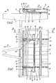
- a chassis frame forming a drawbar 1 at the front end has a front cross member 2 and two side members 3 which are connected by cross members 4. These carry the vehicle floor 5, which here consists of individual wooden boards and is also supported by longitudinal members 6 belonging to the frame. The front boundary edge of the vehicle floor 5 lies some distance behind the front cross member 2, which results in a free space 7 between the two. To form a loading space above the vehicle floor 5 3 side walls (not shown) are attached to the front cross member 2 and the side members.
- the vehicle floor 5 is covered by a scraper chain which consists of two endless link chains 8 which are spaced parallel to one another and which are attached to the crossbars 9 in the transverse direction.
- the upper run of the scraper chain 8, 9 lies on the floor 5, while the lower run runs some distance below the floor 5 and, insofar as it is not with the Last 9 is guided in side rails, sags freely down.
- the scraper chain 8, 9 with its link chains runs over sprockets which are seated on a shaft which is fixed in the chassis frame and can be driven from the side.
- the Krat zerkette 8, 9 roll over freely rotatably mounted chains or deflection wheels 10 and deflected.
- the so or similarly formed and known scraper or transport floor is used to transport agricultural cargo located on the vehicle floor, usually in the direction indicated by arrow a, ie from - based on the direction of travel indicated by arrow b - front to rear end of the vehicle.
- the upper strand of the scraper chain 8, 9, which is under the load of the load, is the drawn strand, while the free lower strand forms the pushed strand.
- an opposite conveying direction as indicated by the arrow c, can be achieved, as is often desired and carried out for better load distribution of the load. In this case, the loaded upper run of this scraper chain 8, 9 becomes the pushed and the free lower run becomes the pulled run.
- the invention provides a tensioning device acting on the front chain rollers or deflection wheels 10, in which the tensioner exerted by a tensioner generator and the front deflecting wheels 10 with a rectilinear offset movement away from the second, fixedly arranged and drivable rear deflection axis, pushing clamping force is transmitted via a feed pressure element with reset inhibition.
- the front deflecting wheels 10 are mounted with their axes in brackets 11, which in turn are guided and supported in a sliding manner with guide shafts 12 in guide pockets 13 formed at the front end of the floor side members 6.
- the feed pressure element is formed in each case by a wedge piece 14 which passes through the guide pocket 13 at the rear end and has a self-locking wedge surface 15 which interacts with the beveled or rounded rear end 12 'of the guide shaft 12.
- a helical spring 16 is provided as the tension force generator, which extends transversely under the vehicle floor and pulls the two wedge pieces 14, which are arranged in the same plane and can be moved in opposite directions with respect to one another, with a corresponding preload.
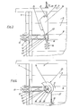
- the wedge pieces 14 at the front end which extends through a slot guide 13 'of the pockets 13, have a straight nose 17 with a hooking eye 18, into which the ends of the helical spring 16 are each suspended (FIG. 3).
- Each wedge piece 14 can by means of a mounting screw 19 which passes through the side support 3 and is supported on the outside thereof by a nut 20 and which is hooked with its inner, appropriately hook-shaped end 19 'into an opening 21 provided at the outer end of the wedge piece 14, insofar as to the side support 3 out of the slot guide in the guide pocket 13 against the tension force of the coil spring 16 are pulled outwards so that there is only the straight nose 17 in the guide pocket 13, so that the front deflection wheel 10 bearing bracket 11 with the guide shaft 12 without tension is posed.
- a hole 22 is provided in the wedge piece, which receives a plug which comes to rest when the mounting screw 19 is loosened on the outer wall of the guide pocket 13 and thus holds the wedge piece 14 in the position shown in FIG. 3 .
- the mounting screw 19 can then be removed and used to also pull the wedge piece 14 on the other side of the vehicle out of the guide pocket 13 into the tension-free end position. This allows the assembly of the scraper chain 8, 9 to be carried out in the usual manner and without hindrance.
- the tensioning device is then activated, i.e.
- the modified exemplary embodiment shown in FIG. 4 differs from the embodiment according to FIGS. 1 to 3 in that a rotatably mounted wedge piece 24 with a spiral self-locking wedge surface 25 is provided as the feed pressure element.
- the rotatable wedge piece 24 is mounted on an axis 26 at the end of the guide pocket 13 and, with its spiral self-locking wedge surface 25, passes through a corresponding slot guide or recess 13 ′′ in the guide pocket 13, so that here, too, the wedge surface 25 interacts with the rear end 12 '.
- a particularly advantageous embodiment is provided if the wedge surfaces 15, 25 on the wedge pieces 14, 24 on the one hand are dimensioned with respect to their length extension on the one hand and the helical spring 16 with regard to their tensioning force on the other hand such that the entire design-related or possible tensioning path for the front deflection wheels 10, how he z. B. results from the free space 7. can be bridged or passed through by the tensioning device. For a usual clamping path of about 70 mm, this can easily be achieved by appropriate length dimensioning of the wedge surfaces 15, 25 and with coil springs designed between 150 and 400 kp clamping force. In this way, the tensioning device can automatically be effective over the entire life of the scraper floor or the like. H. there is no need for manual retensioning during the entire life of the scraper floor.
- a hydraulic piston / cylinder storage unit could also be provided as the clamping force generator instead of the helical spring 16 common to the two wedge pieces. It is also possible to provide two separate clamping force generators for the two wedge pieces instead of a common clamping force generator. Instead of as wedge pieces, the feed pressure genes could e.g.
- the tensioning device according to the invention is not only intended and suitable for scraper floors or similar transport floors on agricultural vehicles, but is also advantageously used for scraper floors or the like on other stationary or movable agricultural machines and devices can.
Landscapes
- Engineering & Computer Science (AREA)
- Mechanical Engineering (AREA)
- Transportation (AREA)
- Agricultural Machines (AREA)
- Handcart (AREA)
- Harvesting Machines For Root Crops (AREA)
- Motor Power Transmission Devices (AREA)
- Chain Conveyers (AREA)
- Fertilizing (AREA)
- Pusher Or Impeller Conveyors (AREA)
- Drives For Endless Conveyors (AREA)
- Loading Or Unloading Of Vehicles (AREA)
- Devices For Conveying Motion By Means Of Endless Flexible Members (AREA)
Claims (7)
Priority Applications (1)
| Application Number | Priority Date | Filing Date | Title |
|---|---|---|---|
| AT83110844T ATE13858T1 (de) | 1982-12-23 | 1983-10-29 | Spannvorrichtung fuer kratzboeden o.ae. transportboeden an landwirtschaftlichen fahzeugen und maschinen. |
Applications Claiming Priority (2)
| Application Number | Priority Date | Filing Date | Title |
|---|---|---|---|
| DE3247625 | 1982-12-23 | ||
| DE3247625A DE3247625C2 (de) | 1982-12-23 | 1982-12-23 | Spannvorrichtung für Kratzböden o.ä. Transportböden an landwirtschaftlichen Fahrzeugen und Maschinen |
Publications (3)
| Publication Number | Publication Date |
|---|---|
| EP0112464A1 EP0112464A1 (fr) | 1984-07-04 |
| EP0112464B1 EP0112464B1 (fr) | 1985-06-19 |
| EP0112464B2 true EP0112464B2 (fr) | 1990-08-29 |
Family
ID=6181496
Family Applications (1)
| Application Number | Title | Priority Date | Filing Date |
|---|---|---|---|
| EP83110844A Expired - Lifetime EP0112464B2 (fr) | 1982-12-23 | 1983-10-29 | Dispositif tendeur pour fonds racleurs ou fonds transporteurs analogues sur véhicules ou engins agricoles |
Country Status (4)
| Country | Link |
|---|---|
| EP (1) | EP0112464B2 (fr) |
| JP (1) | JPS59158715A (fr) |
| AT (1) | ATE13858T1 (fr) |
| DE (2) | DE3247625C2 (fr) |
Families Citing this family (7)
| Publication number | Priority date | Publication date | Assignee | Title |
|---|---|---|---|---|
| DE3512594C1 (de) * | 1985-04-06 | 1986-09-18 | Karl Mengele & Söhne Maschinenfabrik und Eisengießerei GmbH & Co, 8870 Günzburg | Spannvorrichtung für einen Kratzboden von Transportfahrzeugen |
| DE3711765A1 (de) * | 1987-04-07 | 1988-10-27 | Strautmann & Soehne | Zugstrang-spannvorrichtung fuer transportboeden |
| DE4240654A1 (de) * | 1992-12-03 | 1994-06-09 | Kabelmetal Electro Gmbh | Abzugsvorrichtung für langgestrecktes Gut |
| DE20015458U1 (de) * | 2000-09-07 | 2001-02-08 | Max Dörr GmbH, 75050 Gemmingen | Fördervorrichtung |
| CN101962117B (zh) * | 2010-09-03 | 2012-07-25 | 湖南金马矿山设备有限公司 | 一种刮板输送机上用的紧链装置 |
| FR3005234B1 (fr) * | 2013-05-02 | 2015-05-15 | Perard | Systeme de tension d'un fond racleur pour un epandeur et procede de regulation. |
| CN110723049A (zh) * | 2019-10-24 | 2020-01-24 | 山东德曼机械有限公司 | 一种拉索刮板式卸料装置 |
Family Cites Families (1)
| Publication number | Priority date | Publication date | Assignee | Title |
|---|---|---|---|---|
| DE7608133U1 (fr) * | 1900-01-01 | Gebrueder Welger, 3340 Wolfenbuettel |
-
1982
- 1982-12-23 DE DE3247625A patent/DE3247625C2/de not_active Expired
-
1983
- 1983-10-29 AT AT83110844T patent/ATE13858T1/de not_active IP Right Cessation
- 1983-10-29 DE DE8383110844T patent/DE3360304D1/de not_active Expired
- 1983-10-29 EP EP83110844A patent/EP0112464B2/fr not_active Expired - Lifetime
- 1983-12-23 JP JP58242308A patent/JPS59158715A/ja active Pending
Also Published As
| Publication number | Publication date |
|---|---|
| DE3247625C2 (de) | 1985-05-23 |
| DE3247625A1 (de) | 1984-07-05 |
| JPS59158715A (ja) | 1984-09-08 |
| DE3360304D1 (en) | 1985-07-25 |
| ATE13858T1 (de) | 1985-07-15 |
| EP0112464B1 (fr) | 1985-06-19 |
| EP0112464A1 (fr) | 1984-07-04 |
Similar Documents
| Publication | Publication Date | Title |
|---|---|---|
| EP3746380A1 (fr) | Convoyeur à bande, en particulier convoyeur peseur à bande | |
| DE69927067T2 (de) | Antriebseinheit für fördermotor und fördersystem | |
| EP0731040B1 (fr) | Convoyeur à bande articulé avec tension prédéterminée de l'organe de support | |
| DE3421413C2 (fr) | ||
| EP0112464B2 (fr) | Dispositif tendeur pour fonds racleurs ou fonds transporteurs analogues sur véhicules ou engins agricoles | |
| DE3631401C2 (de) | Längsführung für positionierbare Anschlageinrichtungen | |
| EP0161412B1 (fr) | Dispositif de transport pour convoyer des montages supports de pièces | |
| DE602005005556T2 (de) | Vorrichtung zur Einstellung der Spannung eines Treibriemens | |
| DE3934233A1 (de) | Gurtfoerderer | |
| DE3514323C2 (fr) | ||
| EP0473953B1 (fr) | Transporteur de courroie | |
| DE2233832A1 (de) | Einrichtung zum foerdern von lasten | |
| EP0753610B1 (fr) | Carde à chapeaux mobiles | |
| DE2706902A1 (de) | Antrieb fuer eine drehbare trommel | |
| DE69301679T2 (de) | Förderer | |
| WO2018157991A1 (fr) | Dispositif d'amenée et procédé permettant de mettre en place au moins un dispositif d'amenée | |
| DE19731422B4 (de) | Transporteinheit für einen Spannrahmen | |
| DE3313196C1 (de) | Vorrichtung zum Spannen eines bandförmigen Förderorganes | |
| DE3017969C2 (de) | Einrichtung zur Parallelführung der Spanntrommel eines Senkrechtsförderers | |
| DE4206939C1 (fr) | ||
| EP0121920A2 (fr) | Dispositif de transport à bande | |
| DE102021108772B3 (de) | Planenroller zur verschiebbaren lagerung einer plane | |
| DE2646703A1 (de) | Foerderkette und damit ausgestatteter kettenfoerderer | |
| DE2622672C2 (de) | Kettenabweisvorrichtung am Maschinenrahmen eines Kettenkratzförderers | |
| DE3347796C2 (fr) |
Legal Events
| Date | Code | Title | Description |
|---|---|---|---|
| PUAI | Public reference made under article 153(3) epc to a published international application that has entered the european phase |
Free format text: ORIGINAL CODE: 0009012 |
|
| AK | Designated contracting states |
Designated state(s): AT DE FR GB IT NL |
|
| 17P | Request for examination filed |
Effective date: 19840726 |
|
| ITF | It: translation for a ep patent filed | ||
| GRAA | (expected) grant |
Free format text: ORIGINAL CODE: 0009210 |
|
| AK | Designated contracting states |
Designated state(s): AT DE FR GB IT NL |
|
| REF | Corresponds to: |
Ref document number: 13858 Country of ref document: AT Date of ref document: 19850715 Kind code of ref document: T |
|
| REF | Corresponds to: |
Ref document number: 3360304 Country of ref document: DE Date of ref document: 19850725 |
|
| ET | Fr: translation filed | ||
| PLBI | Opposition filed |
Free format text: ORIGINAL CODE: 0009260 |
|
| 26 | Opposition filed |
Opponent name: CLAAS SAULGAU GMBH Effective date: 19851010 |
|
| NLR1 | Nl: opposition has been filed with the epo |
Opponent name: CLAAS SAULGAU GMBH |
|
| PLAB | Opposition data, opponent's data or that of the opponent's representative modified |
Free format text: ORIGINAL CODE: 0009299OPPO |
|
| R26 | Opposition filed (corrected) |
Opponent name: CLAAS SAULGAU GMBH Effective date: 19851010 |
|
| PUAH | Patent maintained in amended form |
Free format text: ORIGINAL CODE: 0009272 |
|
| STAA | Information on the status of an ep patent application or granted ep patent |
Free format text: STATUS: PATENT MAINTAINED AS AMENDED |
|
| 27A | Patent maintained in amended form |
Effective date: 19900829 |
|
| AK | Designated contracting states |
Kind code of ref document: B2 Designated state(s): AT DE FR GB IT NL |
|
| NLR2 | Nl: decision of opposition | ||
| ITF | It: translation for a ep patent filed | ||
| ET3 | Fr: translation filed ** decision concerning opposition | ||
| NLR3 | Nl: receipt of modified translations in the netherlands language after an opposition procedure | ||
| ITTA | It: last paid annual fee | ||
| PGFP | Annual fee paid to national office [announced via postgrant information from national office to epo] |
Ref country code: GB Payment date: 19991014 Year of fee payment: 17 |
|
| PGFP | Annual fee paid to national office [announced via postgrant information from national office to epo] |
Ref country code: AT Payment date: 19991025 Year of fee payment: 17 |
|
| PGFP | Annual fee paid to national office [announced via postgrant information from national office to epo] |
Ref country code: NL Payment date: 19991029 Year of fee payment: 17 Ref country code: FR Payment date: 19991029 Year of fee payment: 17 |
|
| PG25 | Lapsed in a contracting state [announced via postgrant information from national office to epo] |
Ref country code: GB Free format text: LAPSE BECAUSE OF NON-PAYMENT OF DUE FEES Effective date: 20001029 Ref country code: AT Free format text: LAPSE BECAUSE OF NON-PAYMENT OF DUE FEES Effective date: 20001029 |
|
| PG25 | Lapsed in a contracting state [announced via postgrant information from national office to epo] |
Ref country code: NL Free format text: LAPSE BECAUSE OF NON-PAYMENT OF DUE FEES Effective date: 20010501 |
|
| GBPC | Gb: european patent ceased through non-payment of renewal fee |
Effective date: 20001029 |
|
| PG25 | Lapsed in a contracting state [announced via postgrant information from national office to epo] |
Ref country code: FR Free format text: LAPSE BECAUSE OF NON-PAYMENT OF DUE FEES Effective date: 20010629 |
|
| NLV4 | Nl: lapsed or anulled due to non-payment of the annual fee |
Effective date: 20010501 |
|
| REG | Reference to a national code |
Ref country code: FR Ref legal event code: ST |
|
| PGFP | Annual fee paid to national office [announced via postgrant information from national office to epo] |
Ref country code: DE Payment date: 20011119 Year of fee payment: 19 |
|
| PG25 | Lapsed in a contracting state [announced via postgrant information from national office to epo] |
Ref country code: DE Free format text: LAPSE BECAUSE OF NON-PAYMENT OF DUE FEES Effective date: 20030501 |