EP0293398B1 - Verfahren und einrichtung zum steuern von sicherheitsventilen - Google Patents
Verfahren und einrichtung zum steuern von sicherheitsventilen Download PDFInfo
- Publication number
- EP0293398B1 EP0293398B1 EP19870906294 EP87906294A EP0293398B1 EP 0293398 B1 EP0293398 B1 EP 0293398B1 EP 19870906294 EP19870906294 EP 19870906294 EP 87906294 A EP87906294 A EP 87906294A EP 0293398 B1 EP0293398 B1 EP 0293398B1
- Authority
- EP
- European Patent Office
- Prior art keywords
- pressure
- solenoid valves
- opening
- valve
- valves
- Prior art date
- Legal status (The legal status is an assumption and is not a legal conclusion. Google has not performed a legal analysis and makes no representation as to the accuracy of the status listed.)
- Expired - Lifetime
Links
Images

Classifications
-
- F—MECHANICAL ENGINEERING; LIGHTING; HEATING; WEAPONS; BLASTING
- F16—ENGINEERING ELEMENTS AND UNITS; GENERAL MEASURES FOR PRODUCING AND MAINTAINING EFFECTIVE FUNCTIONING OF MACHINES OR INSTALLATIONS; THERMAL INSULATION IN GENERAL
- F16K—VALVES; TAPS; COCKS; ACTUATING-FLOATS; DEVICES FOR VENTING OR AERATING
- F16K31/00—Actuating devices; Operating means; Releasing devices
- F16K31/12—Actuating devices; Operating means; Releasing devices actuated by fluid
- F16K31/122—Actuating devices; Operating means; Releasing devices actuated by fluid the fluid acting on a piston
- F16K31/124—Actuating devices; Operating means; Releasing devices actuated by fluid the fluid acting on a piston servo actuated
- F16K31/1245—Actuating devices; Operating means; Releasing devices actuated by fluid the fluid acting on a piston servo actuated with more than one valve
-
- H—ELECTRICITY
- H10—SEMICONDUCTOR DEVICES; ELECTRIC SOLID-STATE DEVICES NOT OTHERWISE PROVIDED FOR
- H10W—GENERIC PACKAGES, INTERCONNECTIONS, CONNECTORS OR OTHER CONSTRUCTIONAL DETAILS OF DEVICES COVERED BY CLASS H10
- H10W76/00—Containers; Fillings or auxiliary members therefor; Seals
- H10W76/10—Containers or parts thereof
- H10W76/12—Containers or parts thereof characterised by their shape
- H10W76/13—Containers comprising a conductive base serving as an interconnection
- H10W76/134—Containers comprising a conductive base serving as an interconnection having other interconnections parallel to the conductive base
-
- F—MECHANICAL ENGINEERING; LIGHTING; HEATING; WEAPONS; BLASTING
- F15—FLUID-PRESSURE ACTUATORS; HYDRAULICS OR PNEUMATICS IN GENERAL
- F15B—SYSTEMS ACTING BY MEANS OF FLUIDS IN GENERAL; FLUID-PRESSURE ACTUATORS, e.g. SERVOMOTORS; DETAILS OF FLUID-PRESSURE SYSTEMS, NOT OTHERWISE PROVIDED FOR
- F15B19/00—Testing; Calibrating; Fault detection or monitoring; Simulation or modelling of fluid-pressure systems or apparatus not otherwise provided for
- F15B19/002—Calibrating
-
- F—MECHANICAL ENGINEERING; LIGHTING; HEATING; WEAPONS; BLASTING
- F16—ENGINEERING ELEMENTS AND UNITS; GENERAL MEASURES FOR PRODUCING AND MAINTAINING EFFECTIVE FUNCTIONING OF MACHINES OR INSTALLATIONS; THERMAL INSULATION IN GENERAL
- F16K—VALVES; TAPS; COCKS; ACTUATING-FLOATS; DEVICES FOR VENTING OR AERATING
- F16K17/00—Safety valves; Equalising valves, e.g. pressure relief valves
- F16K17/02—Safety valves; Equalising valves, e.g. pressure relief valves opening on surplus pressure on one side; closing on insufficient pressure on one side
-
- G—PHYSICS
- G05—CONTROLLING; REGULATING
- G05D—SYSTEMS FOR CONTROLLING OR REGULATING NON-ELECTRIC VARIABLES
- G05D16/00—Control of fluid pressure
- G05D16/024—Controlling the inlet pressure, e.g. back-pressure regulator
-
- G—PHYSICS
- G05—CONTROLLING; REGULATING
- G05D—SYSTEMS FOR CONTROLLING OR REGULATING NON-ELECTRIC VARIABLES
- G05D16/00—Control of fluid pressure
- G05D16/20—Control of fluid pressure characterised by the use of electric means
- G05D16/2093—Control of fluid pressure characterised by the use of electric means with combination of electric and non-electric auxiliary power
- G05D16/2097—Control of fluid pressure characterised by the use of electric means with combination of electric and non-electric auxiliary power using pistons within the main valve
-
- H—ELECTRICITY
- H10—SEMICONDUCTOR DEVICES; ELECTRIC SOLID-STATE DEVICES NOT OTHERWISE PROVIDED FOR
- H10W—GENERIC PACKAGES, INTERCONNECTIONS, CONNECTORS OR OTHER CONSTRUCTIONAL DETAILS OF DEVICES COVERED BY CLASS H10
- H10W70/00—Package substrates; Interposers; Redistribution layers [RDL]
- H10W70/40—Leadframes
- H10W70/481—Leadframes for devices being provided for in groups H10D8/00 - H10D48/00
-
- H—ELECTRICITY
- H10—SEMICONDUCTOR DEVICES; ELECTRIC SOLID-STATE DEVICES NOT OTHERWISE PROVIDED FOR
- H10W—GENERIC PACKAGES, INTERCONNECTIONS, CONNECTORS OR OTHER CONSTRUCTIONAL DETAILS OF DEVICES COVERED BY CLASS H10
- H10W70/00—Package substrates; Interposers; Redistribution layers [RDL]
- H10W70/60—Insulating or insulated package substrates; Interposers; Redistribution layers
- H10W70/67—Insulating or insulated package substrates; Interposers; Redistribution layers characterised by their insulating layers or insulating parts
- H10W70/68—Shapes or dispositions thereof
- H10W70/682—Shapes or dispositions thereof comprising holes having chips therein
-
- H—ELECTRICITY
- H10—SEMICONDUCTOR DEVICES; ELECTRIC SOLID-STATE DEVICES NOT OTHERWISE PROVIDED FOR
- H10W—GENERIC PACKAGES, INTERCONNECTIONS, CONNECTORS OR OTHER CONSTRUCTIONAL DETAILS OF DEVICES COVERED BY CLASS H10
- H10W72/00—Interconnections or connectors in packages
- H10W72/071—Connecting or disconnecting
- H10W72/073—Connecting or disconnecting of die-attach connectors
- H10W72/07331—Connecting techniques
- H10W72/07336—Soldering or alloying
-
- H—ELECTRICITY
- H10—SEMICONDUCTOR DEVICES; ELECTRIC SOLID-STATE DEVICES NOT OTHERWISE PROVIDED FOR
- H10W—GENERIC PACKAGES, INTERCONNECTIONS, CONNECTORS OR OTHER CONSTRUCTIONAL DETAILS OF DEVICES COVERED BY CLASS H10
- H10W72/00—Interconnections or connectors in packages
- H10W72/071—Connecting or disconnecting
- H10W72/075—Connecting or disconnecting of bond wires
- H10W72/07521—Aligning
-
- H—ELECTRICITY
- H10—SEMICONDUCTOR DEVICES; ELECTRIC SOLID-STATE DEVICES NOT OTHERWISE PROVIDED FOR
- H10W—GENERIC PACKAGES, INTERCONNECTIONS, CONNECTORS OR OTHER CONSTRUCTIONAL DETAILS OF DEVICES COVERED BY CLASS H10
- H10W72/00—Interconnections or connectors in packages
- H10W72/071—Connecting or disconnecting
- H10W72/076—Connecting or disconnecting of strap connectors
- H10W72/07631—Techniques
- H10W72/07636—Soldering or alloying
-
- H—ELECTRICITY
- H10—SEMICONDUCTOR DEVICES; ELECTRIC SOLID-STATE DEVICES NOT OTHERWISE PROVIDED FOR
- H10W—GENERIC PACKAGES, INTERCONNECTIONS, CONNECTORS OR OTHER CONSTRUCTIONAL DETAILS OF DEVICES COVERED BY CLASS H10
- H10W72/00—Interconnections or connectors in packages
- H10W72/071—Connecting or disconnecting
- H10W72/076—Connecting or disconnecting of strap connectors
- H10W72/07651—Connecting or disconnecting of strap connectors characterised by changes in properties of the strap connectors during connecting
- H10W72/07653—Connecting or disconnecting of strap connectors characterised by changes in properties of the strap connectors during connecting changes in shapes
-
- H—ELECTRICITY
- H10—SEMICONDUCTOR DEVICES; ELECTRIC SOLID-STATE DEVICES NOT OTHERWISE PROVIDED FOR
- H10W—GENERIC PACKAGES, INTERCONNECTIONS, CONNECTORS OR OTHER CONSTRUCTIONAL DETAILS OF DEVICES COVERED BY CLASS H10
- H10W72/00—Interconnections or connectors in packages
- H10W72/50—Bond wires
-
- H—ELECTRICITY
- H10—SEMICONDUCTOR DEVICES; ELECTRIC SOLID-STATE DEVICES NOT OTHERWISE PROVIDED FOR
- H10W—GENERIC PACKAGES, INTERCONNECTIONS, CONNECTORS OR OTHER CONSTRUCTIONAL DETAILS OF DEVICES COVERED BY CLASS H10
- H10W72/00—Interconnections or connectors in packages
- H10W72/50—Bond wires
- H10W72/531—Shapes of wire connectors
- H10W72/537—Multiple bond wires having different shapes
-
- H—ELECTRICITY
- H10—SEMICONDUCTOR DEVICES; ELECTRIC SOLID-STATE DEVICES NOT OTHERWISE PROVIDED FOR
- H10W—GENERIC PACKAGES, INTERCONNECTIONS, CONNECTORS OR OTHER CONSTRUCTIONAL DETAILS OF DEVICES COVERED BY CLASS H10
- H10W72/00—Interconnections or connectors in packages
- H10W72/60—Strap connectors, e.g. thick copper clips for grounding of power devices
- H10W72/651—Materials of strap connectors
- H10W72/652—Materials of strap connectors comprising metals or metalloids, e.g. silver
-
- H—ELECTRICITY
- H10—SEMICONDUCTOR DEVICES; ELECTRIC SOLID-STATE DEVICES NOT OTHERWISE PROVIDED FOR
- H10W—GENERIC PACKAGES, INTERCONNECTIONS, CONNECTORS OR OTHER CONSTRUCTIONAL DETAILS OF DEVICES COVERED BY CLASS H10
- H10W72/00—Interconnections or connectors in packages
- H10W72/851—Dispositions of multiple connectors or interconnections
- H10W72/853—On the same surface
- H10W72/871—Bond wires and strap connectors
-
- H—ELECTRICITY
- H10—SEMICONDUCTOR DEVICES; ELECTRIC SOLID-STATE DEVICES NOT OTHERWISE PROVIDED FOR
- H10W—GENERIC PACKAGES, INTERCONNECTIONS, CONNECTORS OR OTHER CONSTRUCTIONAL DETAILS OF DEVICES COVERED BY CLASS H10
- H10W72/00—Interconnections or connectors in packages
- H10W72/851—Dispositions of multiple connectors or interconnections
- H10W72/874—On different surfaces
- H10W72/884—Die-attach connectors and bond wires
-
- H—ELECTRICITY
- H10—SEMICONDUCTOR DEVICES; ELECTRIC SOLID-STATE DEVICES NOT OTHERWISE PROVIDED FOR
- H10W—GENERIC PACKAGES, INTERCONNECTIONS, CONNECTORS OR OTHER CONSTRUCTIONAL DETAILS OF DEVICES COVERED BY CLASS H10
- H10W90/00—Package configurations
- H10W90/701—Package configurations characterised by the relative positions of pads or connectors relative to package parts
- H10W90/751—Package configurations characterised by the relative positions of pads or connectors relative to package parts of bond wires
- H10W90/756—Package configurations characterised by the relative positions of pads or connectors relative to package parts of bond wires between a chip and a stacked lead frame, conducting package substrate or heat sink
-
- H—ELECTRICITY
- H10—SEMICONDUCTOR DEVICES; ELECTRIC SOLID-STATE DEVICES NOT OTHERWISE PROVIDED FOR
- H10W—GENERIC PACKAGES, INTERCONNECTIONS, CONNECTORS OR OTHER CONSTRUCTIONAL DETAILS OF DEVICES COVERED BY CLASS H10
- H10W90/00—Package configurations
- H10W90/701—Package configurations characterised by the relative positions of pads or connectors relative to package parts
- H10W90/761—Package configurations characterised by the relative positions of pads or connectors relative to package parts of strap connectors
- H10W90/766—Package configurations characterised by the relative positions of pads or connectors relative to package parts of strap connectors between a chip and a stacked lead frame, conducting package substrate or heat sink
-
- H—ELECTRICITY
- H10—SEMICONDUCTOR DEVICES; ELECTRIC SOLID-STATE DEVICES NOT OTHERWISE PROVIDED FOR
- H10W—GENERIC PACKAGES, INTERCONNECTIONS, CONNECTORS OR OTHER CONSTRUCTIONAL DETAILS OF DEVICES COVERED BY CLASS H10
- H10W99/00—Subject matter not provided for in other groups of this subclass
-
- F—MECHANICAL ENGINEERING; LIGHTING; HEATING; WEAPONS; BLASTING
- F15—FLUID-PRESSURE ACTUATORS; HYDRAULICS OR PNEUMATICS IN GENERAL
- F15B—SYSTEMS ACTING BY MEANS OF FLUIDS IN GENERAL; FLUID-PRESSURE ACTUATORS, e.g. SERVOMOTORS; DETAILS OF FLUID-PRESSURE SYSTEMS, NOT OTHERWISE PROVIDED FOR
- F15B2211/00—Circuits for servomotor systems
- F15B2211/50—Pressure control
- F15B2211/505—Pressure control characterised by the type of pressure control means
- F15B2211/50509—Pressure control characterised by the type of pressure control means the pressure control means controlling a pressure upstream of the pressure control means
-
- F—MECHANICAL ENGINEERING; LIGHTING; HEATING; WEAPONS; BLASTING
- F15—FLUID-PRESSURE ACTUATORS; HYDRAULICS OR PNEUMATICS IN GENERAL
- F15B—SYSTEMS ACTING BY MEANS OF FLUIDS IN GENERAL; FLUID-PRESSURE ACTUATORS, e.g. SERVOMOTORS; DETAILS OF FLUID-PRESSURE SYSTEMS, NOT OTHERWISE PROVIDED FOR
- F15B2211/00—Circuits for servomotor systems
- F15B2211/50—Pressure control
- F15B2211/505—Pressure control characterised by the type of pressure control means
- F15B2211/50554—Pressure control characterised by the type of pressure control means the pressure control means controlling a pressure downstream of the pressure control means, e.g. pressure reducing valve
-
- F—MECHANICAL ENGINEERING; LIGHTING; HEATING; WEAPONS; BLASTING
- F15—FLUID-PRESSURE ACTUATORS; HYDRAULICS OR PNEUMATICS IN GENERAL
- F15B—SYSTEMS ACTING BY MEANS OF FLUIDS IN GENERAL; FLUID-PRESSURE ACTUATORS, e.g. SERVOMOTORS; DETAILS OF FLUID-PRESSURE SYSTEMS, NOT OTHERWISE PROVIDED FOR
- F15B2211/00—Circuits for servomotor systems
- F15B2211/50—Pressure control
- F15B2211/515—Pressure control characterised by the connections of the pressure control means in the circuit
- F15B2211/5158—Pressure control characterised by the connections of the pressure control means in the circuit being connected to a pressure source and an output member
-
- F—MECHANICAL ENGINEERING; LIGHTING; HEATING; WEAPONS; BLASTING
- F15—FLUID-PRESSURE ACTUATORS; HYDRAULICS OR PNEUMATICS IN GENERAL
- F15B—SYSTEMS ACTING BY MEANS OF FLUIDS IN GENERAL; FLUID-PRESSURE ACTUATORS, e.g. SERVOMOTORS; DETAILS OF FLUID-PRESSURE SYSTEMS, NOT OTHERWISE PROVIDED FOR
- F15B2211/00—Circuits for servomotor systems
- F15B2211/50—Pressure control
- F15B2211/515—Pressure control characterised by the connections of the pressure control means in the circuit
- F15B2211/5159—Pressure control characterised by the connections of the pressure control means in the circuit being connected to an output member and a return line
-
- F—MECHANICAL ENGINEERING; LIGHTING; HEATING; WEAPONS; BLASTING
- F15—FLUID-PRESSURE ACTUATORS; HYDRAULICS OR PNEUMATICS IN GENERAL
- F15B—SYSTEMS ACTING BY MEANS OF FLUIDS IN GENERAL; FLUID-PRESSURE ACTUATORS, e.g. SERVOMOTORS; DETAILS OF FLUID-PRESSURE SYSTEMS, NOT OTHERWISE PROVIDED FOR
- F15B2211/00—Circuits for servomotor systems
- F15B2211/50—Pressure control
- F15B2211/52—Pressure control characterised by the type of actuation
- F15B2211/526—Pressure control characterised by the type of actuation electrically or electronically
- F15B2211/527—Pressure control characterised by the type of actuation electrically or electronically with signal modulation, e.g. pulse width modulation [PWM]
-
- Y—GENERAL TAGGING OF NEW TECHNOLOGICAL DEVELOPMENTS; GENERAL TAGGING OF CROSS-SECTIONAL TECHNOLOGIES SPANNING OVER SEVERAL SECTIONS OF THE IPC; TECHNICAL SUBJECTS COVERED BY FORMER USPC CROSS-REFERENCE ART COLLECTIONS [XRACs] AND DIGESTS
- Y10—TECHNICAL SUBJECTS COVERED BY FORMER USPC
- Y10T—TECHNICAL SUBJECTS COVERED BY FORMER US CLASSIFICATION
- Y10T137/00—Fluid handling
- Y10T137/0318—Processes
- Y10T137/0396—Involving pressure control
-
- Y—GENERAL TAGGING OF NEW TECHNOLOGICAL DEVELOPMENTS; GENERAL TAGGING OF CROSS-SECTIONAL TECHNOLOGIES SPANNING OVER SEVERAL SECTIONS OF THE IPC; TECHNICAL SUBJECTS COVERED BY FORMER USPC CROSS-REFERENCE ART COLLECTIONS [XRACs] AND DIGESTS
- Y10—TECHNICAL SUBJECTS COVERED BY FORMER USPC
- Y10T—TECHNICAL SUBJECTS COVERED BY FORMER US CLASSIFICATION
- Y10T137/00—Fluid handling
- Y10T137/7722—Line condition change responsive valves
- Y10T137/7758—Pilot or servo controlled
- Y10T137/7761—Electrically actuated valve
-
- Y—GENERAL TAGGING OF NEW TECHNOLOGICAL DEVELOPMENTS; GENERAL TAGGING OF CROSS-SECTIONAL TECHNOLOGIES SPANNING OVER SEVERAL SECTIONS OF THE IPC; TECHNICAL SUBJECTS COVERED BY FORMER USPC CROSS-REFERENCE ART COLLECTIONS [XRACs] AND DIGESTS
- Y10—TECHNICAL SUBJECTS COVERED BY FORMER USPC
- Y10T—TECHNICAL SUBJECTS COVERED BY FORMER US CLASSIFICATION
- Y10T137/00—Fluid handling
- Y10T137/8593—Systems
- Y10T137/86389—Programmer or timer
Definitions
- the invention relates to a method and a device for controlling safety valves, in which or in which the closure body is pressed against the pressure of the medium to be secured by a control cylinder connected to a hydraulic control circuit on the valve seat, wherein when the response pressure is reached to achieve the Valve opening stroke open one or more discharge solenoid valves controlled by pressure transducers and drain the hydraulic fluid from the actuating cylinder, which close again when the response pressure is undershot, hydraulic fluid being supplied to the actuating cylinder for the valve closing process.
- the actuating cylinder is constantly in open connection with the pressure line of the hydraulic control circuit via a throttle, and when the response pressure is reached, pressure switches respond which open the drain solenoid valves and hold them open until the medium pressure falls below the switching threshold of the pressure switches Has. Due to the constant load pressure, hydraulic fluid flows into the actuating cylinder after the solenoid valves close and closes the safety valve again.
- the object of the invention is to find a method and a device for controlling safety valves, in which or in which the safety valve rapidly discharges large amounts of medium at high pressure increase speed in the event of danger, however a slow pressure increase only opens as long and as long as the small amount of medium required to compensate for the small pressure increase is required for discharge, and the opening and closing behavior of the safety valve can also be adapted to the respective system conditions at any time.
- the valve behavior can be easily adjusted to the system conditions and can be adapted to the changed system conditions at any time by changing the characteristic curves without taking the valve device out of operation .
- the computer calculates the quantity of hydraulic fluid to be discharged from the actuating cylinder or the quantity of hydraulic fluid to be fed to the actuating cylinder, and the electrical opening pulses of the solenoid valves are determined for each cycle, with the smallest amounts of hydraulic fluid being discharged or supplied and thus performing even the smallest lifting steps of the valve closure member
- Fast-response drain solenoid valves and inflow solenoid valves are used, the shortest response times of which are, for example, 2 ms.
- the query and computer cycle time can also be selected to be very short, so that the system to be protected can be fine-tuned at any time to the changing pressure conditions.
- the opening pulses defined for each cycle are delivered via an amplifier to the drain or inflow solenoid valves, which then remain open for the duration of the calculated opening time and thereby the Control the opening or closing process of the safety valve in accordance with the entered characteristic curves at low pressure change speeds in small stroke steps and at high pressure change speeds in large stroke steps. At very high pressure change speeds, on the other hand, the opening or closing process takes place in a single stroke step up to the end of stroke position.
- This control method can also be applied to safety shut-off valves, in which the valve closure body is in the open position at a pressure below the response pressure and is moved into the closed position by gradually discharging the hydraulic fluid from the actuating cylinder when the response pressure is exceeded.
- the entered characteristic curve or the characteristic curves are in a pressure range provided between a lower response pressure Pu and an upper response pressure P0, and the computer performs the calculation of the opening pulses for the fast-response solenoid valves only in this pressure range in time. Since the safety valve reacts to the smallest pressure changes through the proposed control and the valve closure body can also remain in any intermediate position if the discharged medium quantity of the pressure system to be secured is large enough to keep the pressure constant, the pressure range between P0 and Pu can be kept small . Experience has shown that the pressure difference between P0 and Pu can be about 5% of the upper response pressure P0 at higher response pressures.
- the step control can remain out of operation. If the upper response pressure P0 is exceeded, the computer gives a permanent opening signal to the amplifier acting on the drain solenoid valves instead of the opening pulses, and if the pressure drops below the lower response pressure Pu, a permanent closing signal is emitted to the drain solenoid valves.
- a finer response of the control at low pressure rise speeds and a faster response at higher pressure rise speeds is achieved according to claim 5 in that fast-responding solenoid valves are provided with a variable opening cross section.
- the quantity of hydraulic fluid to be discharged or supplied can be determined not only by the opening time but also by the different opening cross sections of the solenoid valves, as a result of which the span between the smallest and the largest quantity of hydraulic fluid to be discharged or supplied is significantly increased.
- the possible changes in the opening cross sections of the solenoid valves used are stored electronically and the opening cross sections of the solenoid valves used are taken into account when calculating the opening pulses.
- pilot-operated solenoid valves are provided as fast-acting solenoid valves according to the feature of claim 6, the free flow cross-section is automatically controlled by the duration of the opening pulses. With short opening pulses only the pilot cone with a small cross section opens, while with long opening pulses the large main cone cross section is released.
- the loading pressure in the actuating cylinder and also the pressure in the memory of the hydraulic control circuit change.
- the amount of hydraulic fluid flowing through the inflow solenoid valves per unit of time depends not only on the flow cross section but also on the difference between the storage pressure and the loading pressure. Accordingly, according to the feature of claim 11, the pressure difference between the pressure in the memory of the hydraulic control circuit and the loading pressure in the actuating cylinder is measured in time and taken into account in the calculation of the opening pulses of the inflow solenoid valve or valves as a correction variable.
- the heating of the hydraulic fluid can be done in a simple manner
- the hydraulic pump of the hydraulic control circuit is switched on or remains on until the temperature drops below the lower temperature limit until the hydraulic fluid has been sufficiently heated by the power loss of the hydraulic system converted into thermal energy.
- the electronic device provided for the control of the safety valve also makes it possible to increase the functional safety of the safety valve by monitoring the most important components and promptly reporting faults.
- the control of the lifting steps takes place via a drain solenoid valve in the pressure range between the lower response pressure Pu and the upper response pressure P0, while the other two drain solenoid valves controlled directly by the pressure switches are activated according to claim 20 only when the upper response pressure P0 is exceeded. This ensures the safe opening of the safety valve even if the electronic control fails.
- All hydraulic components are expediently installed in a small space in a pot-like housing, which at the same time forms the reservoir for the hydraulic fluid.
- This arrangement gives the shortest line connections between the individual hydraulic components, and the components are protected against mechanical external influences by the pot.
- An explosion-proof design results in a simple manner in that, according to claim 22, all electrical parts of the hydraulic control circuit, which are installed in the reservoir, are washed by an electrically non-conductive hydraulic oil as reservoir oil. This also protects the parts in the oil against overheating.
- the reservoir containing the hydraulic parts can be placed on the actuating cylinder in a simple manner due to the compact design, whereby the shortest connection paths from the hydraulic control circuit to the actuating cylinder are created and the system is particularly compact.
- the cooling fins according to claim 24 the heat-emitting surface of the hydraulic housing is significantly increased, so that a high power loss can be quickly released to the environment. If two memories connected in parallel are provided in the hydraulic control circuit in accordance with the feature of claim 25, a faultless control function of the solenoid valves is still guaranteed if one memory fails, and the two memories can be accommodated in a smaller space in the central housing.
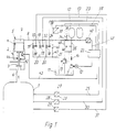
- the system 1 to be protected is provided with a safety valve 2, the valve closure member 3 of which is pressed by the piston 4 of a hydraulic actuating cylinder 5 onto the valve seat 6 and thereby holds the safety valve 2 in the closed position.
- the load chamber 7 of the actuating cylinder 5 is connected via a hydraulic line 8 to a hydraulic control circuit, the basic structure of which consists of a hydraulic pump 9 with a motor 10, an oil reservoir 11 and two accumulators 12 and 13 connected in parallel.
- a check valve 14 and a pressure relief valve 15 are also provided in the hydraulic control circuit.
- the hydraulic fluid is removed from the load chamber 7 of the actuating cylinder 5 Via three drain solenoid valves 16, 17 and 18 lying parallel to one another, which are connected on the input side via the branch lines 19 to the hydraulic line 8 and on the output side via the branch lines 20 to the drain line 21 leading to the oil reservoir 11.
- the drain solenoid valve 16 is controlled by an electronic assembly 22, which transmits opening pulses to the electrical switching part 24 or the solenoid of the drain solenoid valve 16 via a control line 23.
- the electronics module 22 is connected on the input side via the measuring line 25 to the electrical signal output 26 of a pressure sensor 27 connected to the system 1 to be protected.
- two further pressure transducers 28 and 29 are connected in parallel to the pressure transducer 27 to the system 1 to be protected, which are designed as pressure switches and are directly connected to the solenoid coils 32 and 33 of the other two drain solenoid valves 17 and 18 via the two control lines 30 and 31 .
- the closing process of the safety valve 2 is controlled via the inflow solenoid valve 34, which is connected on the input side to the pressure line 35 of the hydraulic control circuit and on the output side to the hydraulic line 8 leading to the load chamber 7 is.
- the electrical switching part 36 or the solenoid of the inflow solenoid valve 34 is switched via the control line 37 from the electronic assembly 22.
- the electronic assembly 22 all the electronic assemblies required for controlling the opening or closing process of the safety valve 2, such as computers, memories, amplifiers and the other electronic modules, are combined, the desired characteristic curve or the characteristic curves for the medium pressure and the rate of pressure change determined in the memory the stroke of the valve plug body must be entered before starting up the system.
- the electronic assembly 22 calculates the pressure change rate per cycle and, in comparison with the stored characteristic curve, the size of the stroke step of the valve closure member to be carried out for each cycle. To carry out this lifting step, the amount of oil to be discharged from the loading chamber 7 is determined in the electronic assembly 22 and the opening pulse to be transmitted to the drain solenoid valve 16 is calculated therefrom.
- the safety valve 2 is thereby opened step by step in time.
- the safety valve 2 is also closed via the electronic assembly 22, but now by gradually controlling the inflow solenoid valve 36.
- a pressure transducer 38 is also connected to hydraulic line 8, the electrical output of which is connected to electronics unit 22 via measuring line 39.
- Another pressure and temperature sensor 40 is connected to the pressure line 35 of the hydraulic control circuit, the electrical output of which is connected to the electronic assembly via the measuring line 41. Via this pressure and temperature sensor 40, the differential pressure which is present at the inflow solenoid valve 34 and the temperature of the hydraulic oil can be taken into account as a correction variable when calculating the opening pulses.
- a stroke sensor 42 is also provided on the piston 4 of the actuating cylinder 5, the electrical output of which is connected to the electronic assembly 22 via the measuring line 43.
- the valve opening spring 44 has been provided in the safety valve 2 so that the movable valve parts are moved into the valve open position when the system 1 to be protected is depressurized.
- the control of the valve stroke takes place via the drain solenoid valve 16 and the inflow solenoid valve 34. Only when the medium pressure rises above the upper response pressure P0, also open the two drain solenoid valves 17 and 18, which are controlled directly by the pressure switches 28 and 29.
- the installation connections 45 and 46 in the parallel lines 47 and 48 have been provided so that an additional drain solenoid valve or an additional inflow solenoid valve can be installed.
- the diagram shown in FIG. 2 shows the system pressure P as a function of time t.
- the curve 49 shows the course of the system pressure in a certain time period.
- the gradual control of the valve opening and valve closing stroke takes place in the pressure range between the lower response pressure Pu and the upper response pressure P0, the characteristic curve 50 showing the opening pulses 51 of the drain solenoid valve and the characteristic curve 52 showing the opening pulses 53 of the inflow solenoid valve.
- the distances between the points 54 of the curve 49 characterize the individual cycles in which the individual lifting steps take place.
- the valve closure body 3 is cyclically raised in steps 51, whereby medium is increasingly discharged, so that the pressure rise rate in the system, which is due to the inclination of the Curve 49 can be seen, decreases steadily and finally changes into a horizontal course with the pressure change rate zero. From this moment on, no opening pulses are transmitted to the drain solenoid valve, and the valve closing body 3 remains in its last stroke position reached. If the disturbance which triggers the pressure increase in the system is removed, the system pressure drops, as the right half of the pressure curve 49 shows.
- the valve closure member is gradually closed by the opening pulses 53 acting on the inflow solenoid valve until the lower response pressure Pu is undershot.
- the inflow solenoid valve 34 remains in the permanently open position so that the hydraulic pressure is constantly present in the loading chamber 7 of the actuating cylinder 5.
- FIG. 3 shows an example of the characteristic curves for the stroke H to be entered in the electronic memory as a function of the system pressure P and at the same time as a function of the pressure change rate of the system pressure.
- the pressure range in which the control of the safety valve is carried out step by step lies between the lower response pressure Pu and the upper response pressure P0.
- the characteristic curves 55, 56, 57 and 58 show the desired dependence of the desired stroke on the rate of pressure rise and on the system pressure P.
- the horizontal stroke characteristic curve 59 indicates the stroke end position of the safety valve.
- the characteristic curve 55 applies to a low rate of pressure increase of e.g. B.
- the characteristic curve 58 represents the upper limit of the pressure rise rate of, for example, 5% / s or more of the response pressure.
- the characteristic curves 56 and 57 identify integer intermediate values in the pressure rise speeds, the remaining gaps between these characteristic curves being able to be subdivided as desired by further intermediate characteristic curves. If, for example, the system pressure has risen to the pressure P 1 at the start of any cycle, and the pressure rise speed is about 1% / s according to the characteristic curve 55, this results in a desired stroke H 1 to be carried out from the diagram.
- the system pressure rises to the value P2, and the pressure rise speed increases to an approximately higher value lying between the two characteristic curves 55 and 56, so that a desired stroke H2 results, so that the stroke step to be carried out for this cycle Difference between the target stroke H2 and the target stroke H1 results.
- the middle hatched area 60 applies to very small pressure change speeds, for example in the range of plus / minus 0.1% / s of the response pressure. In this area, only the system pressure P is used to determine the setpoint stroke. If the system pressure has risen, for example, to a value P3, and the pressure change rate is in the shaded area 60, the desired stroke H3 results, so that a stroke step resulting from the difference between H3 and H2 must be carried out.
- the characteristic curves 61, 62, 63 and 64 lying on the hatched field 60 apply to negative pressure change speeds, ie for falling system pressure.
- the characteristic curve 61 applies e.g. B. for a pressure drop rate of 1% / s of the response pressure, while the curves 62 and 63 indicate larger pressure drop speeds.
- the characteristic curve 64 applies to pressure drop speeds of, for example, 10% / s or more. If the system pressure falls from P3 to P4 and the pressure drop speed is on the characteristic curve 61, the desired stroke H4 results.
- the stroke step to be carried out for this cycle is calculated from the difference H4 minus H3.
- the result is negative, from which it can be seen that a lifting step has to take place in the closing direction.
Landscapes
- Engineering & Computer Science (AREA)
- Physics & Mathematics (AREA)
- General Engineering & Computer Science (AREA)
- Fluid Mechanics (AREA)
- Mechanical Engineering (AREA)
- General Physics & Mathematics (AREA)
- Automation & Control Theory (AREA)
- Fluid-Pressure Circuits (AREA)
- Fluid-Driven Valves (AREA)
- Safety Valves (AREA)
- Magnetically Actuated Valves (AREA)
- Control Of Fluid Pressure (AREA)
Priority Applications (1)
| Application Number | Priority Date | Filing Date | Title |
|---|---|---|---|
| AT87906294T ATE92202T1 (de) | 1986-10-04 | 1987-10-01 | Verfahren und einrichtung zum steuern von sicherheitsventilen. |
Applications Claiming Priority (2)
| Application Number | Priority Date | Filing Date | Title |
|---|---|---|---|
| DE3633851 | 1986-10-04 | ||
| DE19863633851 DE3633851A1 (de) | 1986-10-04 | 1986-10-04 | Verfahren und einrichtung zum steuern von sicherheitsventilen |
Publications (2)
| Publication Number | Publication Date |
|---|---|
| EP0293398A1 EP0293398A1 (de) | 1988-12-07 |
| EP0293398B1 true EP0293398B1 (de) | 1993-07-28 |
Family
ID=6311060
Family Applications (1)
| Application Number | Title | Priority Date | Filing Date |
|---|---|---|---|
| EP19870906294 Expired - Lifetime EP0293398B1 (de) | 1986-10-04 | 1987-10-01 | Verfahren und einrichtung zum steuern von sicherheitsventilen |
Country Status (7)
| Country | Link |
|---|---|
| US (1) | US4911192A (https=) |
| EP (1) | EP0293398B1 (https=) |
| JP (1) | JPH01501242A (https=) |
| KR (1) | KR880701907A (https=) |
| DE (1) | DE3633851A1 (https=) |
| FI (1) | FI882560A7 (https=) |
| WO (1) | WO1988002510A1 (https=) |
Cited By (1)
| Publication number | Priority date | Publication date | Assignee | Title |
|---|---|---|---|---|
| DE102015119108A1 (de) * | 2015-11-06 | 2017-05-11 | Pleiger Maschinenbau Gmbh & Co. Kg | Verfahren und Vorrichtung zum Ansteuern einer hydraulisch betätigten Antriebseinheit einer Armatur |
Families Citing this family (21)
| Publication number | Priority date | Publication date | Assignee | Title |
|---|---|---|---|---|
| DE3927110A1 (de) * | 1989-08-17 | 1991-02-21 | Bosch Gmbh Robert | Magnetventil mit erregerstrom-steuervorrichtung |
| DE4008749C2 (de) * | 1990-03-19 | 1999-02-18 | Mannesmann Vdo Ag | Drucksteueranordnung |
| US5198241A (en) * | 1991-01-29 | 1993-03-30 | Spex Industries, Inc. | Apparatus for preparation of samples for spectrographic analysis |
| DE4404224A1 (de) * | 1994-02-10 | 1995-08-17 | Danfoss As | Hydraulische Funktionseinheit |
| US5522428A (en) * | 1994-08-29 | 1996-06-04 | Duvall; Paul F. | Natural gas vehicle tank life sensor and control |
| US6044857A (en) * | 1997-02-13 | 2000-04-04 | Erie Manufacturing Company | Electronic controller for a modulating valve |
| US6186167B1 (en) | 1999-03-04 | 2001-02-13 | Fisher Controls International Inc. | Emergency shutdown test system |
| US6968851B2 (en) * | 2001-04-11 | 2005-11-29 | Asco Controls, L.P. | Double block valve with proving system |
| DE10225171B3 (de) | 2002-06-06 | 2004-02-26 | Mimidos-Verfahrenstechnik Gmbh | Verfahren und Vorrichtung zur Dosierung von Fluiden |
| CA2393522C (en) * | 2002-07-15 | 2005-05-17 | Saskatchewan Research Council | Method for determining if deterioration in structural integrity of a pressure vessel, a pressure vessel, and a structural integrity testing apparatus therefor |
| US7556238B2 (en) * | 2005-07-20 | 2009-07-07 | Fisher Controls International Llc | Emergency shutdown system |
| JP4596426B2 (ja) * | 2005-09-21 | 2010-12-08 | 日立アプライアンス株式会社 | 熱源装置 |
| DE102006040476A1 (de) | 2006-08-29 | 2008-03-06 | Knorr-Bremse Systeme für Nutzfahrzeuge GmbH | Hydraulische oder pneumatische Steuerungseinrichtung eines automatisierten Schaltgetriebes |
| US8237389B2 (en) * | 2008-11-12 | 2012-08-07 | Irobot Corporation | Multi mode safety control module |
| JP5438745B2 (ja) * | 2011-11-28 | 2014-03-12 | 本田技研工業株式会社 | 流体供給システム |
| US9394928B2 (en) * | 2012-07-31 | 2016-07-19 | Caterpillar Inc. | Dynamic seal wear mitigation system |
| US9651067B2 (en) * | 2012-07-31 | 2017-05-16 | Caterpillar Inc. | Hydraulic system with a dynamic seal |
| KR101503376B1 (ko) * | 2014-02-25 | 2015-03-18 | 주식회사 어텍 | 유압 실린더용 밸브의 제어 시스템 |
| JP6745812B2 (ja) | 2015-03-18 | 2020-08-26 | オートマティック スイッチ カンパニー | ピークホールドドライバによって制御されるソレノイドバルブのドロップアウトの確保 |
| DE102016102387A1 (de) * | 2015-07-31 | 2017-02-02 | Voith Patent Gmbh | Hydraulischer Antrieb zum Ausführen einer linearen Bewegung |
| JP6582347B2 (ja) * | 2015-12-10 | 2019-10-02 | 三菱造船株式会社 | 安全弁システム、タンク、船舶、船舶における安全弁システムの運用方法 |
Family Cites Families (7)
| Publication number | Priority date | Publication date | Assignee | Title |
|---|---|---|---|---|
| US3665945A (en) * | 1971-02-03 | 1972-05-30 | M & J Valve Co | Valve control system and method |
| DE3124904A1 (de) * | 1980-07-04 | 1982-05-06 | Barmag Barmer Maschinenfabrik Ag, 5630 Remscheid | "stromventil mit einem hydraulisch verstellbaren drosselventil" |
| DE3042951C2 (de) * | 1980-11-14 | 1986-04-10 | Brown Boveri Reaktor GmbH, 6800 Mannheim | Verfahren zum Ansteuern eines Ventils an druckbelasteten Anlagen |
| JPS5943280A (ja) * | 1982-09-06 | 1984-03-10 | Kobe Steel Ltd | バルブ用アクチユエ−タ |
| US4550747A (en) * | 1983-10-05 | 1985-11-05 | Digital Hydraulics, Inc. | Digital fluid pressure flow rate and position control system |
| US4720807A (en) * | 1985-05-20 | 1988-01-19 | Vacuum General, Inc. | Adaptive pressure control system |
| US4694390A (en) * | 1985-06-28 | 1987-09-15 | Electric Power Research Institute, Inc. | Microprocessor-based control and diagnostic system for motor operated valves |
-
1986
- 1986-10-04 DE DE19863633851 patent/DE3633851A1/de active Granted
-
1987
- 1987-10-01 JP JP62505729A patent/JPH01501242A/ja active Pending
- 1987-10-01 US US07/221,458 patent/US4911192A/en not_active Expired - Fee Related
- 1987-10-01 WO PCT/DE1987/000446 patent/WO1988002510A1/de not_active Ceased
- 1987-10-01 EP EP19870906294 patent/EP0293398B1/de not_active Expired - Lifetime
-
1988
- 1988-05-31 FI FI882560A patent/FI882560A7/fi not_active IP Right Cessation
- 1988-06-04 KR KR1019880700631A patent/KR880701907A/ko not_active Withdrawn
Cited By (1)
| Publication number | Priority date | Publication date | Assignee | Title |
|---|---|---|---|---|
| DE102015119108A1 (de) * | 2015-11-06 | 2017-05-11 | Pleiger Maschinenbau Gmbh & Co. Kg | Verfahren und Vorrichtung zum Ansteuern einer hydraulisch betätigten Antriebseinheit einer Armatur |
Also Published As
| Publication number | Publication date |
|---|---|
| DE3633851A1 (de) | 1988-04-28 |
| DE3633851C2 (https=) | 1989-08-10 |
| US4911192A (en) | 1990-03-27 |
| KR880701907A (ko) | 1988-11-07 |
| FI882560A0 (fi) | 1988-05-31 |
| WO1988002510A1 (fr) | 1988-04-07 |
| EP0293398A1 (de) | 1988-12-07 |
| JPH01501242A (ja) | 1989-04-27 |
| FI882560A7 (fi) | 1988-05-31 |
Similar Documents
| Publication | Publication Date | Title |
|---|---|---|
| EP0293398B1 (de) | Verfahren und einrichtung zum steuern von sicherheitsventilen | |
| DE3429072C2 (https=) | ||
| DE2125809C3 (de) | Pressostat | |
| DE3013853C2 (https=) | ||
| DE3420674C2 (de) | Druckversorgungseinrichtung für ein Hydrauliksystem | |
| DE3633852C2 (https=) | ||
| DE102011012321A1 (de) | System zur Zumessung von Fluid | |
| DE2631346A1 (de) | Blockierschutzeinrichtung fuer druckluftbetaetigte bremsen eines kraftfahrzeugs | |
| EP0100784A1 (de) | Druckbegrenzungsventil mit elektrisch einstellbarem Ansprechwert | |
| DE3934415A1 (de) | Einrichtung zur ueberwachung der dichtigkeit einer gasgefuellten kammer | |
| EP0175857B1 (de) | Einrichtung zur Erfassung des Volumenstromes eines flüssigen Mediums durch ein Stellglied einer Regelstrecke sowie deren Verwendung für Regelzwecke und/oder Wärmemengenmessung | |
| DE1807334C3 (de) | Durchflußmengen Regeleinrichtung | |
| DE102021202800A1 (de) | Verfahren zu einem hydraulischen Abgleich eines Fluidkreislaufs | |
| DE19724870A1 (de) | Verstellbare hydraulische Arbeitsmaschine | |
| DE4422108C2 (de) | Ventilvorrichtung | |
| DE1077982B (de) | Kreiselpumpe mit hydraulischer Entlastungsvorrichtung | |
| DE2219897A1 (de) | Regeleinrichtung | |
| CH623670A5 (en) | Electrohydraulic control device | |
| DE1775250C3 (de) | Einrichtung zum Anzeigen von Undichtheiten an einem Behälter für flüssiges Lagergut | |
| DE19830089A1 (de) | Vorrichtung zur Steuerung einer hydraulischen Anlage | |
| US3132485A (en) | Hydraulic motor control | |
| DE1169635B (de) | Druckhaltevorrichtung fuer geschlossene Kreislaufanlagen | |
| DE3820659C2 (de) | Druckspeicher in einem Kraftfahrzeug zur Versorgung zumindest eines Verbrauchers | |
| DE3606366C2 (de) | Hydraulische Steuereinrichtung für eine Spritzgießmaschine | |
| SU1015140A1 (ru) | Гидропривод |
Legal Events
| Date | Code | Title | Description |
|---|---|---|---|
| PUAI | Public reference made under article 153(3) epc to a published international application that has entered the european phase |
Free format text: ORIGINAL CODE: 0009012 |
|
| 17P | Request for examination filed |
Effective date: 19881004 |
|
| AK | Designated contracting states |
Kind code of ref document: A1 Designated state(s): AT BE CH FR GB IT LI NL SE |
|
| 17Q | First examination report despatched |
Effective date: 19901213 |
|
| GRAA | (expected) grant |
Free format text: ORIGINAL CODE: 0009210 |
|
| AK | Designated contracting states |
Kind code of ref document: B1 Designated state(s): AT BE CH FR GB IT LI NL SE |
|
| PG25 | Lapsed in a contracting state [announced via postgrant information from national office to epo] |
Ref country code: IT Free format text: LAPSE BECAUSE OF FAILURE TO SUBMIT A TRANSLATION OF THE DESCRIPTION OR TO PAY THE FEE WITHIN THE PRE;WARNING: LAPSES OF ITALIAN PATENTS WITH EFFECTIVE DATE BEFORE 2007 MAY HAVE OCCURRED AT ANY TIME BEFORE 2007. THE CORRECT EFFECTIVE DATE MAY BE DIFFERENT FROM THE ONE RECORDED.SCRIBED TIME-LIMIT Effective date: 19930728 Ref country code: BE Effective date: 19930728 Ref country code: FR Effective date: 19930728 Ref country code: GB Effective date: 19930728 Ref country code: NL Effective date: 19930728 Ref country code: SE Effective date: 19930728 |
|
| REF | Corresponds to: |
Ref document number: 92202 Country of ref document: AT Date of ref document: 19930815 Kind code of ref document: T |
|
| PG25 | Lapsed in a contracting state [announced via postgrant information from national office to epo] |
Ref country code: AT Effective date: 19931001 |
|
| PG25 | Lapsed in a contracting state [announced via postgrant information from national office to epo] |
Ref country code: CH Effective date: 19931031 Ref country code: LI Effective date: 19931031 |
|
| EN | Fr: translation not filed | ||
| NLV1 | Nl: lapsed or annulled due to failure to fulfill the requirements of art. 29p and 29m of the patents act | ||
| GBV | Gb: ep patent (uk) treated as always having been void in accordance with gb section 77(7)/1977 [no translation filed] |
Effective date: 19930728 |
|
| PLBE | No opposition filed within time limit |
Free format text: ORIGINAL CODE: 0009261 |
|
| STAA | Information on the status of an ep patent application or granted ep patent |
Free format text: STATUS: NO OPPOSITION FILED WITHIN TIME LIMIT |
|
| REG | Reference to a national code |
Ref country code: CH Ref legal event code: PL |
|
| 26N | No opposition filed |