EP0292417A2 - Stockable sets of vessels for cooking food - Google Patents
Stockable sets of vessels for cooking food Download PDFInfo
- Publication number
- EP0292417A2 EP0292417A2 EP88460008A EP88460008A EP0292417A2 EP 0292417 A2 EP0292417 A2 EP 0292417A2 EP 88460008 A EP88460008 A EP 88460008A EP 88460008 A EP88460008 A EP 88460008A EP 0292417 A2 EP0292417 A2 EP 0292417A2
- Authority
- EP
- European Patent Office
- Prior art keywords
- troughs
- assembly according
- plates
- chutes
- chute
- Prior art date
- Legal status (The legal status is an assumption and is not a legal conclusion. Google has not performed a legal analysis and makes no representation as to the accuracy of the status listed.)
- Granted
Links
Images


Classifications
-
- A—HUMAN NECESSITIES
- A22—BUTCHERING; MEAT TREATMENT; PROCESSING POULTRY OR FISH
- A22C—PROCESSING MEAT, POULTRY, OR FISH
- A22C7/00—Apparatus for pounding, forming, or pressing meat, sausage-meat, or meat products
- A22C7/0023—Pressing means
- A22C7/003—Meat-moulds
- A22C7/0046—Containers in which meat is pressed and moulded
- A22C7/0053—Stackable containers
-
- A—HUMAN NECESSITIES
- A47—FURNITURE; DOMESTIC ARTICLES OR APPLIANCES; COFFEE MILLS; SPICE MILLS; SUCTION CLEANERS IN GENERAL
- A47J—KITCHEN EQUIPMENT; COFFEE MILLS; SPICE MILLS; APPARATUS FOR MAKING BEVERAGES
- A47J27/00—Cooking-vessels
- A47J27/20—Ham-boilers
-
- B—PERFORMING OPERATIONS; TRANSPORTING
- B65—CONVEYING; PACKING; STORING; HANDLING THIN OR FILAMENTARY MATERIAL
- B65D—CONTAINERS FOR STORAGE OR TRANSPORT OF ARTICLES OR MATERIALS, e.g. BAGS, BARRELS, BOTTLES, BOXES, CANS, CARTONS, CRATES, DRUMS, JARS, TANKS, HOPPERS, FORWARDING CONTAINERS; ACCESSORIES, CLOSURES, OR FITTINGS THEREFOR; PACKAGING ELEMENTS; PACKAGES
- B65D21/00—Nestable, stackable or joinable containers; Containers of variable capacity
- B65D21/02—Containers specially shaped, or provided with fittings or attachments, to facilitate nesting, stacking, or joining together
- B65D21/0209—Containers specially shaped, or provided with fittings or attachments, to facilitate nesting, stacking, or joining together stackable or joined together one-upon-the-other in the upright or upside-down position
- B65D21/0215—Containers with stacking feet or corner elements
Landscapes
- Engineering & Computer Science (AREA)
- Food Science & Technology (AREA)
- Life Sciences & Earth Sciences (AREA)
- Mechanical Engineering (AREA)
- Wood Science & Technology (AREA)
- Zoology (AREA)
- Stackable Containers (AREA)
- Chutes (AREA)
- Rigid Containers With Two Or More Constituent Elements (AREA)
Abstract
Description
La présente invention concerne des ensembles empilables de récipients destinés à contenir des produits alimentaires pendant leur cuisson, chaque ensemble comportant des goulettes longitudinales disposées côte à côte, deux plaques transversales, respectivement reliées aux bords frontaux des goulottes, et deux supports latéraux, respectivement formés d'une barre longitudinale et de deux pieds dont les extrémités supérieures sont respectivement fixées aux bouts de la barre, une partie verticale de chaque pied étant fixée à la surface externe de la goulotte externe correspondante.The present invention relates to stackable sets of containers intended to contain food products during their cooking, each set comprising longitudinal channels arranged side by side, two transverse plates, respectively connected to the front edges of the channels, and two lateral supports, respectively formed by 'a longitudinal bar and two feet whose upper ends are respectively fixed to the ends of the bar, a vertical part of each foot being fixed to the outer surface of the corresponding external chute.
A titre d'exemple, les produits alimentaires à cuire dans de tels ensembles sont des jambons, les récipients pouvant alors jouer également le rôle de moules.By way of example, the food products to be cooked in such sets are hams, the containers then being able to also play the role of molds.
La cuisson industrielle de jambons se fait généralement dans des cellules de volume relativement important contenant un fluide caloporteur en circulation ou non. Les jambons sont mis dans des récipients portés par des supports étagés, généralement empilés sur un chariot.The industrial cooking of hams is generally done in cells of relatively large volume containing a heat transfer fluid in circulation or not. The hams are placed in containers carried by tiered supports, generally stacked on a cart.
Dans un procédé de chargement et déchargement des jambons récent, chaque étage formé d'un support et de ses récipients est présenté individuellement aux postes de chargement ou de déchargement. Les étages sont empilés, dégerbés et déplacés par des moyens adéquats de manutention.In a recent method of loading and unloading hams, each stage formed of a support and its containers is presented individually at the loading or unloading stations. The floors are stacked, unloaded and moved by suitable means of handling.
Des ensembles empilables de récipients adaptés à ce procédé ont déjà été décrits dans les documents FR-A-2 599 341 et FR-A-2 601 653. Les ensembles empilables comportent des goulottes longitudinales disposées côte à côte et solidarisées par un bâti pourvu de pieds inclinés transversalement par rapport aux goulottes. Le bâti comporte des moyens, dont les pieds inclinés, pour coopérer avec d'autres moyens du bâti d'un autre étage afin d'assurer un guidage et un calage efficaces quand on empile deux étages l'un sur l'autre.Stackable sets of containers suitable for this process have already been described in documents FR-A-2 599 341 and FR-A-2 601 653. The stackable sets comprise longitudinal troughs arranged side by side and secured by a frame provided with feet inclined transversely to the chutes. The frame comprises means, including the inclined feet, for cooperating with other means of the frame of another stage in order to ensure effective guidance and wedging when two stages are stacked one on the other.
Les dimensions des supports sont limitées par celles des cellules de cuisson. Notamment leur largeur doit être inférieure à celle des portes. D'autre part, pour des raisons de rendement, il est intéressant d'avoir le nombre maximal de goulottes par support. En pratique, il s'avère qu'on peut disposer, par exemple, quatre goulottes côte à côte par support. Mais il faut également tenir compte d'un autre problème qui consiste à assurer une distribution uniforme de la chaleur pendant la cuisson. En effet, si la circulation de fluide caloporteur est meilleure à la périphérie d'un bloc d'étages qu'à l'intérieur, les jambons contenus dans les goulottes externes cuisent plus vite que ceux des goulottes médianes et il en résulte une non-uniformité gênante des produits obtenus. Pour pallier cet inconvénient, il faut donc prévoir des cheminées de circulation du fluide caloporteur à l'intérieur du bloc d'étages le plus large possible, ces cheminées étant constituées par les écartements entre goulottes voisines dans un même étage.The dimensions of the supports are limited by those of the cooking cells. In particular, their width must be less than that of the doors. On the other hand, for yield reasons, it is advantageous to have the maximum number of troughs per support. In practice, it turns out that one can have, for example, four chutes side by side per support. But there is also another problem to consider, which is to ensure a uniform distribution of heat during cooking. Indeed, if the circulation of heat transfer fluid is better at the periphery of a block of stages than inside, the hams contained in the external chutes cook faster than those of the median chutes and the result is a non annoying uniformity of the products obtained. To overcome this drawback, it is therefore necessary to provide chimneys for circulation of the heat transfer fluid inside the block of floors as wide as possible, these chimneys being constituted by the spacings between neighboring chutes in the same floor.
Or, dans les ensembles empilables mentionnés ci-dessus, une partie non négligeable de la largeur est occupée, de chaque côté, par un pied incliné, dont l'inclinaison est nécessaire au guidage et au calage lors de l'empilage.However, in the stackable assemblies mentioned above, a non-negligible part of the width is occupied, on each side, by an inclined foot, the inclination of which is necessary for guiding and wedging during stacking.
Un objet de la présente invention consiste à prévoir un ensemble empilable dans lequel au moins une partie de la largeur couverte par l'inclinaison des pieds est récupérée pour agrandir l'écartement entre goulottes et ainsi remédier aux inconvénients mentionnés ci-dessus.An object of the present invention is to provide a stackable assembly in which at least part of the width covered by the inclination of the feet is recovered to enlarge the spacing between chutes and thus remedy the drawbacks mentioned above.
Selon une caractéristique de l'invention, il est prévu un ensemble empilable de récipients, tels que défini dans le préambule, chaque pied dépassant les sommets des goulottes et descendant au-dessous de leurs fonds, chaque pied étant constitué de trois tronçons consécutifs situés dans un même plan oblique et perpendiculaire au plan longitudinal de l'ensemble, le tronçon intermédiaire étant soudé à la surface externe de la goulotte externe correspondante avec son extrémité supérieure au niveau des sommets des goulottes et son extrémité supérieure au niveau des sommets des goulottes et son extrémité inférieure au-dessous de leur fonds, les plans obliques des deux pieds d'un support latéral s'écartant vers le bas, les faces en regard des tronçons intermédiaires du pied avant et du pied arrière d'un support latéral portant des butées, chaque couple de butée s'appuyant sur la barre correspondante du support de l'ensemble inférieur lors d'un empilage, le niveau des butées étant tel qu'il existe un espace entre les fonds des goulottes de l'étage supérieur et les sommets des goulottes de l'ensemble immédiatement inférieur.According to a characteristic of the invention, there is provided a stackable set of containers, as defined in the preamble, each leg extending beyond the tops of the troughs and descending below their bottoms, each leg being made up of three consecutive sections situated in the same oblique plane and perpendicular to the longitudinal plane of the assembly, the intermediate section being welded to the external surface of the corresponding external trough with its upper end at level of the tops of the trunking and its upper end at the level of the tops of the trunking and its lower end below their bottom, the oblique planes of the two feet of a lateral support deviating downward, the opposite faces of the sections intermediaries of the front and rear feet of a lateral support carrying stops, each pair of stops resting on the corresponding bar of the support of the lower assembly during stacking, the level of the stops being such that it there is a space between the bottoms of the trunks of the upper floor and the tops of the trunks of the immediately lower assembly.
Selon une autre caractéristique, les tronçons supérieur et inférieur de chaque pied s'écartent vers l'extérieur par rapport au tronçon intermédiaire.According to another characteristic, the upper and lower sections of each leg deviate towards the outside with respect to the intermediate section.
Selon une autre caractéristique de l'invention, les parois des goulottes externes ont une épaisseur supérieure à celle des parois des goulottes médianes.According to another characteristic of the invention, the walls of the external chutes have a thickness greater than that of the walls of the median chutes.
Cette différence d'épaisseur ne permet pas seulement de satisfaire aux exigences de robustesse du dispositif. Elle procure également une plus grande inertie calorifique aux goulottes externes et c'est donc un moyen qui permet d'améliorer encore l'uniformisation de la distribution de chaleur dans un bloc d'étages.This difference in thickness does not only satisfy the robustness requirements of the device. It also provides greater heat inertia to the external chutes and is therefore a means which makes it possible to further improve the uniformity of the heat distribution in a block of floors.
Selon une autre caractéristique de l'invention, entre les bases desdites plaques d'extrémité et les fonds des goulottes, sont prévues des fentes pour permettre l'écoulement des jus de cuisson.According to another characteristic of the invention, between the bases of said end plates and the bottoms of the chutes, slots are provided to allow the cooking juices to flow.
Selon une autre caractéristique de l'invention, les goulottes sont compartimentées au moyen de cloisons transversales dont les bases ne descendent pas jusqu'au fond pour permettre l'écoulement des jus de cuisson.According to another characteristic of the invention, the chutes are compartmentalized by means of transverse partitions whose bases do not descend to the bottom to allow the flow of cooking juices.
Par ailleurs, dans le document FR-A-2 485 884, il est décrit un assemblage de pressage de moules à jambons empilés dans lequel le fond de chaque moule sert de couvercle pour le moule situé juste au-dessous. Des moyens de guidage sont prévus pour guider les moules pendant l'opération de pressage. Un avantage de cet assemblage tenait au fait que l'on pouvait manipuler plusieurs moules à la fois.Furthermore, in document FR-A-2 485 884, a pressing assembly of stacked ham molds is described in which the bottom of each mold serves as a cover for the mold located just below. Guiding means are provided to guide the molds during the pressing operation. An advantage of this assembly was that it was possible to handle several molds at the same time.
Un objet de la présente invention consiste à profiter du fait que, dans un empilage d'ensembles suivant l'invention le fond d'une goulotte se trouve directement au-dessus du dessus d'une goulotte de l'étage inférieur.An object of the present invention is to take advantage of the fact that, in a stack of assemblies according to the invention, the bottom of a chute is located directly above the top of a chute of the lower floor.
Selon une autre caractéristique, chaque fond de goulotte porte une ou une pluralité de plaques de largeur légèrement inférieure à la largeur interne d'une goulotte, la longueur de la plaque ou la somme des plaques d'une pluralité étant légèrement inférieure à la longueur d'une goulotte.According to another characteristic, each chute bottom carries one or a plurality of plates of width slightly less than the internal width of a chute, the length of the plate or the sum of the plates of a plurality being slightly less than the length d 'a chute.
Selon une autre caractéristique, la ou lesdites plaque(s) d'une pluralité sont reliée(s) au fond de la goulotte correspondante par deux parois verticales.According to another characteristic, the said plate or plates of a plurality are connected to the bottom of the corresponding trough by two vertical walls.
Selon une autre caractéristiques, les deux parois latérales de chaque plaque sont orientées transversalement.According to another characteristic, the two side walls of each plate are oriented transversely.
Selon une autre caractéristique, les parois latérales d'une plaque sont orientées longitudinalement.According to another characteristic, the side walls of a plate are oriented longitudinally.
Les caractéristiques de l'invention mentionnées ci-dessus, ainsi que d'autres, apparaîtront plus clairement à la lecture de la description suivante d'exemples de réalisation, ladite description étant faite en relation avec les dessins joints, parmi lesquels:
- la Fig. 1 est une vue en plan d'un ensemble empilable selon l'invention,
- la Fig. 2 est une vue en élévation d'un empilage des ensembles selon l'invention,
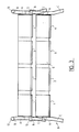
- la Fig. 3 est une vue de profil, à plus grande échelle, de l'empilage de la Fig. 2,
- la Fig. 4 est une vue partielle en élévation d'un empilage de deux variantes d'ensembles selon l'invention, et
- la Fig. 5 est une vue partielle de profil de l'empilage de la Fig. 4.
- Fig. 1 is a plan view of a stackable assembly according to the invention,
- Fig. 2 is an elevational view of a stack of assemblies according to the invention,
- Fig. 3 is a side view, on a larger scale, of the stack of FIG. 2,
- Fig. 4 is a partial view in elevation of a stack of two variant assemblies according to the invention, and
- Fig. 5 is a partial profile view of the stack of FIG. 4.
L'ensemble empilable, montré à la Fig. 1, comporte quatre récipients sous forme de goulottes longitudinales à profil en U, 1 à 4, disposées côte à côte. Les goulottes 1 à 4 sont solidarisées par une plaque avant 5 et une plaque arrière 6. Ces plaques, Figs. 2 et 3, ont leur sommet sensiblement au même niveau que celui des parois latérales des goulottes 1 à 4, mais leur base est légèrement au-dessus des fonds des goulottes, pour permettre l'ecoulement des jus de cuisson. Les goulottes 1 à 4 sont, de préférence, compartimentées par des cloisons transversales 7 ne descendant pas, non plus, jusqu'au fond. Pour des raisons déjà mentionnées, c'est-à-dire la rigidité du dispositif et la répartition optimale de la chaleur, les parois des goulottes externes 1 et 4 sont plus épaisses que celles des goulottes médianes 1 et 2.The stackable assembly, shown in FIG. 1, comprises four containers in the form of longitudinal troughs with U-shaped profile, 1 to 4, arranged side by side. The
A la paroi latérale externe de la goulotte externe 1, sont soudés, près de ses extrémités, les tronçons intermédiaires de deux pieds identiques 8 et 9. De même, à la paroi latérale externe de la goulotte externe 4, sont soudés deux pieds 10 et 11, identiques aux pieds 8 et 9. Vers le haut, les pieds 8 à 11 dépassent de quelques centimètres le sommet des goulottes 1 à 4. Vers le bas, ils dépassent plus nettement la base des goulottes. Dans un exemple de réalisation préféré, les goulottes ont une hauteur de 13 cm et les pieds dépasent, vers le haut, de 6 cm environ et, vers le bas, de 12 cm environ.At the external lateral wall of the
Dans la vue en élévation de la Fig. 2, les pieds 8 à 11 apparaissent tous inclinés longitudinalement, de manière à ce que chaque paire 8, 9 ou 10, 11, de chaque côté, s'évase vers le bas pour rendre l'empilage possible. De préférence, les bases des pieds avant 8 et 10 ne dépassent pas l'avant des goulottes 1 à 4, ni les pieds 9 et 11 l'arrière de celle-ci. En pratique, dans l'exemple de réalisation préféré, les pieds 8 à 11 sont inclinés à environ 15° par rapport à la verticale.In the elevation view of FIG. 2, the
Dans la vue de profil de la Fig. 3, chaque pied, tel que 8, apparaît formé d'un tronçon rectiligne vertical A, dont le sommet coïncide pratiquement avec celui des goulottes 1 à 4 et dont la base est légèrement au dessous du fond des goulottes, un tronçon supérieur B, légèrement incliné vers l'extérieur par rapport à la verticale, et un tronçon inférieur C, également incliné vers l'extérieur par rapport à la verticale, mais de façon plus sensible. Dans l'exemple de réalisation préférée, la partie 8b apparaît inclinée à environ 5° par rapport à la verticale et la partie 8c à 15° environ.In the profile view of FIG. 3, each leg, such as 8, appears to be formed by a vertical rectilinear section A, the top of which practically coincides with that of the
Dans chaque paire de pieds 8, 9 ou 10, 11, les extrémités supérieures des tronçons supérieurs B sont soudées aux extrémités d'une barre longitudinale horizontale 12 ou 13. De préférence, les barres 12, 13 ont une section ronde de diamètre sensiblement égal à l'épaisseur transversale des pieds. Les barres 12 et 13 constituent avec chaque paire de pieds un support latéral; elles donnent de la rigidité à l'ensemble empilable et, de plus, servent de poignées de manipulation.In each pair of
Les faces en regard l'une de l'autres des tronçons intermédiaires A des pieds de chaque paire 8, 9 ou 10, 11 portent des butées 14, 15, Fig. 2, qui sont situées à la même hauteur. Les butées agissent par leurs faces inférieures et, au niveau de celles-ci, la distance entre lesdites faces des pieds de chaque paire est très légèrement supérieure à la longueur des barres 12, 13. Ainsi, quand on empile deux ensembles l'un sur l'autre, les tronçons inférieurs C des pieds de chaque paire 8, 9 et 10, 11 et les butées 14, 15 viennent coiffer et s'appuyer respectivement sur chaque barre 12 et 13 et les tronçons supérieurs B adjacents des pieds de l'ensemble inférieur, l'évasement des pieds dans chaque paire formant un guide longitudinal.The opposite faces of one another of the intermediate sections A of the feet of each
Dans le sens transversal, le tronçon inférieur C de chaque paire de pieds 8, 10 et 9, 11 est également évasé, Fig. 3. A l'empilage, le tronçon C de chaque paire 8,10 et 9, 11 de l'ensemble supérieur vient coiffer, respectivement à l'avant et à l'arrière, les arêtes supérieures externes des goulottes externes 1 et 4. L'évasement du tronçon C de chaque paire, coopérant avec lesdites arêtes forme un guide de positionnement transversal.In the transverse direction, the lower section C of each pair of
Enfin, comme les pieds sont aussi inclinés transversalement vers l'extérieur, à l'empilage, les arêtes externes inférieures des goulottes externes 1 et 4 de l'ensemble supérieur se placent sans coincement possible entre les barres 12 et 13 et les tronçons C des pieds 8 à 11 de l'ensemble inférieur, à mesure que le guidage se fait par les pieds de l'ensemble supérieur et les arêtes inférieures des goulottes externes inférieures.Finally, as the feet are also inclined transversely outwards, when stacking, the lower external edges of the
Comme le montrent les Figs. 2 et 3, la position plus ou moins haute, des butées 14 et 15 sur les tronçons A des pieds déterminent l'écartement vertical, plus ou moins petits entre les goulottes des ensembles empilés. Dans un exemple de réalisation satisfaisant de l'invention, l'écartement entre le sommet des goulottes d'un ensemble et le fond des goulottes de l'ensemble supérieur est d'environ 3 cm.As shown in Figs. 2 and 3, the higher or lower position, the
Dans la variante montrée aux Figs. 4 et 5, sous les fonds des goulottes 1 à 4, seules les goulottes 1 et 2 étant montrées, sont prévues des plaques séparées, telles que 16.1.1, 16.1.2, ..., 16.2.1, ..., 17.1.1, 17.1.2, ..., 17.2.1, ..., qui sont destinées à servir de couvercle pour les compartiments des goulottes immédiatement inférieures dans une empilage.In the variant shown in Figs. 4 and 5, under the bottoms of the
Plus précisément, dans les Figs. 4 et 5, on a représenté un empilage de deux ensembles suivants l'invention. L'ensemble du dessus est muni de plaques 16.i.j, dans lequel i indique le rang de 1 à 4 de la goulotte sous laquelle la plaque est suspendue, et j indique le rang de la plaque sous la goulotte. Si l'on considère que, dans chaque goulotte, les cloisons 7 définissent quatre compartiments, comme le montre la Fig. 1, j varie de 1 à 4. Les intervalles entre les plaques coïncident avec les positions verticales des cloisons 7. Bien entendu, les dimensions hors tout des plaques sont légèrement inférieures à celles d'un compartiment pour pouvoir y pénétrer.More specifically, in Figs. 4 and 5, there is shown a stack of two sets according to the invention. The whole of the top is provided with plates 16.ij, in which i indicates the rank from 1 to 4 of the chute under which the plate is suspended, and j indicates the rank of the plate under the chute. Considering that, in each chute, the
En pratique, chaque plaque, servant de couvercle pour l'ensemble inférieur, est constituée par la base d'une tôle en acier inoxydable pliée en U, les parties verticales du U étant soudées sous le fond de la goulotte. Les Figs. 4 et 5 montrent que, sous les goulottes de l'ensemble supérieur, les parties verticales des tôles en U des plaques 16.i.j sont dans des plans transversaux alors celles des U des plaques 17.i.j de l'ensemble inférieur sont dans des plans longitudinaux. Ainsi, les plaques 16.i.j et leurs retours vers le haut définissent des couloirs de circulation longitudinaux pour les fluides de chauffage ou de refroidissement, alors que les plaques 17.i.j définissent des couloirs de circulation transversaux. Il en résulte une meilleure homogénéité des échanges thermiques.In practice, each plate, serving as a cover for the lower assembly, is constituted by the base of a stainless steel sheet folded in a U, the vertical parts of the U being welded under the bottom of the chute. Figs. 4 and 5 show that, under the troughs of the upper assembly, the vertical parts of the U-shaped sheets of the plates 16.ij are in transverse planes whereas those of the U of the plates 17.ij of the lower assembly are in planes longitudinal. Thus, the plates 16.i.j and their upward returns define longitudinal circulation corridors for the heating or cooling fluids, while the plates 17.i.j define transverse circulation corridors. This results in a better homogeneity of the heat exchanges.
La distance entre les plaques 16.i.j ou 17.i.j des fonds des goulottes correspondantes est telle que celles-ci entrent suffisamment dans les compartiments des goulottes inférieures pour éventuellement presser les produits qui y sont mis à cuire. Dans les Figs. 4 et 5, on a supposé que le pressage était terminé. En pratique, en début de la cuisson, les plaques peuvent être moins entrées dans les goulottes, les butées 14 et 15 ne reposant alors pas sur les barres 12. L'empilage est, à ce moment là, maintenu par des moyens de traction entre, par exemple, les barres de l'étage inférieur et celles de l'étage supérieur de la pile d'ensembles. Au fur et à mesure que les produits cuisent, les plaques descendent dans les goulottes correspondantes.The distance between the plates 16.i.j or 17.i.j of the bottoms of the corresponding chutes is such that these enter the compartments of the lower chutes sufficiently to possibly press the products which are cooked there. In Figs. 4 and 5, it is assumed that the pressing has been completed. In practice, at the start of cooking, the plates can be less entered into the troughs, the
Dans les dispositifs antérieurs, l'écartement entre goulottes voisines était d'environ 0,8 cm. Dans l'exemple de réalisation préféré de l'invention, cet écartement est de 3 cm environ, soit presque quatre fois plus grand.In the previous devices, the spacing between neighboring chutes was about 0.8 cm. In the preferred embodiment of the invention, this spacing is about 3 cm, or almost four times greater.
Claims (10)
Applications Claiming Priority (2)
| Application Number | Priority Date | Filing Date | Title |
|---|---|---|---|
| FR8707108A FR2615484B3 (en) | 1987-05-19 | 1987-05-19 | SUPPORT DEVICE AND ASSOCIATED CONTAINERS FOR LOADING FOOD PRODUCTS, PARTICULARLY HAMS |
| FR8707108 | 1987-05-19 |
Publications (3)
| Publication Number | Publication Date |
|---|---|
| EP0292417A2 true EP0292417A2 (en) | 1988-11-23 |
| EP0292417A3 EP0292417A3 (en) | 1990-01-24 |
| EP0292417B1 EP0292417B1 (en) | 1993-03-31 |
Family
ID=9351283
Family Applications (1)
| Application Number | Title | Priority Date | Filing Date |
|---|---|---|---|
| EP19880460008 Expired - Lifetime EP0292417B1 (en) | 1987-05-19 | 1988-05-06 | Stockable sets of vessels for cooking food |
Country Status (4)
| Country | Link |
|---|---|
| EP (1) | EP0292417B1 (en) |
| DE (1) | DE3879759T2 (en) |
| ES (1) | ES2039687T3 (en) |
| FR (1) | FR2615484B3 (en) |
Cited By (17)
| Publication number | Priority date | Publication date | Assignee | Title |
|---|---|---|---|---|
| FR2663615A1 (en) * | 1990-06-22 | 1991-12-27 | Armor Inox Sa | STACKABLE CONTAINERS FOR CONTAINING FOOD PRODUCTS DURING THEIR COOKING. |
| FR2669004A1 (en) * | 1990-11-09 | 1992-05-15 | Armor Inox Sa | Assembly formed by a frame and a plurality of containers intended to contain food products during their cooking |
| FR2704526A1 (en) * | 1993-04-27 | 1994-11-04 | Armor Inox Sa | Stackable sets of containers for holding food products during cooking. |
| FR2705217A1 (en) * | 1993-05-19 | 1994-11-25 | Armor Inox Sa | Stackable assemblies of containers for containing food products during cooking |
| FR2708449A1 (en) * | 1993-08-06 | 1995-02-10 | Armor Inox Sa | Stackable sets of containers for holding food products during cooking. |
| FR2737645A1 (en) * | 1995-08-11 | 1997-02-14 | Armor Inox Sa | Holder for food products which are pressed during cooking - has vertical side walls with lower inward= and outward=facing horizontal sections, and inner separating panels |
| FR2745984A1 (en) * | 1996-03-18 | 1997-09-19 | Kaufler Sa | UNIT AND INSTALLATION FOR MOLDING AND HEAT TREATMENT OF FOOD PRODUCTS |
| EP0867140A1 (en) | 1997-03-27 | 1998-09-30 | Armor Inox Sa | Press arrangement for stackable frames for molding and cooking food stuff |
| FR2788668A1 (en) | 1999-01-21 | 2000-07-28 | Armor Inox Sa | Ham pressing mould has a movable dividing wall allowing different sized products to be treated |
| FR2788942A1 (en) * | 1999-02-02 | 2000-08-04 | Armor Inox Sa | RIGID STRUCTURE, IN PARTICULAR A STRUCTURE FORMING AN INDUSTRIAL COOKING TOOL. |
| EP1279336A1 (en) * | 2001-07-27 | 2003-01-29 | Armor Inox Sa | Plateau for molding food products |
| FR2827738A1 (en) * | 2001-07-27 | 2003-01-31 | Armor Inox Sa | Molding plate for food products such as ham has troughs of varying cross-section with covers and transverse partitions |
| FR2835706A1 (en) * | 2002-02-14 | 2003-08-15 | Armor Inox Sa | STACKABLE UNIT COMPRISING AT LEAST ONE HONEYCOMB FOR CONTAINING A FOOD PRODUCT SUCH AS HAM |
| US7568581B2 (en) | 2002-02-14 | 2009-08-04 | Armor Inox Sa | Stacking unit comprising at least one chamber for housing a food product such as ham |
| EP2179656A1 (en) | 2008-10-24 | 2010-04-28 | Cremona Inoxidable S.r.l. | System for stacking and unstacking mold units |
| US9609880B2 (en) | 2007-12-05 | 2017-04-04 | The Hillshire Brands Company | System and method for manufacturing and processing a food product |
| WO2018154172A1 (en) | 2017-02-24 | 2018-08-30 | Tecnical Tecnologia Aplicada, Sll | Mould and system for stacking moulds for food products |
Families Citing this family (7)
| Publication number | Priority date | Publication date | Assignee | Title |
|---|---|---|---|---|
| AU8810998A (en) | 1997-07-17 | 1999-02-10 | Kaufler | Device for moulding food products, in particular for cooking ham |
| FR2766063B1 (en) | 1997-07-17 | 1999-10-29 | Kaufler Sa | DEVICE FOR MOLDING FOOD PRODUCTS, PARTICULARLY FOR COOKING HAMS |
| FR2839044B1 (en) * | 2002-04-24 | 2005-04-15 | Armor Inox Sa | DEVICE FOR ARRANGING BETWEEN THEM A PLURALITY OF STACKED CONTAINERS |
| ES2197816B1 (en) | 2002-05-20 | 2005-03-16 | Metalquimia, S.A. | INSTALLATION FOR FOOD COOKING. |
| US7354194B2 (en) | 2003-01-06 | 2008-04-08 | Covidien Ag | Tympanic thermometer probe cover with film support mechanism |
| US7478946B2 (en) * | 2003-01-06 | 2009-01-20 | Covidien Ag | Probe cover cassette with improved probe cover support |
| US20070248141A1 (en) | 2006-04-21 | 2007-10-25 | Sherwood Services Ag | Infrared thermometer and probe cover thereof |
Citations (6)
| Publication number | Priority date | Publication date | Assignee | Title |
|---|---|---|---|---|
| US2310957A (en) * | 1941-05-03 | 1943-02-16 | Hoy Equipment Company | Apparatus for the multiple molding of hams and the like |
| US2503208A (en) * | 1945-03-09 | 1950-04-04 | Singer Mfg Co | Stand for tierable stock boxes |
| US2776071A (en) * | 1952-05-19 | 1957-01-01 | Becker Heinrich | Containers |
| FR2485884A1 (en) * | 1980-07-03 | 1982-01-08 | Armor Inox Sa | Pressing assembly for multilayer set of ham moulds - transmits pressure from moulds in upper layer to covers of moulds in layer below |
| FR2599341A1 (en) * | 1986-05-28 | 1987-12-04 | Armor Inox Sa | Supports and associated containers for loading objects |
| FR2601653A2 (en) * | 1986-05-28 | 1988-01-22 | Armor Inox Sa | Supports and associated containers for the loading of objects |
-
1987
- 1987-05-19 FR FR8707108A patent/FR2615484B3/en not_active Expired
-
1988
- 1988-05-06 EP EP19880460008 patent/EP0292417B1/en not_active Expired - Lifetime
- 1988-05-06 ES ES88460008T patent/ES2039687T3/en not_active Expired - Lifetime
- 1988-05-06 DE DE19883879759 patent/DE3879759T2/en not_active Expired - Lifetime
Patent Citations (6)
| Publication number | Priority date | Publication date | Assignee | Title |
|---|---|---|---|---|
| US2310957A (en) * | 1941-05-03 | 1943-02-16 | Hoy Equipment Company | Apparatus for the multiple molding of hams and the like |
| US2503208A (en) * | 1945-03-09 | 1950-04-04 | Singer Mfg Co | Stand for tierable stock boxes |
| US2776071A (en) * | 1952-05-19 | 1957-01-01 | Becker Heinrich | Containers |
| FR2485884A1 (en) * | 1980-07-03 | 1982-01-08 | Armor Inox Sa | Pressing assembly for multilayer set of ham moulds - transmits pressure from moulds in upper layer to covers of moulds in layer below |
| FR2599341A1 (en) * | 1986-05-28 | 1987-12-04 | Armor Inox Sa | Supports and associated containers for loading objects |
| FR2601653A2 (en) * | 1986-05-28 | 1988-01-22 | Armor Inox Sa | Supports and associated containers for the loading of objects |
Cited By (28)
| Publication number | Priority date | Publication date | Assignee | Title |
|---|---|---|---|---|
| FR2663615A1 (en) * | 1990-06-22 | 1991-12-27 | Armor Inox Sa | STACKABLE CONTAINERS FOR CONTAINING FOOD PRODUCTS DURING THEIR COOKING. |
| EP0463983A1 (en) * | 1990-06-22 | 1992-01-02 | Armor-Inox Sa | Stackable container units for cooking food products |
| FR2669004A1 (en) * | 1990-11-09 | 1992-05-15 | Armor Inox Sa | Assembly formed by a frame and a plurality of containers intended to contain food products during their cooking |
| FR2704526A1 (en) * | 1993-04-27 | 1994-11-04 | Armor Inox Sa | Stackable sets of containers for holding food products during cooking. |
| EP0625325A1 (en) * | 1993-04-27 | 1994-11-23 | Armor Inox Sa | Stackable container units for containing food products during their cooking |
| FR2705217A1 (en) * | 1993-05-19 | 1994-11-25 | Armor Inox Sa | Stackable assemblies of containers for containing food products during cooking |
| FR2708449A1 (en) * | 1993-08-06 | 1995-02-10 | Armor Inox Sa | Stackable sets of containers for holding food products during cooking. |
| EP0638270A1 (en) * | 1993-08-06 | 1995-02-15 | Armor Inox Sa | Stockable sets of vessels for cooking food |
| FR2737645A1 (en) * | 1995-08-11 | 1997-02-14 | Armor Inox Sa | Holder for food products which are pressed during cooking - has vertical side walls with lower inward= and outward=facing horizontal sections, and inner separating panels |
| FR2745984A1 (en) * | 1996-03-18 | 1997-09-19 | Kaufler Sa | UNIT AND INSTALLATION FOR MOLDING AND HEAT TREATMENT OF FOOD PRODUCTS |
| WO1997034494A1 (en) * | 1996-03-18 | 1997-09-25 | Kaufler S.A. | Unit and plant for the moulding and heat treatment of food products |
| US5992304A (en) * | 1996-03-18 | 1999-11-30 | Kaufler S.A. | Apparatus for treatment of food products |
| EP0867140A1 (en) | 1997-03-27 | 1998-09-30 | Armor Inox Sa | Press arrangement for stackable frames for molding and cooking food stuff |
| FR2761250A1 (en) | 1997-03-27 | 1998-10-02 | Armor Inox Sa | PRESSING DEVICE FOR STACKABLE FRAMES FOR MOLDING AND COOKING FOOD PRODUCTS |
| FR2788668A1 (en) | 1999-01-21 | 2000-07-28 | Armor Inox Sa | Ham pressing mould has a movable dividing wall allowing different sized products to be treated |
| FR2788942A1 (en) * | 1999-02-02 | 2000-08-04 | Armor Inox Sa | RIGID STRUCTURE, IN PARTICULAR A STRUCTURE FORMING AN INDUSTRIAL COOKING TOOL. |
| EP1026091A1 (en) * | 1999-02-02 | 2000-08-09 | Armor Inox Sa | Rigid structure, especially structure of industrial cooking device for foodstuffs |
| EP1279336A1 (en) * | 2001-07-27 | 2003-01-29 | Armor Inox Sa | Plateau for molding food products |
| FR2827738A1 (en) * | 2001-07-27 | 2003-01-31 | Armor Inox Sa | Molding plate for food products such as ham has troughs of varying cross-section with covers and transverse partitions |
| FR2827739A1 (en) * | 2001-07-27 | 2003-01-31 | Armor Inox Sa | MOLDING PLATE OF FOOD PRODUCTS |
| US7118368B2 (en) | 2001-07-27 | 2006-10-10 | Armor Inox Sa | Mold table for food products and method of making said table |
| WO2003067993A1 (en) * | 2002-02-14 | 2003-08-21 | Armor Inox Sa | Stacking unit comprising at least one chamber for housing a food product such as ham |
| FR2835706A1 (en) * | 2002-02-14 | 2003-08-15 | Armor Inox Sa | STACKABLE UNIT COMPRISING AT LEAST ONE HONEYCOMB FOR CONTAINING A FOOD PRODUCT SUCH AS HAM |
| US7568581B2 (en) | 2002-02-14 | 2009-08-04 | Armor Inox Sa | Stacking unit comprising at least one chamber for housing a food product such as ham |
| US9609880B2 (en) | 2007-12-05 | 2017-04-04 | The Hillshire Brands Company | System and method for manufacturing and processing a food product |
| EP2179656A1 (en) | 2008-10-24 | 2010-04-28 | Cremona Inoxidable S.r.l. | System for stacking and unstacking mold units |
| EP2179655A1 (en) | 2008-10-24 | 2010-04-28 | Cremona Inoxidable S.r.l. | Stackable mold unit for obtaining a molded cooked food product |
| WO2018154172A1 (en) | 2017-02-24 | 2018-08-30 | Tecnical Tecnologia Aplicada, Sll | Mould and system for stacking moulds for food products |
Also Published As
| Publication number | Publication date |
|---|---|
| FR2615484A1 (en) | 1988-11-25 |
| ES2039687T3 (en) | 1993-10-01 |
| FR2615484B3 (en) | 1989-08-25 |
| DE3879759D1 (en) | 1993-05-06 |
| EP0292417B1 (en) | 1993-03-31 |
| DE3879759T2 (en) | 1993-09-02 |
| EP0292417A3 (en) | 1990-01-24 |
Similar Documents
| Publication | Publication Date | Title |
|---|---|---|
| EP0292417B1 (en) | Stockable sets of vessels for cooking food | |
| FR2519938A1 (en) | STABLE AND GERBABLE CONTAINER WITH THREE LEVELS | |
| EP0625325B1 (en) | Stackable container units for containing food products during their cooking | |
| FR2544058A1 (en) | TRIM MODULE (S) FOR OVEN TROLLEY | |
| WO1997034494A1 (en) | Unit and plant for the moulding and heat treatment of food products | |
| EP0638270B1 (en) | Stockable sets of vessels for cooking food | |
| EP0736247B1 (en) | Trays for producing cheese, process for producing cheese using such trays and device for turning a pile of such trays | |
| CH657975A5 (en) | STORAGE AND EXPOSURE DEVICE. | |
| FR2669004A1 (en) | Assembly formed by a frame and a plurality of containers intended to contain food products during their cooking | |
| EP1152845B1 (en) | Method for assembling sheet metals and rigid structure obtained by said method | |
| EP0463983B1 (en) | Stackable container units for cooking food products | |
| FR2601653A2 (en) | Supports and associated containers for the loading of objects | |
| FR2599341A1 (en) | Supports and associated containers for loading objects | |
| FR2705217A1 (en) | Stackable assemblies of containers for containing food products during cooking | |
| EP0935419B1 (en) | Unit for moulding and hot treatment of elongated food products | |
| FR2731894A1 (en) | Stackable container system for food products during cooking | |
| FR2521110A1 (en) | Bakery proving chamber to hold trays of dough pieces - has side by side lowerer and elevator on top of tray transfer mechanism | |
| FR2468299A1 (en) | Growing tree seedlings in bottomless conical pots - which are supported above surface, with air gap between bottom of pot and surface to discourage root growth through bottom of pot | |
| FR2594434A1 (en) | Device and method for producing humus by means of composting using earthworms | |
| NL8005752A (en) | DEVICE FOR PLANTING OUT OF CROP AND FORMED COMPOSITION. | |
| BE670557A (en) | ||
| FR2648319A1 (en) | Apparatus for cooking and/or heating up by immersion of cooked dishes or products | |
| FR2570351A1 (en) | Tray for holding a plurality of unit containers, method of making such a tray and method of processing a container using such a tray | |
| US10149564B1 (en) | Combined butter stick platform and corn rest | |
| FR2658387A1 (en) | Rigid framework for support and cooking of the "baguette rack" type |
Legal Events
| Date | Code | Title | Description |
|---|---|---|---|
| PUAI | Public reference made under article 153(3) epc to a published international application that has entered the european phase |
Free format text: ORIGINAL CODE: 0009012 |
|
| AK | Designated contracting states |
Kind code of ref document: A2 Designated state(s): BE CH DE ES FR GB IT LI LU NL SE |
|
| PUAL | Search report despatched |
Free format text: ORIGINAL CODE: 0009013 |
|
| AK | Designated contracting states |
Kind code of ref document: A3 Designated state(s): BE CH DE ES FR GB IT LI LU NL SE |
|
| 17P | Request for examination filed |
Effective date: 19900910 |
|
| 17Q | First examination report despatched |
Effective date: 19920709 |
|
| GRAA | (expected) grant |
Free format text: ORIGINAL CODE: 0009210 |
|
| ITF | It: translation for a ep patent filed |
Owner name: BARZANO' E ZANARDO MILANO S.P.A. |
|
| AK | Designated contracting states |
Kind code of ref document: B1 Designated state(s): BE CH DE ES FR GB IT LI LU NL SE |
|
| PG25 | Lapsed in a contracting state [announced via postgrant information from national office to epo] |
Ref country code: SE Effective date: 19930331 |
|
| REF | Corresponds to: |
Ref document number: 3879759 Country of ref document: DE Date of ref document: 19930506 |
|
| GBT | Gb: translation of ep patent filed (gb section 77(6)(a)/1977) |
Effective date: 19930423 |
|
| PG25 | Lapsed in a contracting state [announced via postgrant information from national office to epo] |
Ref country code: LU Free format text: LAPSE BECAUSE OF NON-PAYMENT OF DUE FEES Effective date: 19930531 |
|
| REG | Reference to a national code |
Ref country code: ES Ref legal event code: FG2A Ref document number: 2039687 Country of ref document: ES Kind code of ref document: T3 |
|
| PLBE | No opposition filed within time limit |
Free format text: ORIGINAL CODE: 0009261 |
|
| STAA | Information on the status of an ep patent application or granted ep patent |
Free format text: STATUS: NO OPPOSITION FILED WITHIN TIME LIMIT |
|
| 26N | No opposition filed | ||
| REG | Reference to a national code |
Ref country code: GB Ref legal event code: IF02 |
|
| PGFP | Annual fee paid to national office [announced via postgrant information from national office to epo] |
Ref country code: NL Payment date: 20070514 Year of fee payment: 20 |
|
| PGFP | Annual fee paid to national office [announced via postgrant information from national office to epo] |
Ref country code: CH Payment date: 20070515 Year of fee payment: 20 |
|
| PGFP | Annual fee paid to national office [announced via postgrant information from national office to epo] |
Ref country code: DE Payment date: 20070522 Year of fee payment: 20 |
|
| PGFP | Annual fee paid to national office [announced via postgrant information from national office to epo] |
Ref country code: ES Payment date: 20070529 Year of fee payment: 20 |
|
| PGFP | Annual fee paid to national office [announced via postgrant information from national office to epo] |
Ref country code: BE Payment date: 20070531 Year of fee payment: 20 |
|
| REG | Reference to a national code |
Ref country code: CH Ref legal event code: PFA Owner name: ARMOR-INOX S.A. Free format text: ARMOR-INOX S.A.#16, ROUTE DE DINAN BOITE POSTALE 16#MAURON (FR) -TRANSFER TO- ARMOR-INOX S.A.#16, ROUTE DE DINAN BOITE POSTALE 16#MAURON (FR) |
|
| PGFP | Annual fee paid to national office [announced via postgrant information from national office to epo] |
Ref country code: GB Payment date: 20070522 Year of fee payment: 20 |
|
| PGFP | Annual fee paid to national office [announced via postgrant information from national office to epo] |
Ref country code: IT Payment date: 20070525 Year of fee payment: 20 |
|
| PGFP | Annual fee paid to national office [announced via postgrant information from national office to epo] |
Ref country code: FR Payment date: 20070529 Year of fee payment: 20 |
|
| REG | Reference to a national code |
Ref country code: GB Ref legal event code: PE20 Expiry date: 20080505 |
|
| REG | Reference to a national code |
Ref country code: CH Ref legal event code: PL |
|
| BE20 | Be: patent expired |
Owner name: S.A. *ARMOR-INOX Effective date: 20080506 |
|
| NLV7 | Nl: ceased due to reaching the maximum lifetime of a patent |
Effective date: 20080506 |
|
| REG | Reference to a national code |
Ref country code: ES Ref legal event code: FD2A Effective date: 20080507 |
|
| PG25 | Lapsed in a contracting state [announced via postgrant information from national office to epo] |
Ref country code: ES Free format text: LAPSE BECAUSE OF EXPIRATION OF PROTECTION Effective date: 20080507 Ref country code: NL Free format text: LAPSE BECAUSE OF EXPIRATION OF PROTECTION Effective date: 20080506 |
|
| PG25 | Lapsed in a contracting state [announced via postgrant information from national office to epo] |
Ref country code: GB Free format text: LAPSE BECAUSE OF EXPIRATION OF PROTECTION Effective date: 20080505 |