EP0292200B1 - Composite headlamp bulb retaining mechanism - Google Patents
Composite headlamp bulb retaining mechanism Download PDFInfo
- Publication number
- EP0292200B1 EP0292200B1 EP88304317A EP88304317A EP0292200B1 EP 0292200 B1 EP0292200 B1 EP 0292200B1 EP 88304317 A EP88304317 A EP 88304317A EP 88304317 A EP88304317 A EP 88304317A EP 0292200 B1 EP0292200 B1 EP 0292200B1
- Authority
- EP
- European Patent Office
- Prior art keywords
- retaining ring
- socket structure
- socket
- aperture
- bulb
- Prior art date
- Legal status (The legal status is an assumption and is not a legal conclusion. Google has not performed a legal analysis and makes no representation as to the accuracy of the status listed.)
- Expired - Lifetime
Links
- 230000007246 mechanism Effects 0.000 title claims description 18
- 239000002131 composite material Substances 0.000 title claims description 6
- 230000037431 insertion Effects 0.000 claims description 8
- 238000003780 insertion Methods 0.000 claims description 8
- 230000006835 compression Effects 0.000 claims description 4
- 238000007906 compression Methods 0.000 claims description 4
- 230000000295 complement effect Effects 0.000 claims 2
- 238000009434 installation Methods 0.000 description 1
- 230000014759 maintenance of location Effects 0.000 description 1
- 239000000463 material Substances 0.000 description 1
- 239000002991 molded plastic Substances 0.000 description 1
- 230000000717 retained effect Effects 0.000 description 1
Images

Classifications
-
- F—MECHANICAL ENGINEERING; LIGHTING; HEATING; WEAPONS; BLASTING
- F21—LIGHTING
- F21V—FUNCTIONAL FEATURES OR DETAILS OF LIGHTING DEVICES OR SYSTEMS THEREOF; STRUCTURAL COMBINATIONS OF LIGHTING DEVICES WITH OTHER ARTICLES, NOT OTHERWISE PROVIDED FOR
- F21V19/00—Fastening of light sources or lamp holders
-
- F—MECHANICAL ENGINEERING; LIGHTING; HEATING; WEAPONS; BLASTING
- F21—LIGHTING
- F21S—NON-PORTABLE LIGHTING DEVICES; SYSTEMS THEREOF; VEHICLE LIGHTING DEVICES SPECIALLY ADAPTED FOR VEHICLE EXTERIORS
- F21S41/00—Illuminating devices specially adapted for vehicle exteriors, e.g. headlamps
- F21S41/10—Illuminating devices specially adapted for vehicle exteriors, e.g. headlamps characterised by the light source
- F21S41/19—Attachment of light sources or lamp holders
- F21S41/194—Bayonet attachments
Definitions
- the present invention is directed to the field of lighting components and more specifically to the area of retaining mechanisms for composite headlamp bulbs installed in reflector housings.
- a retaining ring having an internal flange is fixed to a socket contained in a headlamp reflector, and a bulb having a flange with radial tabs is inserted through a correspondingly shaped aperture in the flange and in the socket and rotated so that the flange is clamped between the tabs on the lamp body and a second flange on the lamp body nearer the base of the lamp.
- GB-A-2 064 747 discloses a headlamp in which a retaining ring is fitted into an aperture in the reflector by a bayonet type fitting, the bulb envelope is inserted through apertures in the retaining ring and the reflector so that radial tabs extending from a flange on the body of the bulb fit non-rotatably into recesses in the rear face of the retaining ring, and the tabs are clamped against the retaining ring by a plug that is secured to the ring by snap fittings.
- a mechanism for retaining a composite headlamp bulb comprising a bulb envelope and a body in a reflector housing, said mechanism including an integral socket structure with an aperture for accepting the bulb envelope and a retaining ring having a central aperture aligned with the aperture of the socket structure for accepting the insertion of the bulb body, is characterised in that the socket structure includes a seat for the bulb body and the retaining ring contains integral locking elements for providing a permanent snap fit to the socket structure and a plurality of cantilevered elements configured to engage with the bulb body on insertion and rotation thereof to removably compress the bulb body against the seat in the socket structure.
- the bulb body is formed with a flange having a plurality of tabs extending from its periphery at predetermined positions.
- the aperture of the retaining ring is configured to be sufficiently large for the flange of the bulb body and its tabs to be inserted through the aperture when properly aligned and oriented.
- the flanged bulb body is rotated through a defined angle and the tabs slide beneath a set of cantilevered retaining fingers that extend into the ring aperture from its periphery, where the flange is thereafter retained against the socket opening in a sealed condition to prevent movement or accidental removal from the socket.
- the flanged bulb body can be removed from the retaining ring by overcoming the friction of the retaining fingers on the flange tabs, rotating the bulb body in the opposite direction through the same angle and axially withdrawing the bulb body from the socket through the aperture of the retaining ring.
- the invention provides a retaining ring that is self-latching onto the socket structure so as to eliminate the need for installation tools.
- the retaining ring can only be latched onto the socket structure in a single orientation and the bulb body can only be inserted into the aperture of the ring in a single orientation and rotated to a second single orientation for retention.
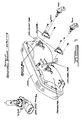
- a sealable reflector housing 10 having a socket aperture 20 and associated structure formed therein to receive an O-ring sealable bulb body therein.
- the socket structure forming the aperture 20 includes a circular sidewall of a diameter appropriate for receiving and compressing the O-ring 53 on the body 55 of bulb 50.
- a larger diametered opening 18 is shown as being concentric with the socket aperture 20 and serves to define the seating surface 19 intermediate thereof.
- the seating surface 19 is that surface to which the flange 52 of the bulb body 55 is compressed against by the retaining ring 30 when the bulb body is inserted and rotated for locking.
- a flange 12 is formed to extend outward from sidewall 18 and is raised from the housing 10 to provide a gripping edge for the retaining ring 30 (see Figure 3).
- the bulb 50 is shown in Figure 1 as supported in a bulb body 55 by a clip element 51.
- the bulb preferrably contains one or more filaments that are electrically connected through the body 55 to an electrical connector 57 located at the opposite end of the body 55.
- the body 55 is formed to have a right angle bend so that electrical connections are made at connector 57, transverse to the socket axis.
- the body 55 also contains a substantially circular flange 52 and a plurality of tabs 54′, 54 ⁇ and 54′′′ radially extending therefrom.
- the flange tabs 54′, 54 ⁇ and 54′′′ are inconsistently sized so that the bulb body 55 may be inserted in the socket in a single orientation.
- Such a single orientation feature is extremely important in the situation where the present invention is employed in automotive headlamp applications. In such applications, there is a strict requirement that the filaments of the bulbs be precisely oriented and postioned within their associated reflectors to provide a prescribed lighting pattern.
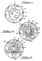
- the retaining ring 30 is preferrably formed of a molded plastic material so that its aligning and locking features may be combined in a unitary structure.
- the retaining ring 30 is circular cup shaped with an cylindrical side wall 33 having an inner diameter that is slightly larger than the diameter of the raised flange 12 on the reflector housing 10.
- a plurality of ramped catch barbs 34 are formed to coextend from the side wall 33. The ramp portions of the catch barbs 34 extend inside the inner diameter dimension of the side wall 33 so as to contact the outer lip 14 adjacent the raised flange 12, when installed thereon.
- An alignment hole 36 is located on the retaining ring 30 to coincide with the alignment pin 16 extending from the socket structure on the reflector housing 10. Therefore, when the retaining ring 30 is installed on the housing 10, the pin 16 is first aligned with the alignment hole 36. Secondly, the ramps of the catch barbs 34 are each positioned to contact the outer lip 14 and the ring is axially forced against the housing 10 until all the catches 34 snap in place behind the raised flange 12. At this point, the retaining ring is permanently installed on the housing 10 and is only removable if several of the catches 34 are forced outwardly from the raised flange 12.
- the retaining ring 30 contains a generally circular aperture that is axially aligned with the socket aperture 20 and has a clearance diameter defined by projecting cantilevered finger elements 32′, 32 ⁇ and 32′′′.
- the clearance diameter is sized to allow the flange 52 of the bulb body 55 pass through, unobstructed.
- the respective cantilevered finger elements 32′, 32 ⁇ and 32′′′ contain ramped surfaces 38′, 38 ⁇ and 38′′′ on the socket side of the ring 30, opposite the insertion direction of the bulb body 55.
- the ramped surfaces extend sufficiently towards the seating surface 19 so that the distance therebetween is less than the thickness of the flange tabs 54′, 54 ⁇ and 54′′′ of the bulb body 55.
- Compression surfaces 40′, 40 ⁇ and 40′′′ are also formed adjacent the ramped surfaces on the respective cantilevered finger elements 32′, 32 ⁇ and 32′′′ so as to provide continuous holding of the flange tabs 54′, 54 ⁇ and 54′′′ against the seating surface 19, when the bulb body 55 is installed.
- the flange tab 54′ When viewed in Figure 5 from the socket side of the retaining ring 30 with the bulb body 55 oriented for insertion through the central aperture, the flange tab 54′ is oriented to pass through the space 39′ defined between cantilevered finger elements 32′ and 32′′′. Similarly, spaces 39 ⁇ and 39′′′ are also provided to respectively pass flange tabs 54 ⁇ and 54′′′.
- the flange tabs are of various sizes to insure a predetermined orientation. Consequently, the spaces between the cantilevered finger elements are of corresponding sizes to profile the flange 52 and its tabs in order to thereby allow the flange 52 and all the tabs to pass through the aperture of the retaining ring 30 when the bulb body 55 is in its proper orientation and alignment with respect to the socket.
Landscapes
- Engineering & Computer Science (AREA)
- General Engineering & Computer Science (AREA)
- Non-Portable Lighting Devices Or Systems Thereof (AREA)
- Fastening Of Light Sources Or Lamp Holders (AREA)
- Connecting Device With Holders (AREA)
Applications Claiming Priority (2)
| Application Number | Priority Date | Filing Date | Title |
|---|---|---|---|
| US07/050,803 US4794500A (en) | 1987-05-18 | 1987-05-18 | Composite headlamp bulb retaining mechanism |
| US50803 | 2002-01-15 |
Publications (3)
| Publication Number | Publication Date |
|---|---|
| EP0292200A2 EP0292200A2 (en) | 1988-11-23 |
| EP0292200A3 EP0292200A3 (en) | 1989-11-02 |
| EP0292200B1 true EP0292200B1 (en) | 1993-09-08 |
Family
ID=21967530
Family Applications (1)
| Application Number | Title | Priority Date | Filing Date |
|---|---|---|---|
| EP88304317A Expired - Lifetime EP0292200B1 (en) | 1987-05-18 | 1988-05-12 | Composite headlamp bulb retaining mechanism |
Country Status (8)
| Country | Link |
|---|---|
| US (1) | US4794500A (enExample) |
| EP (1) | EP0292200B1 (enExample) |
| JP (1) | JPS642201A (enExample) |
| KR (1) | KR960002303B1 (enExample) |
| CA (1) | CA1280730C (enExample) |
| DE (1) | DE3883841T2 (enExample) |
| MX (1) | MX165399B (enExample) |
| NO (1) | NO175502C (enExample) |
Cited By (6)
| Publication number | Priority date | Publication date | Assignee | Title |
|---|---|---|---|---|
| FR2658136A1 (fr) * | 1989-12-15 | 1991-08-16 | Renault | Appareil d'eclairage pour automobiles. |
| EP0468704A1 (en) * | 1990-07-25 | 1992-01-29 | Carello Lighting Plc | Lamp assembly |
| DE9319230U1 (de) * | 1993-12-15 | 1996-01-25 | Forsheda Ab, Forsheda | Muffendichtung für Betonformteile |
| US5515245A (en) * | 1993-07-10 | 1996-05-07 | Hella Kg Hueck & Co. | Apparatus for releasably attaching a lamp on a reflector of a motor vehicle headlight |
| US5775793A (en) * | 1993-06-23 | 1998-07-07 | Robert Bosch Gmbh | Headlight for vehicles |
| GB2339892B (en) * | 1998-07-21 | 2002-02-13 | Certikin Internat Ltd | Halogen light unit |
Families Citing this family (19)
| Publication number | Priority date | Publication date | Assignee | Title |
|---|---|---|---|---|
| US4926301A (en) * | 1986-11-13 | 1990-05-15 | General Motors Corporation | Headlamp assembly |
| US4882660A (en) * | 1986-11-13 | 1989-11-21 | General Motors Corporation | Headlamp assembly |
| US4851976A (en) * | 1989-01-27 | 1989-07-25 | General Motors Corporation | Headlamp bulb retaining arrangement |
| US4947294A (en) * | 1989-04-24 | 1990-08-07 | General Motors Corporation | Headlamp assembly |
| US5010455A (en) * | 1990-05-07 | 1991-04-23 | General Motors Corporation | Headlamp assembly |
| US5251118A (en) * | 1991-08-16 | 1993-10-05 | Devine Lighting, Inc. | Modular lighting system and method |
| US5402325A (en) * | 1993-12-28 | 1995-03-28 | General Motors Corporation | Vehicle headlamp assembly |
| DE4416846A1 (de) * | 1994-05-13 | 1995-11-16 | Hella Kg Hueck & Co | Vorrichtung zur lösbaren Anordnung einer Lampe an einem aus Kunststoff hergestellten Reflektor eines Fahrzeug-Scheinwerfers |
| JP3028742B2 (ja) * | 1995-01-20 | 2000-04-04 | 株式会社小糸製作所 | 車両用灯具 |
| US5722758A (en) * | 1996-04-05 | 1998-03-03 | Grand General Accessories Manufacturing Inc. | Vehicle light fixture with a quick detachable socket |
| US6120167A (en) * | 1998-07-24 | 2000-09-19 | Harley-Davidson Motor Company | Light source assembly for motorcycle tail light |
| DE19843506A1 (de) * | 1998-09-23 | 2000-03-30 | Patent Treuhand Ges Fuer Elektrische Gluehlampen Mbh | Elektrische Lampe |
| US6483258B2 (en) | 2001-01-31 | 2002-11-19 | Honeywell International Inc. | Infrared fiber optic light |
| GB2432364B (en) * | 2005-11-18 | 2009-11-11 | Rohm & Haas Elect Mat | Organometallic compound purification |
| US8109546B2 (en) * | 2009-01-09 | 2012-02-07 | Toyota Motor Engineering & Manufacturing North America, Inc. | Bumper assemblies with independently aligned garnishes and reflectors |
| DE102013104187A1 (de) * | 2013-04-25 | 2014-10-30 | Hella Kgaa Hueck & Co. | Verfahren zur Anordnung eines Halteringes an einem Reflektor |
| JP6191593B2 (ja) * | 2014-12-26 | 2017-09-06 | 東芝ライテック株式会社 | 車両用灯具 |
| DE102021113901A1 (de) * | 2021-05-28 | 2022-12-01 | Carl Freudenberg Kg | Anordnung zur Herstellung einer elektrisch leitfähigen Verbindung zwischen einem ersten Maschinenelement und einem zweiten Maschinenelement |
| DE102024106520A1 (de) * | 2024-03-07 | 2025-09-11 | Dr. Ing. H.C. F. Porsche Aktiengesellschaft | Werkzeug zur Demontage und Montage eines Scheinwerfersicherungselementes und Scheinwerfersicherungseinheit |
Family Cites Families (25)
| Publication number | Priority date | Publication date | Assignee | Title |
|---|---|---|---|---|
| DE344021C (enExample) * | ||||
| US1027306A (en) * | 1911-02-04 | 1912-05-21 | Percy C Avery | Automobile-lamp. |
| US2233486A (en) * | 1939-12-13 | 1941-03-04 | Michael P Portnow | Headlight |
| US2265446A (en) * | 1940-05-18 | 1941-12-09 | Mckee Glass Company | Automobile headlight structure |
| US2748255A (en) * | 1953-05-27 | 1956-05-29 | William E Decker | Automotive vehicle headlight |
| US2750491A (en) * | 1955-02-08 | 1956-06-12 | Northeast Tool Die Works Inc | Sealed beam light |
| US2992323A (en) * | 1959-05-05 | 1961-07-11 | Wheeler Reflector Company | Electric light fixture |
| GB1391704A (en) * | 1972-04-14 | 1975-04-23 | Thorn Electrical Ind Ltd | Lamp pinch seals |
| US4019045A (en) * | 1975-08-25 | 1977-04-19 | General Motors Corporation | Socket mounting cap |
| US4100448A (en) * | 1977-05-02 | 1978-07-11 | General Electric Company | Lamp and socket assembly |
| DE2837280A1 (de) * | 1978-08-25 | 1980-03-06 | Patra Patent Treuhand | Elektrische lampe mit lichtabdeckendem ueberzug |
| US4427255A (en) * | 1979-11-14 | 1984-01-24 | General Electric Company | Plastic based glass halogen lamp |
| FR2474143A1 (fr) * | 1979-12-04 | 1981-07-24 | Cibie Projecteurs | Dispositif de fixation d'une lampe sur le reflecteur d'un projecteur |
| JPS5896606U (ja) * | 1981-12-24 | 1983-06-30 | 市光工業株式会社 | 車輌用前照灯 |
| US4500946A (en) * | 1982-01-13 | 1985-02-19 | Ford Motor Company | Replaceable lamp assembly for a sealable reflector housing |
| US4513356A (en) * | 1982-01-13 | 1985-04-23 | Ford Motor Company | Replaceable lamp assembly and locking mechanism for a sealable reflector housing |
| US4528619A (en) * | 1983-06-24 | 1985-07-09 | Gte Products Corporation | Replaceable lamp unit providing hermetic seal and fixed alignment for electric lamp contained therein and automobile headlight utilizing same |
| US4622486A (en) * | 1983-10-31 | 1986-11-11 | Ichikoh Industries, Limited | Halogen lamp device for headlamp |
| DE3425291A1 (de) * | 1984-07-10 | 1986-01-16 | Robert Bosch Gmbh, 7000 Stuttgart | Scheinwerfer fuer fahrzeuge, insbesondere fuer kraftfahrzeuge |
| US4569006A (en) * | 1985-01-15 | 1986-02-04 | Gte Products Corporation | Replaceable lamp unit and automobile headlight utilizing same |
| US4623958A (en) * | 1985-01-15 | 1986-11-18 | Gte Products Corporation | Replaceable automobile headlight lamp unit |
| US4569005A (en) * | 1985-01-15 | 1986-02-04 | Gte Products Corporation | Replaceable lamp unit and automobile headlight utilizing same |
| US4631651A (en) * | 1985-06-10 | 1986-12-23 | Gte Products Corporation | Replaceable automobile headlight lamp unit and automobile headlight utilizing same |
| DE3602234A1 (de) * | 1986-01-25 | 1987-07-30 | Hella Kg Hueck & Co | Fahrzeugscheinwerfer |
| US4679128A (en) * | 1986-07-24 | 1987-07-07 | General Motors Corporation | Headlamp bulb retaining arrangement |
-
1987
- 1987-05-18 US US07/050,803 patent/US4794500A/en not_active Expired - Lifetime
-
1988
- 1988-05-12 EP EP88304317A patent/EP0292200B1/en not_active Expired - Lifetime
- 1988-05-12 DE DE88304317T patent/DE3883841T2/de not_active Expired - Fee Related
- 1988-05-13 KR KR1019880005600A patent/KR960002303B1/ko not_active Expired - Fee Related
- 1988-05-16 MX MX011499A patent/MX165399B/es unknown
- 1988-05-16 NO NO882150A patent/NO175502C/no not_active IP Right Cessation
- 1988-05-17 JP JP63118415A patent/JPS642201A/ja active Granted
- 1988-05-17 CA CA000567025A patent/CA1280730C/en not_active Expired - Lifetime
Cited By (6)
| Publication number | Priority date | Publication date | Assignee | Title |
|---|---|---|---|---|
| FR2658136A1 (fr) * | 1989-12-15 | 1991-08-16 | Renault | Appareil d'eclairage pour automobiles. |
| EP0468704A1 (en) * | 1990-07-25 | 1992-01-29 | Carello Lighting Plc | Lamp assembly |
| US5775793A (en) * | 1993-06-23 | 1998-07-07 | Robert Bosch Gmbh | Headlight for vehicles |
| US5515245A (en) * | 1993-07-10 | 1996-05-07 | Hella Kg Hueck & Co. | Apparatus for releasably attaching a lamp on a reflector of a motor vehicle headlight |
| DE9319230U1 (de) * | 1993-12-15 | 1996-01-25 | Forsheda Ab, Forsheda | Muffendichtung für Betonformteile |
| GB2339892B (en) * | 1998-07-21 | 2002-02-13 | Certikin Internat Ltd | Halogen light unit |
Also Published As
| Publication number | Publication date |
|---|---|
| KR960002303B1 (ko) | 1996-02-16 |
| KR880014309A (ko) | 1988-12-23 |
| EP0292200A3 (en) | 1989-11-02 |
| NO175502C (no) | 1994-10-19 |
| EP0292200A2 (en) | 1988-11-23 |
| NO175502B (no) | 1994-07-11 |
| US4794500A (en) | 1988-12-27 |
| DE3883841T2 (de) | 1994-01-05 |
| JPH05802B2 (enExample) | 1993-01-06 |
| JPS642201A (en) | 1989-01-06 |
| CA1280730C (en) | 1991-02-26 |
| NO882150L (no) | 1988-11-21 |
| MX165399B (es) | 1992-11-10 |
| DE3883841D1 (de) | 1993-10-14 |
| NO882150D0 (no) | 1988-05-16 |
Similar Documents
| Publication | Publication Date | Title |
|---|---|---|
| EP0292200B1 (en) | Composite headlamp bulb retaining mechanism | |
| US4760506A (en) | Light bulb mounting structure in automotive lamp | |
| CN100430643C (zh) | 安装简易的灯和头灯 | |
| KR100437557B1 (ko) | 접착제없이캡이씌워지는전기램프 | |
| JPH012201A (ja) | 保持機構 | |
| JPH0744051B2 (ja) | 電球のソケット | |
| CN1247375A (zh) | 小型荧光灯泡灯头 | |
| JP5511964B2 (ja) | ランプユニット | |
| US4922388A (en) | Vehicle headlight | |
| US4947294A (en) | Headlamp assembly | |
| GB2064747A (en) | Device for securing a bulb to the reflector of a headlamp | |
| EP0841727B1 (en) | Electric lamp with a variably keyed base | |
| US4851976A (en) | Headlamp bulb retaining arrangement | |
| GB2251484A (en) | Lamp-holder device for vehicle headlamps | |
| EP1008208A1 (en) | Single pin coaxial initiator, retainer and connector and method of operation | |
| US3659093A (en) | Panel indicator lamp assembly | |
| US5651603A (en) | Apparatus for arranging a lamp on a reflector of a vehicle headlight | |
| JP4554339B2 (ja) | 自動車用ヘッドライトの相手部品に光源を装着するための固定システムおよびその方法 | |
| JPH09180506A (ja) | 車両のための前照灯 | |
| JPS6015082B2 (ja) | フランジ付電球を自動車前照灯反射器に取付ける装置 | |
| GB2092736A (en) | Device for Fixing a Bulb on to the Reflector of a Headlamp | |
| JP5536348B2 (ja) | 車両用灯具 | |
| EP0468704B1 (en) | Lamp assembly | |
| US4991067A (en) | Headlamp assembly | |
| JPH0244404Y2 (enExample) |
Legal Events
| Date | Code | Title | Description |
|---|---|---|---|
| PUAI | Public reference made under article 153(3) epc to a published international application that has entered the european phase |
Free format text: ORIGINAL CODE: 0009012 |
|
| AK | Designated contracting states |
Kind code of ref document: A2 Designated state(s): BE DE ES FR GB NL SE |
|
| PUAL | Search report despatched |
Free format text: ORIGINAL CODE: 0009013 |
|
| AK | Designated contracting states |
Kind code of ref document: A3 Designated state(s): BE DE ES FR GB NL SE |
|
| 17P | Request for examination filed |
Effective date: 19900417 |
|
| 17Q | First examination report despatched |
Effective date: 19920622 |
|
| GRAA | (expected) grant |
Free format text: ORIGINAL CODE: 0009210 |
|
| AK | Designated contracting states |
Kind code of ref document: B1 Designated state(s): BE DE ES FR GB NL SE |
|
| PG25 | Lapsed in a contracting state [announced via postgrant information from national office to epo] |
Ref country code: SE Effective date: 19930908 Ref country code: NL Effective date: 19930908 Ref country code: ES Free format text: THE PATENT HAS BEEN ANNULLED BY A DECISION OF A NATIONAL AUTHORITY Effective date: 19930908 Ref country code: BE Effective date: 19930908 |
|
| REF | Corresponds to: |
Ref document number: 3883841 Country of ref document: DE Date of ref document: 19931014 |
|
| ET | Fr: translation filed | ||
| NLV1 | Nl: lapsed or annulled due to failure to fulfill the requirements of art. 29p and 29m of the patents act | ||
| REG | Reference to a national code |
Ref country code: GB Ref legal event code: 746 Effective date: 19940418 |
|
| PLBE | No opposition filed within time limit |
Free format text: ORIGINAL CODE: 0009261 |
|
| STAA | Information on the status of an ep patent application or granted ep patent |
Free format text: STATUS: NO OPPOSITION FILED WITHIN TIME LIMIT |
|
| 26N | No opposition filed | ||
| REG | Reference to a national code |
Ref country code: FR Ref legal event code: D6 |
|
| REG | Reference to a national code |
Ref country code: FR Ref legal event code: TP |
|
| REG | Reference to a national code |
Ref country code: FR Ref legal event code: CD |
|
| PGFP | Annual fee paid to national office [announced via postgrant information from national office to epo] |
Ref country code: DE Payment date: 20010509 Year of fee payment: 14 |
|
| PGFP | Annual fee paid to national office [announced via postgrant information from national office to epo] |
Ref country code: FR Payment date: 20010511 Year of fee payment: 14 |
|
| PGFP | Annual fee paid to national office [announced via postgrant information from national office to epo] |
Ref country code: GB Payment date: 20010529 Year of fee payment: 14 |
|
| REG | Reference to a national code |
Ref country code: GB Ref legal event code: IF02 |
|
| PG25 | Lapsed in a contracting state [announced via postgrant information from national office to epo] |
Ref country code: GB Free format text: LAPSE BECAUSE OF NON-PAYMENT OF DUE FEES Effective date: 20020512 |
|
| PG25 | Lapsed in a contracting state [announced via postgrant information from national office to epo] |
Ref country code: DE Free format text: LAPSE BECAUSE OF NON-PAYMENT OF DUE FEES Effective date: 20021203 |
|
| GBPC | Gb: european patent ceased through non-payment of renewal fee |
Effective date: 20020512 |
|
| PG25 | Lapsed in a contracting state [announced via postgrant information from national office to epo] |
Ref country code: FR Free format text: LAPSE BECAUSE OF NON-PAYMENT OF DUE FEES Effective date: 20030131 |
|
| REG | Reference to a national code |
Ref country code: FR Ref legal event code: ST |