EP0289875A1 - Méthode et dispositif pour le nettoyage des pièces à usiner - Google Patents
Méthode et dispositif pour le nettoyage des pièces à usiner Download PDFInfo
- Publication number
- EP0289875A1 EP0289875A1 EP88106376A EP88106376A EP0289875A1 EP 0289875 A1 EP0289875 A1 EP 0289875A1 EP 88106376 A EP88106376 A EP 88106376A EP 88106376 A EP88106376 A EP 88106376A EP 0289875 A1 EP0289875 A1 EP 0289875A1
- Authority
- EP
- European Patent Office
- Prior art keywords
- workpieces
- washing
- air
- washing container
- container
- Prior art date
- Legal status (The legal status is an assumption and is not a legal conclusion. Google has not performed a legal analysis and makes no representation as to the accuracy of the status listed.)
- Granted
Links
Images

Classifications
-
- B—PERFORMING OPERATIONS; TRANSPORTING
- B08—CLEANING
- B08B—CLEANING IN GENERAL; PREVENTION OF FOULING IN GENERAL
- B08B3/00—Cleaning by methods involving the use or presence of liquid or steam
- B08B3/04—Cleaning involving contact with liquid
- B08B3/10—Cleaning involving contact with liquid with additional treatment of the liquid or of the object being cleaned, e.g. by heat, by electricity or by vibration
- B08B3/102—Cleaning involving contact with liquid with additional treatment of the liquid or of the object being cleaned, e.g. by heat, by electricity or by vibration with means for agitating the liquid
Definitions
- the invention relates to a method for cleaning workpieces from foreign bodies such as chips or the like. by washing with a washing liquid in a washing container while blowing in compressed air or the like. below the workpieces, as well as a device for performing the method.
- washing liquid usually consists of water with cleaning additives, and the washing liquid in the washing container is pumped or the like to get to all surfaces, recesses, bores, etc. of the workpieces. kept moving.
- foreign bodies such as chips can only be removed from angled bores and blind holes with great difficulty, so that manual subsequent cleaning using suitable brushes or cleaning syringes and using compressed air is usually used.
- Such manual post-cleaning is, however, associated with great effort and nevertheless does not provide sufficient certainty that the machined parts are free of chips and other foreign bodies, which can have an extremely disadvantageous effect, in particular when parts slide or move later in operation.
- Examples of such difficult-to-clean workpieces include engine blocks, cylinder heads, oil pump and water pump housings, intake manifolds and other parts from the automotive industry, which are particularly difficult to clean due to their complicated shape with a large number of tortuous channels, chambers, through and blind holes are, which has a particularly disadvantageous effect in series production.
- the present invention has for its object a method and an apparatus for cleaning workpieces from foreign bodies such as chips or the like. preferred suggest that, even with complicated shapes of the workpieces, allows a flawless, largely automatic cleaning without the need for manual subsequent cleaning.
- washing liquid is pumped in via an inlet arranged in the lower region of the washing container and pumped out via an overflow of the washing container, and that in the region of the inlet the compressed air or the like . is introduced.
- the invention evaluates the property of air or other gases to have a greater affinity for solids than for water or liquids, ie that the air (or gas) has the property of blowing into the wash liquid the foreign bodies in the bores, depressions and the like. bind the workpieces and rise due to the buoyancy forces in the washing liquid.
- the inventive concept described above already leads to an extremely good cleaning of the workpieces.
- the general principle of the use of rising air in the wash water can be used particularly advantageously in the case of particularly inaccessible and branched channels in the workpieces if, according to a further feature of the invention, the workpieces are moved in the wash tank about an approximately horizontal axis in such a way that in the Workpieces existing bores, channels or other recesses compared to the horizontal with their Openings are directed downwards or upwards in succession and the air or the like blown in below the workpieces. penetrates into the bores, channels or other depressions of the workpieces directed downward in the course of the rotation of the workpieces and thereafter or the like in the course of the further rotation while entraining the chips. flows out again.
- This principle can be used both in a cleaning process with a detergent circuit circulated via an overflow and without one.
- cavities and chambers such as e.g. Blind holes in the workpieces with their opening directed downwards at a certain point in time, so that the blown-in air rises into the blind holes, binds to the foreign bodies and, when the workpiece continues to rotate, z. B. 180 ° out of the then upward opening from the blind hole by buoyancy.
- This combination of measures achieves an extraordinarily high cleaning effect; this effect is of course also given with through holes and channels.
- the invention also relates to a device for carrying out the method according to the invention.
- a device for carrying out the method according to the invention is characterized by a gear head arranged in the washing container, to which the workpieces can be fastened and which for generating movement of the workpieces at least about an approximately horizontal axis, in particular in the form of a wobble movement, is formed.
- the gear head preferably has at least one gripping device for releasably holding a workpiece. By means of such a gripping device, the workpieces can be gripped manually or automatically in series production, immersed in the washing container and moved in the manner indicated.
- the movement of the workpiece or workpieces must take place at least about an approximately horizontal axis, so that bores and chambers with only one access opening for entry of the blown-in air downwards and for discharging the air with foreign bodies bound to them are directed upwards by buoyancy.
- a particularly advantageous embodiment of the invention is characterized in that a separating device, in particular a sieve, is preferably provided on an overflow of the washing container in order to continuously remove the foreign bodies from the circuit of the washing liquid.
- the air blown in can expediently be injected into the inlet.
- a particularly advantageous embodiment of the device according to the invention in which a movement of the workpiece about an at least horizontal axis in In most cases, this is not necessary, characterized in that the inlet at the bottom of the washing container is in the form of a plurality of water nozzles, and that compressed air or another gas is introduced via air nozzles arranged between the water nozzles, in such a way that an even one Water flow with finely divided air bubbles results essentially without swirling from bottom to top past the workpieces arranged in the washing container.
- the workpiece will be moved around at least the horizontal axis.
- a particularly simple construction of this embodiment is characterized in that the washing container has an intermediate floor, in which the water nozzles are arranged at regular intervals and in which air holes are provided between the water nozzles at uniform, finer intervals, and in that the intermediate space under the intermediate floor connects to one Compressed air source can be connected.
- a further advantageous embodiment is characterized in that a magnetic separator in the form of a magnetic conveyor belt is provided at the bottom of the washing container, through which the magnetically attracted foreign bodies are conveyed to the outside.
- vibration generator act on the workpiece immersed in the washing container, which generator either vibrates the workpiece itself or the washing liquid.
- this consists of an outer container and a basket suspended therein with walls designed as a sieve.
- This basket can be removed and cleaned at greater intervals after moving the gear head away from the outer container in order to avoid plugging or swirling with foreign bodies.
- the device for washing workpieces shown schematically in section in FIG. 1, consists of an outer container 1 and a basket 2 suspended in it, which has walls formed as a sieve.
- the outer container 1 and the basket 2 form a washing container.
- the washing container 1, 2 is filled with a washing liquid 20 which is fed to the bottom 19 of the outer container 1 via an inlet by means of a circulation pump 12 and is returned to the pump via an outlet 11 in the upper region of the outer container 1.
- the drain 11 is arranged in the area of an overflow 8 on the basket 2 of the washing container.
- a separator is in the form of the overflow 8 a sieve 9 is provided in order not to let rinsed foreign bodies into the outlet 11, and thus into the circuit of the washing water.
- a gear head 5 is suspended on the outer container 1 by means of a cross member 22 and by means of a holder 21, which (in the present case) has two gripping devices 3 for holding a workpiece 4 each.
- the gear head 5 is designed such that it exerts a wobbling movement on the workpieces 4, i.e. a multidimensional movement about several axes, of which the horizontal axis 6 and the vertical axis 7 are indicated in FIG. 1. It is important for such a wobble movement or other movement about several axes that each of the workpieces 4 executes such a movement in the washing container that each surface or opening of the workpieces successively one after the other essentially downwards and once essentially upwards shows.
- An air line 13 is introduced into the inlet 10 for the washing liquid and compressed air is supplied via a blower 14.
- This injected compressed air rises in the form of air bubbles in the washing liquid, that is, it passes through the bottom of the basket 2 into the area of the workpieces 4. Since the air or another gas is larger with respect to solids, such as the foreign bodies to be removed Affinity as compared to the washing liquid 20, the air bubbles adhere to the foreign bodies and tear them up due to the buoyancy. They also climb into downward openings in bores and channels or the like in the workpieces.
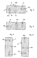
- Fig. 2 shows another embodiment of the device according to the invention in partial view.
- a plurality of nozzles is arranged, to which compressed air is fed from the blower 14 via the air line 13.
- compressed air is fed from the blower 14 via the air line 13.
- a workpiece 4 is now shown in different positions in order to explain the effect of the method according to the invention.
- the workpiece 4 has a multiplicity of bores, channels or other depressions 15a, 15b and 15c which are connected to the outer surfaces of the workpiece via openings 16.
- In these holes or the like 15 there are schematically indicated foreign substances 17 such as chips from a previous machining production process.
- the blind bore 15a is now open at the top, so that the air bubbles with the foreign bodies bound to them can escape upwards through buoyancy.
- the through hole 15b is concerned, any foreign bodies still hanging on the unevenness of the walls have the opportunity to rise from the through hole in the opposite direction. Practically nothing has changed with regard to the blind bore 15c lying on the side.
- the air bubbles can move into the position shown in FIG. 3 and 4 ascend lateral blind hole 15c, bind foreign bodies and collect in the upper end of blind hole 15c.
- the air bubbles with the foreign bodies can leave the blind bore 15c which is now pointing upwards.
- each hole, in particular blind hole or each channel is positioned one after the other in such a way that air bubbles can get in and then get out again by buoyancy.
- the affinity of the air bubbles for the foreign bodies, in particular metal chips, is so great that the bores, cavities or the like. of the workpieces 4 in a relatively short time, i.e. after a few revolutions of the gear head, are rinsed free, so that the workpieces can be used without further manual cleaning.
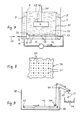
- FIGS. 7 and 8 The further device according to the invention shown in FIGS. 7 and 8 has the following differences compared to the embodiments described above:
- An inner container 30 with an overflow 8 is arranged in a closed outer container 1. Via an inlet 10, washing liquid 20 is pumped in via pump nozzles 31 in the direction of the arrow by means of a pump 12, and the washing liquid overflowing via the overflow 8 is pumped out again via an outlet 11.
- the foreign bodies 17 overflowing with the overflow 8 are collected in a sieve 9 and removed from there in a suitable manner.
- Compressed air 39 is supplied via an air line 13 and passes via air nozzles 33 between the water nozzles 31 into the lower part of the inner container 30.
- the water nozzles 31 and the air nozzles 33 are arranged in the lower part of the inner container 30 in the following way: In the lower region of the inner container 30, an intermediate base 34 is drawn in, which creates an intermediate space 32 between itself and the base 19 of the inner container. A large number of water nozzles 31 are arranged in the intermediate floor 34 (see in particular FIG. 8) at regular intervals, and air nozzles 33, which are designed as fine bores in the intermediate floor 34, are provided evenly between them in a finer grid.
- the water nozzles 31 are structurally in the form of nozzle tubes arranged in the intermediate floor 34, which are connected to the inlet 10.
- the air nozzles 33 in the form of fine bores are supplied with compressed air from the air line 13 via the intermediate space 32.
- the uniform and alternating arrangement of the water nozzles 31 and the air nozzles 33 results in a relatively uniform water flow with finely distributed air bubbles in the inner container 30 from bottom to top, with hardly any swirling. This uniform water-air flow sweeps past the workpiece 4 and tears up foreign matter such as chips from its surface.
- the workpiece 4 is shown in Fig. 7 only schematically hanging on a bracket 21. If there are workpieces that do not have blind holes, it is not necessary to give the workpiece 4 a movement rotating about a horizontal axis (as in the exemplary embodiments described above), but the uniform ascending water-air flow is sufficient, to achieve a sufficient cleaning effect. However, if the workpiece 4 has blind holes or other inaccessible channels, the workpiece is expediently rotated about a horizontal axis, or it is allowed to perform a wobbling movement.
- a further improvement in the cleaning effect can be achieved in that (see FIG. 7) a vibration generator 46 is provided, which acts on the workpiece 4 immersed in the washing liquid 20.
- This vibration generator 46 can either be coupled directly to the workpiece or is arranged at a suitable location in the washing container.
- FIG. 9 is particularly suitable for removing steel and iron chips from the washing container. While, for example, aluminum chips are almost entirely removed via the overflow 8 by the rising water-air mixture, it can also be the case with steel or iron chips come that they fall to the bottom of the washing container 40 and must be removed from there from time to time.
- a magnetic conveyor belt 42 is provided in the floor area, which is guided over suitably arranged deflection rollers 41 and driven in a corresponding manner.
- the foreign bodies present on the magnetic conveyor belt 42 are attracted to the magnetic conveyor belt 42 and are guided outwards over the edge of the washing container.
- a wiping lip 45 wipes off the foreign bodies 17 so that they fall into a collecting container 44.
- corresponding water nozzles 31 and air nozzles 33 are of course provided above the magnetic conveyor belt 42, as in the exemplary embodiments described above, or corresponding similar parts are arranged according to the embodiments according to FIGS. 1 and 2.
- these parts must be permeable to the falling foreign bodies 17, which in the case of the water nozzles 31 and air nozzles 33 shown in FIG. 7 can be designed in such a way that the air nozzles 33 are also designed in the form of interconnected air tubes with nozzles.
Priority Applications (1)
| Application Number | Priority Date | Filing Date | Title |
|---|---|---|---|
| JP11340888A JPS6447485A (en) | 1987-05-08 | 1988-05-09 | Method for washing processed member |
Applications Claiming Priority (2)
| Application Number | Priority Date | Filing Date | Title |
|---|---|---|---|
| DE19873715332 DE3715332A1 (de) | 1987-05-08 | 1987-05-08 | Verfahren und vorrichtung zum reinigen von werkstuecken |
| DE3715332 | 1987-05-08 |
Publications (2)
| Publication Number | Publication Date |
|---|---|
| EP0289875A1 true EP0289875A1 (fr) | 1988-11-09 |
| EP0289875B1 EP0289875B1 (fr) | 1991-07-10 |
Family
ID=6327090
Family Applications (1)
| Application Number | Title | Priority Date | Filing Date |
|---|---|---|---|
| EP88106376A Expired - Lifetime EP0289875B1 (fr) | 1987-05-08 | 1988-04-21 | Méthode et dispositif pour le nettoyage des pièces à usiner |
Country Status (2)
| Country | Link |
|---|---|
| EP (1) | EP0289875B1 (fr) |
| DE (2) | DE3715332A1 (fr) |
Cited By (16)
| Publication number | Priority date | Publication date | Assignee | Title |
|---|---|---|---|---|
| US5071488A (en) * | 1988-07-29 | 1991-12-10 | Texas Instruments Incorporated | Method for subjecting an object to a liquid treatment |
| DE9300476U1 (fr) * | 1993-01-15 | 1993-04-08 | Voelkl, Thomas, 8206 Bruckmuehl, De | |
| EP0543322A1 (fr) * | 1991-11-22 | 1993-05-26 | Aichelin Gmbh | Procédé pour le nettoyage des parts métalliques |
| EP0543318A1 (fr) * | 1991-11-22 | 1993-05-26 | Aichelin Gmbh | Procédé et dispositif pour le nettoyage des parts métalliques |
| EP0607974A1 (fr) * | 1993-01-21 | 1994-07-27 | Uchinami Co.,Ltd. | Procédé et dispositif de nettoyage sous-marin |
| EP0613734A1 (fr) * | 1993-03-05 | 1994-09-07 | France Telecom | Procédé et appareil pour le dégraissage d'un câble à fibres optiques |
| GB2278047A (en) * | 1993-05-22 | 1994-11-23 | Karim Justin Mezeli | Paint brush cleaning |
| EP0667191A1 (fr) * | 1994-02-11 | 1995-08-16 | France Telecom | Dispositif de dégraissage notamment pour fibres optiques |
| EP0675528A2 (fr) * | 1994-03-28 | 1995-10-04 | Shin-Etsu Handotai Company Limited | Méthode de rinçage de substrats et dispositif de rinçage |
| WO1996004083A1 (fr) * | 1994-08-01 | 1996-02-15 | B & S Research | Procede et appareil de traitement des materiaux contamines |
| EP0709120A1 (fr) * | 1994-03-31 | 1996-05-01 | Eiichi Sugiura | Dispositif de lavage, separateur d'eau huileuse et dispositif de filtrage con u pour le dispositif de lavage |
| WO1996021525A2 (fr) * | 1995-01-10 | 1996-07-18 | Wuebbe Roland | Installation et procede permettant de laver de la terre contaminee ou des materiaux similaires et de nettoyer des pieces d'equipements ou des composants similaires entrant en contact avec des fluides |
| EP1188540A2 (fr) * | 2000-09-19 | 2002-03-20 | Fuji Photo Film Co., Ltd. | Méthode de recyclage pour produits en polymères et procédé avec un dispositif pour laver une matière plastique fractionnée |
| EP1201324A2 (fr) * | 2000-10-18 | 2002-05-02 | Siemens Canada Limited | Dispositif pour laver des collecteurs d'admission au moyen de turbulences et de bulles d'air dans un liquide de lavage |
| CN100464877C (zh) * | 2006-02-23 | 2009-03-04 | 博奥生物有限公司 | 一种芯片洗涤装置 |
| CN117102145A (zh) * | 2023-10-24 | 2023-11-24 | 湘潭电化科技股份有限公司 | 一种二氧化锰细颗粒漂洗装置 |
Families Citing this family (1)
| Publication number | Priority date | Publication date | Assignee | Title |
|---|---|---|---|---|
| CN106334688A (zh) * | 2016-08-29 | 2017-01-18 | 桂林福达全州高强度螺栓有限公司 | 一种产品表面处理的气泡清洗装置 |
Citations (4)
| Publication number | Priority date | Publication date | Assignee | Title |
|---|---|---|---|---|
| DE2444161A1 (de) * | 1974-09-16 | 1976-04-01 | Duerr O Fa | Verfahren und anlage zum waschen von werkstuecken, insbesondere metallteilen |
| FR2378577A1 (fr) * | 1977-01-28 | 1978-08-25 | Fontana Giancarlo | Procede et appareil de lavage, notamment pour fruits et legumes |
| US4305413A (en) * | 1980-07-25 | 1981-12-15 | Ecology, Inc. | Cleaning apparatus |
| DE8437870U1 (de) * | 1984-12-22 | 1986-02-13 | Wache Oberflächentechnik GmbH & Co KG, 2000 Norderstedt | Vorrichtung zum Waschen von vorzugsweise metallischen Werkstücken |
-
1987
- 1987-05-08 DE DE19873715332 patent/DE3715332A1/de not_active Withdrawn
-
1988
- 1988-04-21 EP EP88106376A patent/EP0289875B1/fr not_active Expired - Lifetime
- 1988-04-21 DE DE8888106376T patent/DE3863582D1/de not_active Expired - Fee Related
Patent Citations (4)
| Publication number | Priority date | Publication date | Assignee | Title |
|---|---|---|---|---|
| DE2444161A1 (de) * | 1974-09-16 | 1976-04-01 | Duerr O Fa | Verfahren und anlage zum waschen von werkstuecken, insbesondere metallteilen |
| FR2378577A1 (fr) * | 1977-01-28 | 1978-08-25 | Fontana Giancarlo | Procede et appareil de lavage, notamment pour fruits et legumes |
| US4305413A (en) * | 1980-07-25 | 1981-12-15 | Ecology, Inc. | Cleaning apparatus |
| DE8437870U1 (de) * | 1984-12-22 | 1986-02-13 | Wache Oberflächentechnik GmbH & Co KG, 2000 Norderstedt | Vorrichtung zum Waschen von vorzugsweise metallischen Werkstücken |
Cited By (29)
| Publication number | Priority date | Publication date | Assignee | Title |
|---|---|---|---|---|
| US5071488A (en) * | 1988-07-29 | 1991-12-10 | Texas Instruments Incorporated | Method for subjecting an object to a liquid treatment |
| EP0543322A1 (fr) * | 1991-11-22 | 1993-05-26 | Aichelin Gmbh | Procédé pour le nettoyage des parts métalliques |
| EP0543318A1 (fr) * | 1991-11-22 | 1993-05-26 | Aichelin Gmbh | Procédé et dispositif pour le nettoyage des parts métalliques |
| DE9300476U1 (fr) * | 1993-01-15 | 1993-04-08 | Voelkl, Thomas, 8206 Bruckmuehl, De | |
| EP0607974A1 (fr) * | 1993-01-21 | 1994-07-27 | Uchinami Co.,Ltd. | Procédé et dispositif de nettoyage sous-marin |
| US5418884A (en) * | 1993-03-05 | 1995-05-23 | France Telecom | Process and apparatus for degreasing a fiber-optic cable |
| FR2702282A1 (fr) * | 1993-03-05 | 1994-09-09 | Caudrelier Jacques | Procédé et appareil pour le dégraissage d'un câble à fibres optiques. |
| EP0613734A1 (fr) * | 1993-03-05 | 1994-09-07 | France Telecom | Procédé et appareil pour le dégraissage d'un câble à fibres optiques |
| GB2278047A (en) * | 1993-05-22 | 1994-11-23 | Karim Justin Mezeli | Paint brush cleaning |
| EP0667191A1 (fr) * | 1994-02-11 | 1995-08-16 | France Telecom | Dispositif de dégraissage notamment pour fibres optiques |
| FR2716267A1 (fr) * | 1994-02-11 | 1995-08-18 | Crespel Daniel | Dispositif de dégraissage notamment pour fibres optiques. |
| EP0675528A2 (fr) * | 1994-03-28 | 1995-10-04 | Shin-Etsu Handotai Company Limited | Méthode de rinçage de substrats et dispositif de rinçage |
| US5881748A (en) * | 1994-03-28 | 1999-03-16 | Shin-Etsu Handotai Co. Ltd. | Apparatus for rinsing wafers adhered with chemical liquid by use of purified water |
| EP0675528A3 (fr) * | 1994-03-28 | 1997-05-28 | Shinetsu Handotai Kk | Méthode de rinçage de substrats et dispositif de rinçage. |
| EP0709120A1 (fr) * | 1994-03-31 | 1996-05-01 | Eiichi Sugiura | Dispositif de lavage, separateur d'eau huileuse et dispositif de filtrage con u pour le dispositif de lavage |
| EP0709120A4 (fr) * | 1994-03-31 | 1997-03-19 | Eiichi Sugiura | Dispositif de lavage, separateur d'eau huileuse et dispositif de filtrage con u pour le dispositif de lavage |
| US5709234A (en) * | 1994-08-01 | 1998-01-20 | B&S Research, Inc. | Method and apparatus for remediating contaminated material |
| WO1996004083A1 (fr) * | 1994-08-01 | 1996-02-15 | B & S Research | Procede et appareil de traitement des materiaux contamines |
| WO1996021525A2 (fr) * | 1995-01-10 | 1996-07-18 | Wuebbe Roland | Installation et procede permettant de laver de la terre contaminee ou des materiaux similaires et de nettoyer des pieces d'equipements ou des composants similaires entrant en contact avec des fluides |
| WO1996021525A3 (fr) * | 1995-01-10 | 1996-09-19 | Roland Wuebbe | Installation et procede permettant de laver de la terre contaminee ou des materiaux similaires et de nettoyer des pieces d'equipements ou des composants similaires entrant en contact avec des fluides |
| EP1188540A2 (fr) * | 2000-09-19 | 2002-03-20 | Fuji Photo Film Co., Ltd. | Méthode de recyclage pour produits en polymères et procédé avec un dispositif pour laver une matière plastique fractionnée |
| EP1188540A3 (fr) * | 2000-09-19 | 2002-06-05 | Fuji Photo Film Co., Ltd. | Méthode de recyclage pour produits en polymères et procédé avec un dispositif pour laver une matière plastique fractionnée |
| US6846441B2 (en) | 2000-09-19 | 2005-01-25 | Fuji Photo Film Co., Ltd. | Method for recycling used-up plastic products and washing process of crushed plastic and apparatus therefor |
| US7231927B2 (en) | 2000-09-19 | 2007-06-19 | Fujifilm Corporation | Method for recycling used-up plastic products and washing process of crushed plastic and apparatus therefor |
| EP1201324A2 (fr) * | 2000-10-18 | 2002-05-02 | Siemens Canada Limited | Dispositif pour laver des collecteurs d'admission au moyen de turbulences et de bulles d'air dans un liquide de lavage |
| EP1201324A3 (fr) * | 2000-10-18 | 2003-10-29 | Siemens Canada Limited | Dispositif pour laver des collecteurs d'admission au moyen de turbulences et de bulles d'air dans un liquide de lavage |
| CN100464877C (zh) * | 2006-02-23 | 2009-03-04 | 博奥生物有限公司 | 一种芯片洗涤装置 |
| CN117102145A (zh) * | 2023-10-24 | 2023-11-24 | 湘潭电化科技股份有限公司 | 一种二氧化锰细颗粒漂洗装置 |
| CN117102145B (zh) * | 2023-10-24 | 2024-02-13 | 湘潭电化科技股份有限公司 | 一种二氧化锰细颗粒漂洗装置 |
Also Published As
| Publication number | Publication date |
|---|---|
| EP0289875B1 (fr) | 1991-07-10 |
| DE3715332A1 (de) | 1988-12-01 |
| DE3863582D1 (de) | 1991-08-14 |
Similar Documents
| Publication | Publication Date | Title |
|---|---|---|
| EP0289875B1 (fr) | Méthode et dispositif pour le nettoyage des pièces à usiner | |
| DE3127440C2 (fr) | ||
| DE102015116196B3 (de) | Wasch- und/oder Reinigungsanlage | |
| EP0654294A2 (fr) | Procédé et dispositif de filtration de particules solides de liquides et le rinçage du filtre à contre-courant | |
| DE2324233A1 (de) | Luftreinigungsvorrichtung | |
| DE102006017488B3 (de) | Hub-Tauchanlage | |
| EP1967296B1 (fr) | Dispositif de nettoyage de caisses et sol correspondant | |
| EP0712688A2 (fr) | Machine à ébavurer, satiner et polir avec entraînement à bande | |
| DE3702675C2 (fr) | ||
| DE3014542A1 (de) | Vorrichtung zur allseitigen behandlung von dieselbe kontinuierlich durchlaufenden werkstuecken | |
| DE4401181A1 (de) | Vorrichtung zur Reinigung von in Abwassern enthaltenen Feststoffen | |
| DE4443583C2 (de) | Verfahren und Vorrichtung zum Reinigen und/oder Trocknen von Werkstücken | |
| WO2007090637A1 (fr) | Procédé et dispositif de nettoyage de pièces | |
| EP0569749B1 (fr) | Dispositif de nettoyage à lit vibrant pour copeaux métalliques graissés | |
| DE19914746A1 (de) | Ultraschallwaschvorrichtung und Ultraschallwaschsystem | |
| EP0988825A2 (fr) | Filtre à tamis pour machine assurant le deplacement de liquide | |
| DE4315633C2 (de) | Mobile Einrichtung zum Reinigen von verschmutzten Teilen aus Produktionsbetrieben | |
| DE2353266A1 (de) | Verfahren und vorrichtung zum reinigen kleiner holzteile wie hackschnitzel | |
| EP1105030B1 (fr) | Dispositif de nettoyage | |
| DE1546073A1 (de) | Verfahren und Vorrichtung zum Waschen und Entfetten von Gegenstaenden | |
| DD236910A1 (de) | Vorrichtung zum foerdern von flaschen durch flaschenreinigungsmaschinen | |
| EP0569108A1 (fr) | Dispositif pour purifier des huiles lubrifiantes de refroidissement | |
| DE277842C (fr) | ||
| DE1610894A1 (de) | Verfahren und Einrichtung zum Klaeren eines zur chemischen Reinigung dienenden Loesungsmittels | |
| DE3623869A1 (de) | Vorrichtung zum gleitschleifen von werkstuecken |
Legal Events
| Date | Code | Title | Description |
|---|---|---|---|
| PUAI | Public reference made under article 153(3) epc to a published international application that has entered the european phase |
Free format text: ORIGINAL CODE: 0009012 |
|
| AK | Designated contracting states |
Kind code of ref document: A1 Designated state(s): DE FR GB IT SE |
|
| 17P | Request for examination filed |
Effective date: 19881122 |
|
| 17Q | First examination report despatched |
Effective date: 19890529 |
|
| GRAA | (expected) grant |
Free format text: ORIGINAL CODE: 0009210 |
|
| AK | Designated contracting states |
Kind code of ref document: B1 Designated state(s): DE FR GB IT SE |
|
| PG25 | Lapsed in a contracting state [announced via postgrant information from national office to epo] |
Ref country code: IT Free format text: LAPSE BECAUSE OF FAILURE TO SUBMIT A TRANSLATION OF THE DESCRIPTION OR TO PAY THE FEE WITHIN THE PRE;WARNING: LAPSES OF ITALIAN PATENTS WITH EFFECTIVE DATE BEFORE 2007 MAY HAVE OCCURRED AT ANY TIME BEFORE 2007. THE CORRECT EFFECTIVE DATE MAY BE DIFFERENT FROM THE ONE RECORDED.SCRIBED TIME-LIMIT Effective date: 19910710 Ref country code: GB Effective date: 19910710 Ref country code: SE Effective date: 19910710 |
|
| REF | Corresponds to: |
Ref document number: 3863582 Country of ref document: DE Date of ref document: 19910814 |
|
| EN | Fr: translation not filed | ||
| PG25 | Lapsed in a contracting state [announced via postgrant information from national office to epo] |
Ref country code: FR Effective date: 19911129 |
|
| GBV | Gb: ep patent (uk) treated as always having been void in accordance with gb section 77(7)/1977 [no translation filed] | ||
| PLBE | No opposition filed within time limit |
Free format text: ORIGINAL CODE: 0009261 |
|
| STAA | Information on the status of an ep patent application or granted ep patent |
Free format text: STATUS: NO OPPOSITION FILED WITHIN TIME LIMIT |
|
| 26N | No opposition filed | ||
| REG | Reference to a national code |
Ref country code: FR Ref legal event code: ST |
|
| PGFP | Annual fee paid to national office [announced via postgrant information from national office to epo] |
Ref country code: DE Payment date: 19950425 Year of fee payment: 8 |
|
| PG25 | Lapsed in a contracting state [announced via postgrant information from national office to epo] |
Ref country code: DE Effective date: 19970101 |