EP0289875A1 - Method and device for cleaning work pieces - Google Patents
Method and device for cleaning work pieces Download PDFInfo
- Publication number
- EP0289875A1 EP0289875A1 EP88106376A EP88106376A EP0289875A1 EP 0289875 A1 EP0289875 A1 EP 0289875A1 EP 88106376 A EP88106376 A EP 88106376A EP 88106376 A EP88106376 A EP 88106376A EP 0289875 A1 EP0289875 A1 EP 0289875A1
- Authority
- EP
- European Patent Office
- Prior art keywords
- workpieces
- washing
- air
- washing container
- container
- Prior art date
- Legal status (The legal status is an assumption and is not a legal conclusion. Google has not performed a legal analysis and makes no representation as to the accuracy of the status listed.)
- Granted
Links
Images

Classifications
-
- B—PERFORMING OPERATIONS; TRANSPORTING
- B08—CLEANING
- B08B—CLEANING IN GENERAL; PREVENTION OF FOULING IN GENERAL
- B08B3/00—Cleaning by methods involving the use or presence of liquid or steam
- B08B3/04—Cleaning involving contact with liquid
- B08B3/10—Cleaning involving contact with liquid with additional treatment of the liquid or of the object being cleaned, e.g. by heat, by electricity or by vibration
- B08B3/102—Cleaning involving contact with liquid with additional treatment of the liquid or of the object being cleaned, e.g. by heat, by electricity or by vibration with means for agitating the liquid
Definitions
- the invention relates to a method for cleaning workpieces from foreign bodies such as chips or the like. by washing with a washing liquid in a washing container while blowing in compressed air or the like. below the workpieces, as well as a device for performing the method.
- washing liquid usually consists of water with cleaning additives, and the washing liquid in the washing container is pumped or the like to get to all surfaces, recesses, bores, etc. of the workpieces. kept moving.
- foreign bodies such as chips can only be removed from angled bores and blind holes with great difficulty, so that manual subsequent cleaning using suitable brushes or cleaning syringes and using compressed air is usually used.
- Such manual post-cleaning is, however, associated with great effort and nevertheless does not provide sufficient certainty that the machined parts are free of chips and other foreign bodies, which can have an extremely disadvantageous effect, in particular when parts slide or move later in operation.
- Examples of such difficult-to-clean workpieces include engine blocks, cylinder heads, oil pump and water pump housings, intake manifolds and other parts from the automotive industry, which are particularly difficult to clean due to their complicated shape with a large number of tortuous channels, chambers, through and blind holes are, which has a particularly disadvantageous effect in series production.
- the present invention has for its object a method and an apparatus for cleaning workpieces from foreign bodies such as chips or the like. preferred suggest that, even with complicated shapes of the workpieces, allows a flawless, largely automatic cleaning without the need for manual subsequent cleaning.
- washing liquid is pumped in via an inlet arranged in the lower region of the washing container and pumped out via an overflow of the washing container, and that in the region of the inlet the compressed air or the like . is introduced.
- the invention evaluates the property of air or other gases to have a greater affinity for solids than for water or liquids, ie that the air (or gas) has the property of blowing into the wash liquid the foreign bodies in the bores, depressions and the like. bind the workpieces and rise due to the buoyancy forces in the washing liquid.
- the inventive concept described above already leads to an extremely good cleaning of the workpieces.
- the general principle of the use of rising air in the wash water can be used particularly advantageously in the case of particularly inaccessible and branched channels in the workpieces if, according to a further feature of the invention, the workpieces are moved in the wash tank about an approximately horizontal axis in such a way that in the Workpieces existing bores, channels or other recesses compared to the horizontal with their Openings are directed downwards or upwards in succession and the air or the like blown in below the workpieces. penetrates into the bores, channels or other depressions of the workpieces directed downward in the course of the rotation of the workpieces and thereafter or the like in the course of the further rotation while entraining the chips. flows out again.
- This principle can be used both in a cleaning process with a detergent circuit circulated via an overflow and without one.
- cavities and chambers such as e.g. Blind holes in the workpieces with their opening directed downwards at a certain point in time, so that the blown-in air rises into the blind holes, binds to the foreign bodies and, when the workpiece continues to rotate, z. B. 180 ° out of the then upward opening from the blind hole by buoyancy.
- This combination of measures achieves an extraordinarily high cleaning effect; this effect is of course also given with through holes and channels.
- the invention also relates to a device for carrying out the method according to the invention.
- a device for carrying out the method according to the invention is characterized by a gear head arranged in the washing container, to which the workpieces can be fastened and which for generating movement of the workpieces at least about an approximately horizontal axis, in particular in the form of a wobble movement, is formed.
- the gear head preferably has at least one gripping device for releasably holding a workpiece. By means of such a gripping device, the workpieces can be gripped manually or automatically in series production, immersed in the washing container and moved in the manner indicated.
- the movement of the workpiece or workpieces must take place at least about an approximately horizontal axis, so that bores and chambers with only one access opening for entry of the blown-in air downwards and for discharging the air with foreign bodies bound to them are directed upwards by buoyancy.
- a particularly advantageous embodiment of the invention is characterized in that a separating device, in particular a sieve, is preferably provided on an overflow of the washing container in order to continuously remove the foreign bodies from the circuit of the washing liquid.
- the air blown in can expediently be injected into the inlet.
- a particularly advantageous embodiment of the device according to the invention in which a movement of the workpiece about an at least horizontal axis in In most cases, this is not necessary, characterized in that the inlet at the bottom of the washing container is in the form of a plurality of water nozzles, and that compressed air or another gas is introduced via air nozzles arranged between the water nozzles, in such a way that an even one Water flow with finely divided air bubbles results essentially without swirling from bottom to top past the workpieces arranged in the washing container.
- the workpiece will be moved around at least the horizontal axis.
- a particularly simple construction of this embodiment is characterized in that the washing container has an intermediate floor, in which the water nozzles are arranged at regular intervals and in which air holes are provided between the water nozzles at uniform, finer intervals, and in that the intermediate space under the intermediate floor connects to one Compressed air source can be connected.
- a further advantageous embodiment is characterized in that a magnetic separator in the form of a magnetic conveyor belt is provided at the bottom of the washing container, through which the magnetically attracted foreign bodies are conveyed to the outside.
- vibration generator act on the workpiece immersed in the washing container, which generator either vibrates the workpiece itself or the washing liquid.
- this consists of an outer container and a basket suspended therein with walls designed as a sieve.
- This basket can be removed and cleaned at greater intervals after moving the gear head away from the outer container in order to avoid plugging or swirling with foreign bodies.
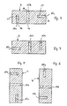
- the device for washing workpieces shown schematically in section in FIG. 1, consists of an outer container 1 and a basket 2 suspended in it, which has walls formed as a sieve.
- the outer container 1 and the basket 2 form a washing container.
- the washing container 1, 2 is filled with a washing liquid 20 which is fed to the bottom 19 of the outer container 1 via an inlet by means of a circulation pump 12 and is returned to the pump via an outlet 11 in the upper region of the outer container 1.
- the drain 11 is arranged in the area of an overflow 8 on the basket 2 of the washing container.
- a separator is in the form of the overflow 8 a sieve 9 is provided in order not to let rinsed foreign bodies into the outlet 11, and thus into the circuit of the washing water.
- a gear head 5 is suspended on the outer container 1 by means of a cross member 22 and by means of a holder 21, which (in the present case) has two gripping devices 3 for holding a workpiece 4 each.
- the gear head 5 is designed such that it exerts a wobbling movement on the workpieces 4, i.e. a multidimensional movement about several axes, of which the horizontal axis 6 and the vertical axis 7 are indicated in FIG. 1. It is important for such a wobble movement or other movement about several axes that each of the workpieces 4 executes such a movement in the washing container that each surface or opening of the workpieces successively one after the other essentially downwards and once essentially upwards shows.
- An air line 13 is introduced into the inlet 10 for the washing liquid and compressed air is supplied via a blower 14.
- This injected compressed air rises in the form of air bubbles in the washing liquid, that is, it passes through the bottom of the basket 2 into the area of the workpieces 4. Since the air or another gas is larger with respect to solids, such as the foreign bodies to be removed Affinity as compared to the washing liquid 20, the air bubbles adhere to the foreign bodies and tear them up due to the buoyancy. They also climb into downward openings in bores and channels or the like in the workpieces.
- Fig. 2 shows another embodiment of the device according to the invention in partial view.
- a plurality of nozzles is arranged, to which compressed air is fed from the blower 14 via the air line 13.
- compressed air is fed from the blower 14 via the air line 13.
- a workpiece 4 is now shown in different positions in order to explain the effect of the method according to the invention.
- the workpiece 4 has a multiplicity of bores, channels or other depressions 15a, 15b and 15c which are connected to the outer surfaces of the workpiece via openings 16.
- In these holes or the like 15 there are schematically indicated foreign substances 17 such as chips from a previous machining production process.
- the blind bore 15a is now open at the top, so that the air bubbles with the foreign bodies bound to them can escape upwards through buoyancy.
- the through hole 15b is concerned, any foreign bodies still hanging on the unevenness of the walls have the opportunity to rise from the through hole in the opposite direction. Practically nothing has changed with regard to the blind bore 15c lying on the side.
- the air bubbles can move into the position shown in FIG. 3 and 4 ascend lateral blind hole 15c, bind foreign bodies and collect in the upper end of blind hole 15c.
- the air bubbles with the foreign bodies can leave the blind bore 15c which is now pointing upwards.
- each hole, in particular blind hole or each channel is positioned one after the other in such a way that air bubbles can get in and then get out again by buoyancy.
- the affinity of the air bubbles for the foreign bodies, in particular metal chips, is so great that the bores, cavities or the like. of the workpieces 4 in a relatively short time, i.e. after a few revolutions of the gear head, are rinsed free, so that the workpieces can be used without further manual cleaning.
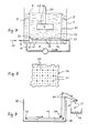
- FIGS. 7 and 8 The further device according to the invention shown in FIGS. 7 and 8 has the following differences compared to the embodiments described above:
- An inner container 30 with an overflow 8 is arranged in a closed outer container 1. Via an inlet 10, washing liquid 20 is pumped in via pump nozzles 31 in the direction of the arrow by means of a pump 12, and the washing liquid overflowing via the overflow 8 is pumped out again via an outlet 11.
- the foreign bodies 17 overflowing with the overflow 8 are collected in a sieve 9 and removed from there in a suitable manner.
- Compressed air 39 is supplied via an air line 13 and passes via air nozzles 33 between the water nozzles 31 into the lower part of the inner container 30.
- the water nozzles 31 and the air nozzles 33 are arranged in the lower part of the inner container 30 in the following way: In the lower region of the inner container 30, an intermediate base 34 is drawn in, which creates an intermediate space 32 between itself and the base 19 of the inner container. A large number of water nozzles 31 are arranged in the intermediate floor 34 (see in particular FIG. 8) at regular intervals, and air nozzles 33, which are designed as fine bores in the intermediate floor 34, are provided evenly between them in a finer grid.
- the water nozzles 31 are structurally in the form of nozzle tubes arranged in the intermediate floor 34, which are connected to the inlet 10.
- the air nozzles 33 in the form of fine bores are supplied with compressed air from the air line 13 via the intermediate space 32.
- the uniform and alternating arrangement of the water nozzles 31 and the air nozzles 33 results in a relatively uniform water flow with finely distributed air bubbles in the inner container 30 from bottom to top, with hardly any swirling. This uniform water-air flow sweeps past the workpiece 4 and tears up foreign matter such as chips from its surface.
- the workpiece 4 is shown in Fig. 7 only schematically hanging on a bracket 21. If there are workpieces that do not have blind holes, it is not necessary to give the workpiece 4 a movement rotating about a horizontal axis (as in the exemplary embodiments described above), but the uniform ascending water-air flow is sufficient, to achieve a sufficient cleaning effect. However, if the workpiece 4 has blind holes or other inaccessible channels, the workpiece is expediently rotated about a horizontal axis, or it is allowed to perform a wobbling movement.
- a further improvement in the cleaning effect can be achieved in that (see FIG. 7) a vibration generator 46 is provided, which acts on the workpiece 4 immersed in the washing liquid 20.
- This vibration generator 46 can either be coupled directly to the workpiece or is arranged at a suitable location in the washing container.
- FIG. 9 is particularly suitable for removing steel and iron chips from the washing container. While, for example, aluminum chips are almost entirely removed via the overflow 8 by the rising water-air mixture, it can also be the case with steel or iron chips come that they fall to the bottom of the washing container 40 and must be removed from there from time to time.
- a magnetic conveyor belt 42 is provided in the floor area, which is guided over suitably arranged deflection rollers 41 and driven in a corresponding manner.
- the foreign bodies present on the magnetic conveyor belt 42 are attracted to the magnetic conveyor belt 42 and are guided outwards over the edge of the washing container.
- a wiping lip 45 wipes off the foreign bodies 17 so that they fall into a collecting container 44.
- corresponding water nozzles 31 and air nozzles 33 are of course provided above the magnetic conveyor belt 42, as in the exemplary embodiments described above, or corresponding similar parts are arranged according to the embodiments according to FIGS. 1 and 2.
- these parts must be permeable to the falling foreign bodies 17, which in the case of the water nozzles 31 and air nozzles 33 shown in FIG. 7 can be designed in such a way that the air nozzles 33 are also designed in the form of interconnected air tubes with nozzles.
Abstract
Description
Die Erfindung betrifft ein Verfahren zum Reinigen von Werkstücken von Fremdkörpern wie Spänen o.dgl. durch Waschen mit einer Waschflüssigkeit in einem Waschbehälter unter Einblasen von Druckluft o.dgl. unterhalb der Werkstücke, sowie eine Vorrichtung zur Durchführung des Verfahrens.The invention relates to a method for cleaning workpieces from foreign bodies such as chips or the like. by washing with a washing liquid in a washing container while blowing in compressed air or the like. below the workpieces, as well as a device for performing the method.
In der metallverarbeitenden Industrie, insbesondere in der spanabhebenden Bearbeitung von Spritzgußteilen durch Bohren, Fräsen und Drehen verbleiben an den bearbeiteten Werkstücken Metallspäne, die vor einer Weiterverarbeitung der Werkstücke entfernt werden müssen, was in der Regel durch Waschen der Werkstücke in einem Waschbehälter geschieht. Die Waschflüssigkeit besteht meist aus Wasser mit Reinigungszusätzen, und die Waschflüssigkeit in dem Waschbehälter wird, um an alle Flächen, Vertiefungen, Bohrungen usw. der Werkstücke heranzukommen, durch Pumpen o.dgl. in Bewegung gehalten. Insbesondere bei der Bearbeitung von Teilen aus Aluminium oder Aluminiumlegierungen lassen sich Fremdkörper wie Späne nur sehr schwer aus verwinkelten Bohrungen und Sacklöchern entfernen, so daß meist eine manuelle Nachreinigung mittels geeigneter Bürsten oder Reinigungsspritzen sowie mittels Preßluft angewandt wird. Eine solche manuelle Nachreinigung ist jedoch mit hohem Aufwand verbunden und gibt dennoch keine ausreichende Sicherheit, daß die bearbeiteten Teile frei von Spänen und anderen Fremdkörpern sind, was sich besonders bei im Betrieb später aufeinander gleitenden oder bewegenden Teilen außerordentlich nachteilig auswirken kann. Als Beispiele solcher, schwierig zu reinigender Werkstücke sind Motorblöcke, Zylinderköpfe, Ölpumpen- und Wasserpumpengehäuse, Ansaugkrümmer und sonstige Teile aus der Automobilindustrie zu nennen, die aufgrund ihrer komplizierten Form mit einer Vielzahl von gewundenen Kanälen, Kammern, Durchgangs- und Sackbohrungen besonders schwierig zu reinigen sind, was sich insbesondere bei der Serienfertigung sehr nachteilig auswirkt.In the metalworking industry, especially in the machining of injection molded parts drilling, milling and turning leave metal chips on the machined workpieces, which have to be removed before further processing of the workpieces, which is usually done by washing the workpieces in a washing container. The washing liquid usually consists of water with cleaning additives, and the washing liquid in the washing container is pumped or the like to get to all surfaces, recesses, bores, etc. of the workpieces. kept moving. Especially when machining parts made of aluminum or aluminum alloys, foreign bodies such as chips can only be removed from angled bores and blind holes with great difficulty, so that manual subsequent cleaning using suitable brushes or cleaning syringes and using compressed air is usually used. Such manual post-cleaning is, however, associated with great effort and nevertheless does not provide sufficient certainty that the machined parts are free of chips and other foreign bodies, which can have an extremely disadvantageous effect, in particular when parts slide or move later in operation. Examples of such difficult-to-clean workpieces include engine blocks, cylinder heads, oil pump and water pump housings, intake manifolds and other parts from the automotive industry, which are particularly difficult to clean due to their complicated shape with a large number of tortuous channels, chambers, through and blind holes are, which has a particularly disadvantageous effect in series production.
Aus dem DE-GM 84 37 870 ist es bereits bekannt, in einem mit einer Waschflüssigkeit gefüllten Wasch behälter zusätzlich von der Seite her über in der Höhe gestaffelte Düsen Waschflüssigkeit mit hohem Druck einzuspritzen und das Werkstück dabei um eine etwa waagerechte Achse zu drehen bzw. eine Taumelbewegung ausführen zu lassen. Auf diese Weise sollen alle Seiten des Werkstückes von den Düsenstrahlen erreicht werden. Diese bekannte Vorrichtung arbeitet nach dem sogenannten Kavitationsverfahren, bei dem das unter hohem Druck eingespritzte Wasser Dampfblasen bildet, die beim Auftreffen auf das Werkstück implodieren und hierbei Fremdkörper wie Späne von dem Werkstück mitreißen und lösen sollen. Dieses bekannte Verfahren erfordert jedoch sehr hohe Pumpleistungen, und die Entfernung von Spänen aus sehr schwer zugänglichen Bohrungen und Kanälen ist meist unbefriedigend.From DE-GM 84 37 870 it is already known in a wash filled with a washing liquid inject the washing liquid at high pressure from the side using staggered nozzles and rotate the workpiece around an approximately horizontal axis or let it tumble. In this way, all sides of the workpiece should be reached by the nozzle jets. This known device works according to the so-called cavitation process, in which the water injected under high pressure forms vapor bubbles which implode when it hits the workpiece and are intended to entrain and loosen foreign bodies such as chips from the workpiece. However, this known method requires very high pumping capacities, and the removal of chips from bores and channels that are very difficult to access is usually unsatisfactory.
Aus der FR-A 23 78 577 ist ein Verfahren zum Waschen von Obst oder Gemüse bekannt, bei dem in einen Waschbehälter mit Waschflüssigkeit von unten und von der Seite her Luft eingeblasen wird, um durch entsprechend starke Verwirbelung auch sonst unzugängliche Flächen des Obstes bzw. des Gemüses mit Waschflüssigkeit zu erreichen. Dieses bekannte Verfahren hat jedoch zur Folge, daß die während der Verwirbelung der Waschflüssigkeit gelösten Fremdstoffe sich an anderen Stellen wieder niederschlagen, insbesondere, weil auch nach einigen Reinigungszyklen das Waschwasser immer stärker verschmutzt.From FR-A 23 78 577 a method for washing fruit or vegetables is known, in which air is blown into a washing container with washing liquid from below and from the side in order to also make otherwise inaccessible areas of the fruit or to reach the vegetables with washing liquid. However, this known method has the consequence that the foreign substances dissolved during the swirling of the washing liquid are deposited again in other places, in particular because the washing water becomes increasingly dirty even after a few cleaning cycles.
Der vorliegenden Erfindung liegt die Aufgabe zugrunde, ein Verfahren sowie eine Vorrichtung zum Reinigen von Werkstücken von Fremdkörpern wie Spänen o.dgl. vorzu schlagen, das bzw. die auch bei komplizierten Formen der Werkstücke eine einwandfreie, weitgehend automatische Reinigung ohne die Notwendigkeit einer manuellen Nachreinigung zuläßt.The present invention has for its object a method and an apparatus for cleaning workpieces from foreign bodies such as chips or the like. preferred suggest that, even with complicated shapes of the workpieces, allows a flawless, largely automatic cleaning without the need for manual subsequent cleaning.
Diese Aufgabe wird erfindungsgemäß durch ein Verfahren der eingangs genannten Art gelest, das dadurch gekennzeichnet ist, daß über einen im unteren Bereich des Waschbehälters angeordneten Zulauf Waschflüssigkeit eingepumpt und über einen Überlauf des Waschbehälters abgepumpt wird, und daß im Bereich des Zulaufs die Druckluft o.dgl. eingeführt wird.This object is achieved according to the invention by a method of the type mentioned at the outset, which is characterized in that washing liquid is pumped in via an inlet arranged in the lower region of the washing container and pumped out via an overflow of the washing container, and that in the region of the inlet the compressed air or the like . is introduced.
Die Erfindung wertet die Eigenschaft von Luft oder anderen Gasen aus, eine größere Affinität in Bezug auf Feststoffe als in Bezug auf Wasser oder Flüssigkeiten aufzuweisen, d. h. also, daß die Luft (oder das Gas) die Eigenschaft hat, sich beim Einblasen in die Waschflüssigkeit an die Fremdkörper in den Bohrungen, Vertiefungen u.dgl. der Werkstücke zu binden und aufgrund der Auftriebskräfte in der Waschflüssigkeit nach oben zu steigen. Der vorstehend beschriebene Erfindungsgedanke führt schon zu einer außerordentlich guten Reinigung der Werkstücke. Das allgemeine Prinzip der Anwendung von aufsteigender Luft im Waschwasser läßt sich bei besonders unzugänglichen und verzweigten Kanälen in den Werkstücken besonders dann vorteilhaft anwenden, wenn gemäß einem weiteren Merkmal der Erfindung die Werkstücke in dem Waschbehälter um eine etwa waagerechte Achse derart bewegt werden, daß in den Werkstücken vorhandene Bohrungen, Kanäle oder sonstige Vertiefungen gegenüber der Waagerechten mit ihren Öffnungen nacheinander nach unten bzw. nach oben gerichtet sind und die unterhalb der Werkstücke eingeblasene Luft o.dgl. in die im Verlaufe der Drehung der Werkstücke nach unten gerichteten Bohrungen, Kanäle oder sonstigen Vertiefungen der Werkstücke eindringt und aus diesen danach im Verlaufe des Weiterdrehens nach oben unter Mitreißen der Späne o.dgl. wieder herausströmt. Dieses Prinzip ist sowohl bei einem Reinigungsverfahren mit über einen Überlauf umgewälzten Waschmittelkreislauf als auch ohne einen solchen anwendbar.The invention evaluates the property of air or other gases to have a greater affinity for solids than for water or liquids, ie that the air (or gas) has the property of blowing into the wash liquid the foreign bodies in the bores, depressions and the like. bind the workpieces and rise due to the buoyancy forces in the washing liquid. The inventive concept described above already leads to an extremely good cleaning of the workpieces. The general principle of the use of rising air in the wash water can be used particularly advantageously in the case of particularly inaccessible and branched channels in the workpieces if, according to a further feature of the invention, the workpieces are moved in the wash tank about an approximately horizontal axis in such a way that in the Workpieces existing bores, channels or other recesses compared to the horizontal with their Openings are directed downwards or upwards in succession and the air or the like blown in below the workpieces. penetrates into the bores, channels or other depressions of the workpieces directed downward in the course of the rotation of the workpieces and thereafter or the like in the course of the further rotation while entraining the chips. flows out again. This principle can be used both in a cleaning process with a detergent circuit circulated via an overflow and without one.
Durch Bewegung der Werkstücke um zumindest die waagerechte Achse sind Höhlungen und Kammern wie z.B. Sacklöcher in den Werkstücken mit ihrer Öffnung zu einem bestimmten Zeitpunkt nach unten gerichtet, so daß die eingeblasene Luft in die Sackbohrungen aufsteigt, sich an die Fremdkörper bindet und beim weiteren Rotieren des Werkstückes um z. B. 180° aus der dann nach oben gerichteten Öffnung aus dem Sackloch durch Auftrieb heraussteigt. Durch diese Kombination von Maßnahmen wird eine außerordentlich hohe Reinigungswirkung erzielt; diese Wirkung ist selbstverständlich auch bei durchgehenden Bohrungen und Kanälen gegeben.By moving the workpieces around at least the horizontal axis, cavities and chambers such as e.g. Blind holes in the workpieces with their opening directed downwards at a certain point in time, so that the blown-in air rises into the blind holes, binds to the foreign bodies and, when the workpiece continues to rotate, z. B. 180 ° out of the then upward opening from the blind hole by buoyancy. This combination of measures achieves an extraordinarily high cleaning effect; this effect is of course also given with through holes and channels.
Die Erfindung betrifft auch eine Vorrichtung zur Durchführung des erfindungsgemäßen Verfahrens. Eine solche ist gekennzeichnet durch einen in dem Waschbehälter angeordneten Getriebekopf, an dem die Werkstücke befestigbar sind und der zur Erzeugung einer Bewegung der Werkstücke mindestens um eine etwa waagerechte Achse, insbesondere in Form einer Taumel bewegung, ausgebildet ist. Der Getriebekopf weist vorzugsweise mindestens eine Greifeinrichtung zum lösbaren Halten eines Werkstückes auf. Durch eine solche Greifeinrichtung können die Werkstücke in einer Serienfertigung manuell oder automatisch ergriffen, in den Waschbehälter eingetaucht und in diesem in der angegebenen Weise bewegt werden.The invention also relates to a device for carrying out the method according to the invention. Such is characterized by a gear head arranged in the washing container, to which the workpieces can be fastened and which for generating movement of the workpieces at least about an approximately horizontal axis, in particular in the form of a wobble movement, is formed. The gear head preferably has at least one gripping device for releasably holding a workpiece. By means of such a gripping device, the workpieces can be gripped manually or automatically in series production, immersed in the washing container and moved in the manner indicated.
Die Bewegung des Werkstückes bzw. der Werkstücke muß zumindest um eine etwa waagerechte Achse erfolgen, damit Bohrungen und Kammern mit nur einer Zugangsöffnung zum Einsteigen der eingeblasenen Luft nach unten und zum Herauslassen der Luft mit daran gebundenen Fremdkörpern durch Auftrieb nach oben gerichtet ist.The movement of the workpiece or workpieces must take place at least about an approximately horizontal axis, so that bores and chambers with only one access opening for entry of the blown-in air downwards and for discharging the air with foreign bodies bound to them are directed upwards by buoyancy.
Eine besonders vorteilhafte Ausführungsform der Erfindung ist dadurch gekennzeichnet, daß an einem Überlauf des Waschbehälters vorzugsweise eine Abscheideeinrichtung, insbesondere ein Sieb, vorgesehen ist, um die Fremdkörper aus dem Kreislauf der Waschflüssigkeit laufend zu entfernen.A particularly advantageous embodiment of the invention is characterized in that a separating device, in particular a sieve, is preferably provided on an overflow of the washing container in order to continuously remove the foreign bodies from the circuit of the washing liquid.
Für den Fall, daß der Zulauf der Waschflüssigkeit des Waschbehälters unterhalb der Werkstücke angeordnet ist, kann die eingeblasene Luft zweckmäßigerweise in den Zulauf injiziert werden. Es ist jedoch auch möglich, am Boden des Waschbehälters eine Mehrzahl von Düsen anzuordnen, in die die Druckluft eingeblasen wird.In the event that the inlet of the washing liquid of the washing container is arranged below the workpieces, the air blown in can expediently be injected into the inlet. However, it is also possible to arrange a plurality of nozzles into the bottom of the washing container, into which the compressed air is blown.
Eine besonders vorteilhafte Ausführungsform der erfindungsgemäßen Vorrichtung, bei der eine Bewegung des Werkstückes um eine mindestens waagerechte Achse in den meisten Fällen nicht erforderlich ist, ist dadurch gekennzeichnet, daß der Zulauf am Boden des Waschbehälters in der Form von mehreren Wasserdüsen ausgebildet ist, und daß über zwischen den Wasserdüsen angeordnete Luftdüsen die Druckluft oder ein anderes Gas eingeführt wird, derart, daß sich ein gleichmäßiger Wasserstrom mit fein verteilten Luftbläschen im wesentlichen ohne Verwirbelung von unten nach oben an den im Waschbehälter angeordneten Werkstücken vorbei ergibt. Bei besonders kritischen Werkstücken mit weit verzweichten Bohrungen, insbesondere bei Sackbohren, wird man jedoch ein Bewegen des Werkstückes um mindestens die waagerechte Achse vorsehen.A particularly advantageous embodiment of the device according to the invention, in which a movement of the workpiece about an at least horizontal axis in In most cases, this is not necessary, characterized in that the inlet at the bottom of the washing container is in the form of a plurality of water nozzles, and that compressed air or another gas is introduced via air nozzles arranged between the water nozzles, in such a way that an even one Water flow with finely divided air bubbles results essentially without swirling from bottom to top past the workpieces arranged in the washing container. In the case of particularly critical workpieces with widely branched bores, in particular with pocket drilling, however, the workpiece will be moved around at least the horizontal axis.
Eine besonders einfache Konstruktion dieser Ausführungsform ist dadurch gekennzeichnet, daß der Waschbehälter einen Zwischenboden aufweist, in dem die Wasserdüsen in gleichmäßigen Abständen angeordnet sind und in dem zwischen den Wasserdüsen in gleichmäßigen, feineren Abständen Luftbohrungen vorgesehen sind, und daß der Zwischenraum unter dem Zwischenboden an eine Druckluftquelle anschließbar ist.A particularly simple construction of this embodiment is characterized in that the washing container has an intermediate floor, in which the water nozzles are arranged at regular intervals and in which air holes are provided between the water nozzles at uniform, finer intervals, and in that the intermediate space under the intermediate floor connects to one Compressed air source can be connected.
Während das erfindungsgemäße Verfahren und die erfindungsgemäße Vorrichtung bei dem Entfernen von verhältnismäßig leichten Fremdkörpern wie Spänen diese entfernten Fremdkörper ohne Probleme über den Überlauf des Waschbehälters spülen kann, kann es bei durch die Bearbeitung von Stahlteilen oder Stahlguß anfallenden Spänen wegen des größeren Gewichtes dazu führen, daß diese auf den Boden des Waschbehälters fallen, so daß sie von Zeit zu Zeit entfernt werden müssen. Um die hierdurch bedingten Betriebsunterbrechungen zu vermeiden, ist eine weitere vorteilhafte Ausführungsform dadurch gekennzeichnet, daß am Boden des Waschbehälters ein Magnetabscheider in der Form eines Magnet-Förderbandes vorgesehen ist, durch das die magnetisch angezogenen Fremdkörper nach außen befördert werden.While the method and the device according to the invention can rinse these removed foreign bodies without problems over the overflow of the washing container when removing relatively light foreign bodies such as chips, it can lead to chips due to the machining of steel parts or cast steel because of the greater weight these fall to the bottom of the washing container so that they have to be removed from time to time. To the to avoid operational interruptions caused thereby, a further advantageous embodiment is characterized in that a magnetic separator in the form of a magnetic conveyor belt is provided at the bottom of the washing container, through which the magnetically attracted foreign bodies are conveyed to the outside.
Zur weiteren Verbesserung der Reinigungswirkung ist es auch möglich, auf das in den Waschbehälter eingetauchte Werkstück einen Schwingungserzeuger einwirken zu lassen, der entweder das Werkstück selbst oder die Waschflüssigkeit in Schwingungen versetzt.To further improve the cleaning effect, it is also possible to have a vibration generator act on the workpiece immersed in the washing container, which generator either vibrates the workpiece itself or the washing liquid.
Um ein leichtes Entfernen von zu Boden fallenden Spänen oder sonstigen Fremdkörpern im Waschbehälter zu ermöglichen, besteht dieser gemäß einer vorteilhaften Ausführungsform aus einem Außenbehälter und einem darin eingehängten Korb mit als Sieb ausgebildeten Wandungen. Dieser Korb kann in größeren Abständen nach Wegbewegen des Getriebekopfes aus dem Außenbehälter entfernt und gereinigt werden, um ein Zustopfen oder Wiederaufwirbeln mit Fremdkörpern zu vermeiden.In order to make it easy to remove chips or other foreign bodies falling to the floor in the washing container, according to an advantageous embodiment, this consists of an outer container and a basket suspended therein with walls designed as a sieve. This basket can be removed and cleaned at greater intervals after moving the gear head away from the outer container in order to avoid plugging or swirling with foreign bodies.
Die Erfindung wird nachfolgend anhand von Ausführungsbeispielen unter Bezug auf die beigefügten Zeichnungen näher erläutert.The invention is explained in more detail below on the basis of exemplary embodiments with reference to the accompanying drawings.
Es zeigen:
- Fig. 1 eine schematische Schnittdarstellung einer Vorrichtung zur Durchführung des erfindungsgemäßen Verfahrens;
- Fig. 2 eine Teilansicht des Waschbehälters in abgewandelter Form;
- Fig. 3 bis 6 schematische Darstellungen eines Werkstückes im Schnitt in verschiedenen Stellungen während des Bewegungsablaufes;
- Fig. 7 eine schematische Schnittdarstellung einer weiteren Vorrichtung zur Durchführung des erfindungsgemäßen Verfahrens;
- Fig. 8 eine Draufsicht auf einen Ausschnitt auf einen Zwischenboden der Vorrichtung nach Fig. 7; und
- Fig. 9 eine schematische Seitendarstellung im Schnitt durch eine weitere Vorrichtung gemäß der vorliegenden Erfindung.
- Figure 1 is a schematic sectional view of an apparatus for performing the method according to the invention.
- Figure 2 is a partial view of the washing container in a modified form.
- 3 to 6 are schematic representations of a workpiece in section in different positions during the movement sequence;
- 7 shows a schematic sectional illustration of a further device for carrying out the method according to the invention;
- FIG. 8 shows a plan view of a section of an intermediate floor of the device according to FIG. 7; and
- Fig. 9 is a schematic side view in section through a further device according to the present invention.
Die in Fig. 1 schematisch im Schnitt gezeigte Vorrichtung zum Waschen von Werkstücken besteht aus einem Außenbehälter 1 und einem in diesen eingehängten Korb 2, der als Sieb ausgebildete Wandungen aufweist. Der Außenbehälter 1 und der Korb 2 bilden einen Waschbehälter. Der Waschbehälter 1, 2 ist mit einer Waschflüssigkeit 20 gefüllt, die am Boden 19 des Außenbehälters 1 über einen Zulauf mittels einer Umwälzpumpe 12 zugeleitet und über einen Ablauf 11 im oberen Bereich des Außenbehälters 1 zur Pumpe zurückgeführt wird. Der Ablauf 11 ist im Bereich eines Überlaufs 8 am Korb 2 des Waschbehälters angeordnet. Im Bereich des Überlaufes 8 ist eine Abscheideeinrichtung in Form eines Siebes 9 vorgesehen, um ausgespülte Fremdkörper nicht in den Ablauf 11, und damit in den Kreislauf des Waschwassers, zu lassen.The device for washing workpieces, shown schematically in section in FIG. 1, consists of an outer container 1 and a
Am Außenbehälter 1 ist mittels eines Querträgers 22 und mittels einer Halterung 21 ein Getriebekopf 5 eingehängt, der (im vorliegenden Fall) zwei Greifeinrichtungen 3 zum Haltern je eines Werkstückes 4 aufweist. Der Getriebekopf 5 ist derart ausgebildet, daß er auf die Werkstücke 4 eine taumelnde Bewegung ausübt, d.h. eine mehrdimensionale Bewegung um mehrere Achsen, von denen in Fig. 1 die waagerechte Achse 6 und die senkrechte Achse 7 angedeutet sind. Wichtig für eine solche Taumelbewegung oder auch andere Bewegung um mehrere Achsen ist, daß jedes der Werkstücke 4 in dem Waschbehälter eine derartige Bewegung ausführt, daß jede Fläche bzw. Öffnung der Werkstücke im zeitlichen Ablauf nacheinander einmal im wesentlichen nach unten und einmal im wesentlichen nach oben zeigt.A gear head 5 is suspended on the outer container 1 by means of a
In den Zulauf 10 für die Waschflüssigkeit ist eine Luftleitung 13 eingeführt, der über ein Gebläse 14 Preßluft zugeführt wird. Diese eingeblasene Preßluft steigt in Form von Luftblasen in der Waschflüssigkeit nach oben, d.h., sie gelangt durch den Boden des Korbes 2 in den Bereich der Werkstücke 4. Da die Luft bzw. ein anderes Gas bezüglich Festkörpern, wie den zu entfernenden Fremdkörpern, eine größere Affinität hat als gegeniber der Waschflüssigkeit 20, haften die Luftblasen den Fremdkörpern und reißen diese aufgrund des Auftriebes nach oben. Sie steigen hierbei auch in nach unten gerichtete Öffnungen von Bohrungen, Kanälen o.dgl. in den Werkstücken auf. Werden die Werkstücke 4 durch den Getriebekopf 5 nun weiter bewegt in der Weise, daß die vorher nach unten zeigende Öffnung nach oben gerichtet ist, so steigen die Luftbläschen mit den daran haftenden Fremdkörpern durch Auftrieb nach oben und werden auf diese Weise aus den Bohrungen o.dgl. herausgerissen und gelangen an die Oberfläche der Waschflüssigkeit 20. Da die Zirkulation der Waschflüssigkeit 20 derart erfolgt, daß im Bereich des Überlaufes 8 über den Ablauf 11 abgesaugt wird, werden die hochgespülten Fremdkörper aus dem Waschbehälter entfernt, d.h., sie werden an dem Sieb 9 zurückgehalten, wo sie gelegentlich entfernt werden können.An
Fig. 2 zeigt eine andere Ausführungsform der erfindungsgemäßen Vorrichtung in Teilansicht. Im Boden 19 des Außenbehälters 1 ist eine Vielzahl von Düsen angeordnet, denen über die Luftleitung 13 Preßluft von dem Gebläse 14 zugeleitet wird. Durch diese Ausbildung werden über eine größere Fläche im Waschbehälter aufsteigende Luftblasen erzeugt, die in die nach unten gerichteten Bohrungen, Kanäle o.dgl. der Werkstücke 4 hineingelangen können.Fig. 2 shows another embodiment of the device according to the invention in partial view. In the bottom 19 of the outer container 1, a plurality of nozzles is arranged, to which compressed air is fed from the
In den Fig. 3 bis 6 ist nun ein Werkstück 4 in verschiedenen Positionen gezeigt, um die Wirkung des erfindungsgemäßen Verfahrens zu erläutern. Das Werkstück 4 weist eine Vielzahl von Bohrungen, Kanälen oder sonstigen Vertiefungen 15a, 15b und 15c auf, die mit den Außenflächen des Werkstückes über Öffnungen 16 in Verbindung stehen. In diesen Bohrungen o. dgl. 15 befinden sich schematisch angedeutete Fremdstoffe 17 wie Späne aus einem vorhergehenden, spanabhebenden Fertigungsvorgang.3 to 6, a
Bei der in Fig. 3 gezeigten Position können von unten aufsteigende Luftblasen (s. Beschreibung der Fig. 1) in das Sacklock 15a über die Öffnung 16 hineingelangen und die Fremdkörper 17 binden. Luftbläschen mit Fremdkörpern 17 sammeln sich dann im oberen Bereich des Sackloches 15a. Desgleichen können Luftbläschen über die Öffnung 16 der Durchgangsbohrung 15b aufsteigen, sich mit den Fremdkörpern verbinden und sogleich diese Durchgangsbohrung über die obere Öffnung 16 verlassen. Ein Aufsteigen von Bläschen in die seitlich liegende Sackbohrung 15c wird nur in unvollkommener Weise erfolgen; es sei denn, diese Bohrung wäre leicht nach unten geneigt.In the position shown in FIG. 3, air bubbles rising from below (see description of FIG. 1) can enter the
Wird das Werkstück 4 nun in die in Fig. 4 dargestellt Position gedreht, was einer Rotation um 180° entspricht, so ist die Sackbohrung 15a nunmehr nach oben hin offen, so daß die Luftbläschen mit den daran gebundenen Fremdkörpern durch Auftrieb nach oben entweichen können. Soweit es um die Durchgangsbohrung 15b geht, haben etwaige, noch an Unebenheiten der Wandungen noch hängende Fremdkörper die Gelegenheit, in entgegengesetzter Richtung aus der Durchgangsbohrung aufzusteigen. Bezüglich der seitlich liegenden Sackbohrung 15c hat sich praktisch nichts geändert.If the
Gelangt das Werkstück nun in die in Fig. 5 dargestellte Position, so können die Luftbläschen in die in den Fig. 3 und 4 seitlich liegende Sackbohrung 15c aufsteigen, Fremdkörper binden und sich im oberen Ende der Sackbohrung 15c sammeln. Beim Weiterbewegen des Werkstückes in die Position nach Fig. 6 können die Luftbläschen mit den Fremdkörpern die jetzt nach oben zeigende Sackbohrung 15c verlassen.If the workpiece now reaches the position shown in FIG. 5, the air bubbles can move into the position shown in FIG. 3 and 4 ascend lateral
Die vorstehenden Ausführungen zeigen also, daß durch entsprechendes Bewegen des Werkstückes 4 um mehrere Achsen, insbesondere jedoch um eine waagerechte Achse, jede Bohrung, insbesondere Sackbohrung oder jeder Kanal zeitlich nacheinander derart positioniert ist, daß Luftbläschen hineingelangen und anschließend durch Auftrieb wieder herausgelangen können. Die Affinität der Luftbläschen gegenüber den Fremdkörpern, insbesondere Metallspänen, ist derart groß, daß die Bohrungen, Höhlungen o.dgl. der Werkstücke 4 in verhältnismäßig kurzer Zeit, d.h. nach wenigen Umdrehungen des Getriebekopfes, freigespült sind, so daß die Werkstücke ohne manuelle Nachreinigung der weiteren Verwendung zugeführt werden können.The above explanations therefore show that by appropriately moving the
Die in den Fig. 7 und 8 dargestellte weitere Vorrichtung gemäß der Erfindung weist gegenüber den vorstehend beschriebenen Ausführungsformen folgende Unterschiede auf:The further device according to the invention shown in FIGS. 7 and 8 has the following differences compared to the embodiments described above:
In einem geschlossenen Außenbehälter 1 ist ein Innenbehälter 30 mit Überlauf 8 angeordnet. Über einen Zulauf 10 wird in Pfeilrichtung mittels einer Pumpe 12 Waschflüssigkeit 20 über Wasserdüsen 31 eingepumpt, und die über den Überlauf 8 überfließende Waschflüssigkeit wird über einen Ablauf 11 wieder abgepumpt. Die über den Überlauf 8 mit überfließenden Fremdkörper 17 werden in einem Sieb 9 aufgefangen und von dort auf geeignete Weise entfernt. Über eine Luftleitung 13 wird Preßluft 39 zugeführt und gelangt über Luftdüsen 33 zwischen den Wasserdüsen 31 in den unteren Teil des Innenbehälters 30.An
Die Wasserdüsen 31 und die Luftdüsen 33 sind im unteren Teil des Innenbehälters 30 auf folgende Weise angeordnet: Im unteren Bereich des Innenbehälters 30 ist ein Zwischenboden 34 eingezogen, der zwischen sich und dem Boden 19 des Innenbehälters einen Zwischenraum 32 schafft. In dem Zwischenboden 34 sind (siehe insbesondere Fig. 8) in gleichmäßigen Abständen eine Vielzahl von Wasserdüsen 31 angeordnet, und gleichmäßig zwischen diesen sind in feinerem Raster Luftdüsen 33 vorgesehen, die als feine Bohrungen in dem Zwischenboden 34 ausgebildet sind. Die Wasserdüsen 31 haben konstruktiv die Form von in den Zwischenboden 34 angeordneten Düsenrohren, die zusammengefaßt an den Zulauf 10 angeschlossen sind.The water nozzles 31 and the
Die Luftdüsen 33 in der Form von feinen Bohrungen werden über den Zwischenraum 32 von der Luftleitung 13 mit Preßluft versorgt.The air nozzles 33 in the form of fine bores are supplied with compressed air from the
Durch die gleichmäßige und abwechselnde Anordnung der Wasserdüsen 31 und der Luftdüsen 33 ergibt sich ein verhältnismäßig gleichmäßiger Wasserstrom mit fein verteilten Luftbläschen im Innenbehälter 30 von unten nach oben, wobei es kaum zu Verwirbelungen kommt. Dieser gleichmäßige Wasser-Luft-Strom streicht an dem Werkstück 4 vorbei und reißt von dessen Oberfläche Fremdkörper wie Späne mit nach oben.The uniform and alternating arrangement of the
Das Werkstück 4 ist in Fig. 7 nur schematisch an einer Halterung 21 hängend dargestellt. Handelt es sich um Werkstücke, die keine Sackbohrungen aufweisen, so ist es nicht erforderlich, dem Werkstück 4 eine um eine waagerechte Achse drehende Bewegung zu geben (wie in den vorstehend beschriebenen Ausführungsbeispielen), sondern der gleichmäßige aufsteigende Wasser-Luft-Strom reicht aus, eine ausreichende Reinigungswirkung zu erzielen. Weist das Werkstück 4 jedoch Sackbohrungen oder sonstige unzugängliche Kanäle auf, so wird das Werkstück zweckmäßigerweise um eine waagerechte Achse gedreht, oder man läßt es eine taumelnde Bewegung ausführen.The
Eine weitere Verbesserung der Reinigungswirkung kann dadurch erzielt werden, daß (siehe Fig. 7) ein Schwingungserzeuger 46 vorgesehen ist, der auf das in die Waschflüssigkeit 20 eingetauchte Werkstück 4 einwirkt. Dieser Schwingungserzeuger 46 kann entweder direkt mit dem Werkstück gekoppelt werden oder ist an geeigneter Stelle im Waschbehälter angeordnet.A further improvement in the cleaning effect can be achieved in that (see FIG. 7) a
In Fig. 9 ist nun eine weitere Ausführungsform gezeigt, die insbesondere zur Entfernung von Stahl- und Eisenspänen aus dem Waschbehälter geeignet ist. Während z.B. Aluminiumspänen durch das aufsteigende Wasser-Luft-Gemisch fast ausnahmslos über den Überlauf 8 abtransportiert werden, kann es bei Stahl- oder Eisenspänen dazu kommen, daß diese auf den Boden des Waschbehälters 40 fallen und von dort von Zeit zu Zeit entfernt werden müssen. Aus diesem Grunde ist gemäß dieser vorteilhaften Ausführungsform nach Fig. 9 im Bodenbereich ein Magnet-Förderband 42 vorgesehen, das über geeignet angeordnete Umlenkrollen 41 geführt und auf entsprechende Weise angetrieben wird. Die auf das Magnet-Förderband 42 vorhandenen Fremdkörper werden von diesem angezogen und über den Rand des Waschbehälters nach außen geführt. Eine Abstreiflippe 45 streift die Fremdkörper 17 ab, so daß diese in einen Auffangbehälter 44 fallen.A further embodiment is now shown in FIG. 9, which is particularly suitable for removing steel and iron chips from the washing container. While, for example, aluminum chips are almost entirely removed via the
Bei der Darstellung nach Fig. 9 sind oberhalb des Magnet-Förderbandes 42 selbstverständlich wie in den davor beschriebenen Ausführungsbeispielen entsprechende Wasserdüsen 31 und Luftdüsen 33 vorgesehen oder entsprechende ähnliche Teile entsprechend den Ausführungsformen nach den Fig. 1 und 2 angeordnet. Diese Teile müssen jedoch für die herunterfallenden Fremdkörper 17 durchlässig sein, was im Falle der nach Fig. 7 gezeigten Wasserdüsen 31 und Luftdüsen 33 auf die Weise gestaltet werden kann, daß auch die Luftdüsen 33 in Form von miteinander verbundenen Luftrohren mit Düsen ausgebildet sind.In the illustration according to FIG. 9, corresponding
Claims (12)
dadurch gekennzeichnet, daß die Werkstücke (4) in dem Waschbehälter (1, 2; 1, 30) um eine etwa waagerechte Achse (16) derart bewegt werden, daß in den Werkstücken (4) vorhandene Bohrungen (15), Kanäle oder sonstige Vertiefungen gegenüber der Waagerechten mit ihren Öffnungen (16) nacheinander nach unten bzw. nach oben gerichtet sind und die unterhalb der Werkstücke (4) eingeblasene Luft o.dgl. in die im Verlaufe der Drehung der Werkstücke nach unten gerichteten Bohrungen (15), Kanäle oder sonstigen Vertiefungen der Werkstücke eindringt und aus diesen danach im Verlaufe des Weiterdrehens nach oben unter Mitreißen der Späne o.dgl. wieder herausströmt.2. Method for cleaning workpieces from foreign objects such as chips or the like. by washing with a washing liquid in a washing container while blowing in compressed air or the like. below the workpieces, in particular according to claim 1,
characterized in that the workpieces (4) in the washing container (1, 2; 1, 30) are moved about an approximately horizontal axis (16) such that bores (15), channels or other depressions present in the workpieces (4) are directed towards the horizontal with their openings (16) one after the other downwards or upwards and the air or the like blown in below the workpieces (4). penetrates into the bores (15), channels or other depressions of the workpieces directed downward in the course of the rotation of the workpieces and thereafter or the like in the course of the further rotation while entraining the chips. flows out again.
gekennzeichnet durch einen in den Waschbehälter (1, 2; 1, 30) angeordneten Getriebekopf (5), an dem die Werkstücke (4) befestigbar sind und der zur Erzeugung einer Bewegung der Werkstücke mindestens um eine etwa waagerechte Achse (6), insbesondere in Form einer Taumelbewegung, ausgebildet ist.3. Device for performing the method according to claim 1 or 2,
characterized by a gear head (5) which is arranged in the washing container (1, 2; 1, 30) and to which the workpieces (4) can be fastened and which for generating movement of the workpieces at least about an approximately horizontal axis (6), in particular in Form a wobble movement is formed.
dadurch gekennzeichnet, daß der Getriebekopf (5) mindestens eine Greifeinrichtung (3) zum lösbaren Halten eines Werkstückes (4) aufweist.4. The device according to claim 3,
characterized in that the gear head (5) has at least one gripping device (3) for releasably holding a workpiece (4).
gekennzeichnet durch einen Überlauf (8), der zum Zurückhalten der Fremdkörper (17) mit einer Abscheideeinrichtung, insbesondere einem Sieb (9), versehen ist.5. The device according to claim 3 or 4,
characterized by an overflow (8) which is provided with a separating device, in particular a sieve (9), for holding back the foreign bodies (17).
dadurch gekennzeichnet, daß innerhalb des Wasserzulaufs (10) eine Luftdüse (13) zum Injizieren von Luft vorgesehen ist.6. The device according to one or more of claims 3 to 5,
characterized in that an air nozzle (13) for injecting air is provided within the water inlet (10).
gekennzeichnet durch eine Mehrzahl von Luftdüsen (18) zum Einblasen von Luft am Boden (19) des Waschbehälters (1, 2).7. The device according to one or more of claims 3 to 5,
characterized by a plurality of air nozzles (18) for blowing air in at the bottom (19) of the washing container (1, 2).
dadurch gekennzeichnet, daß der Zulauf (10, 31) am Boden des Waschbehälters (1, 30) in der Form von mehreren Wasserdüsen (31) ausgebildet ist und daß über zwischen den Wasserdüsen (31) angeordnete Luftdüsen (33) die Druckluft (39) oder ein anderes Gas eingeführt wird, derart, daß sich ein gleichmäßiger Wasserstrom mit fein verteilten Luftbläschen im wesentlichen ohne Verwirbelung von unten nach oben an den im Waschbehälter (1, 30) angeordneten Werkstücken (4) vorbei ergibt.8. Device for performing the method according to claim 1 or 2,
characterized in that the inlet (10, 31) at the bottom of the washing container (1, 30) is in the form of a plurality of water nozzles (31) and in that the compressed air (39) is arranged via air nozzles (33) arranged between the water nozzles (31) or another gas is introduced in such a way that a uniform flow of water with finely divided air bubbles results essentially without swirling from bottom to top past the workpieces (4) arranged in the washing container (1, 30).
dadurch gekennzeichnet, daß der Waschbehälter (1, 30) einen Zwischenboden (34) aufweist, in dem die Wasserdüsen (31) in gleichmäßigen Abständen angeordnet sind und in dem zwischen den Wasserdüsen (31) in gleichmäßigen, feineren Abständen Luftbohrungen (33) vorgesehen sind, und daß der Zwischenraum (32) unter dem Zwischenboden (34) an eine Druckluftquelle (39) anschließbar ist.9. The device according to claim 8,
characterized in that the washing tank (1, 30) has an intermediate floor (34) in which the water nozzles (31) are arranged at regular intervals and in which air bores (33) are provided between the water nozzles (31) at uniform, finer intervals , and that the intermediate space (32) can be connected to a compressed air source (39) under the intermediate base (34).
dadurch gekennzeichnet, daß am Boden (19) des Waschbehälters (40) ein Magnetabscheider in der Form eines Magnet-Förderbandes (41, 42) vorgesehen ist.10. The device according to one or more of claims 3 to 9,
characterized in that a magnetic separator in the form of a magnetic conveyor belt (41, 42) is provided on the bottom (19) of the washing container (40).
dadurch gekennzeichnet, daß der Waschbehälter (1, 2) aus einem Außenbehälter (1) und einem darin eingehängten Korb (2) mit als Sieb ausgebildeten Wandungen besteht.11. The device according to one or more of claims 3 to 9
characterized in that the washing container (1, 2) consists of an outer container (1) and a basket (2) suspended therein with walls designed as a sieve.
gekennzeichnet durch einen innerhalb des Waschbehälters (1, 2; 1, 30) angeordneten Schwingungserzeuger (46).12. The device according to one or more of claims 3 to 11,
characterized by a vibration generator (46) arranged inside the washing container (1, 2; 1, 30).
Priority Applications (1)
| Application Number | Priority Date | Filing Date | Title |
|---|---|---|---|
| JP11340888A JPS6447485A (en) | 1987-05-08 | 1988-05-09 | Method for washing processed member |
Applications Claiming Priority (2)
| Application Number | Priority Date | Filing Date | Title |
|---|---|---|---|
| DE19873715332 DE3715332A1 (en) | 1987-05-08 | 1987-05-08 | METHOD AND DEVICE FOR CLEANING WORKPIECES |
| DE3715332 | 1987-05-08 |
Publications (2)
| Publication Number | Publication Date |
|---|---|
| EP0289875A1 true EP0289875A1 (en) | 1988-11-09 |
| EP0289875B1 EP0289875B1 (en) | 1991-07-10 |
Family
ID=6327090
Family Applications (1)
| Application Number | Title | Priority Date | Filing Date |
|---|---|---|---|
| EP88106376A Expired - Lifetime EP0289875B1 (en) | 1987-05-08 | 1988-04-21 | Method and device for cleaning work pieces |
Country Status (2)
| Country | Link |
|---|---|
| EP (1) | EP0289875B1 (en) |
| DE (2) | DE3715332A1 (en) |
Cited By (16)
| Publication number | Priority date | Publication date | Assignee | Title |
|---|---|---|---|---|
| US5071488A (en) * | 1988-07-29 | 1991-12-10 | Texas Instruments Incorporated | Method for subjecting an object to a liquid treatment |
| DE9300476U1 (en) * | 1993-01-15 | 1993-04-08 | Voelkl, Thomas, 8206 Bruckmuehl, De | |
| EP0543322A1 (en) * | 1991-11-22 | 1993-05-26 | Aichelin Gmbh | Method for cleaning of metal parts |
| EP0543318A1 (en) * | 1991-11-22 | 1993-05-26 | Aichelin Gmbh | Method and device for cleaning metal parts |
| EP0607974A1 (en) * | 1993-01-21 | 1994-07-27 | Uchinami Co.,Ltd. | Underwater washing method and device |
| EP0613734A1 (en) * | 1993-03-05 | 1994-09-07 | France Telecom | Method and apparatus for degreasing an optical fibre cable |
| GB2278047A (en) * | 1993-05-22 | 1994-11-23 | Karim Justin Mezeli | Paint brush cleaning |
| EP0667191A1 (en) * | 1994-02-11 | 1995-08-16 | France Telecom | Device for degreasing especially optical fibres |
| EP0675528A2 (en) * | 1994-03-28 | 1995-10-04 | Shin-Etsu Handotai Company Limited | Method for rinsing wafers and rinsing apparatus |
| WO1996004083A1 (en) * | 1994-08-01 | 1996-02-15 | B & S Research | Method and apparatus for remediating contaminated material |
| EP0709120A1 (en) * | 1994-03-31 | 1996-05-01 | Eiichi Sugiura | Washing device and oily water separator and filtration device which are optimal for use with the washing device |
| WO1996021525A2 (en) * | 1995-01-10 | 1996-07-18 | Wuebbe Roland | Installation and method for washing contaminated soil or similar materials and for cleaning equipment parts or similar components which come into contact with fluids |
| EP1188540A2 (en) * | 2000-09-19 | 2002-03-20 | Fuji Photo Film Co., Ltd. | Method for recycling plastic products and process with apparatus for washing crushed plastic |
| EP1201324A2 (en) * | 2000-10-18 | 2002-05-02 | Siemens Canada Limited | Turbulence and air jet bubbled air intake manifold washer |
| CN100464877C (en) * | 2006-02-23 | 2009-03-04 | 博奥生物有限公司 | Chip washing method and device |
| CN117102145A (en) * | 2023-10-24 | 2023-11-24 | 湘潭电化科技股份有限公司 | Manganese dioxide fine particle rinsing device |
Families Citing this family (1)
| Publication number | Priority date | Publication date | Assignee | Title |
|---|---|---|---|---|
| CN106334688A (en) * | 2016-08-29 | 2017-01-18 | 桂林福达全州高强度螺栓有限公司 | Air bubble cleaning device for product surface treatment |
Citations (4)
| Publication number | Priority date | Publication date | Assignee | Title |
|---|---|---|---|---|
| DE2444161A1 (en) * | 1974-09-16 | 1976-04-01 | Duerr O Fa | Intensive washing of metal workpieces - in plant using both immersion in wash liq and numerous sprays |
| FR2378577A1 (en) * | 1977-01-28 | 1978-08-25 | Fontana Giancarlo | Fruit and vegetable washing device - has water-filled container with air jets fed in to produce intensive cleaning action (IT 10.5.78) |
| US4305413A (en) * | 1980-07-25 | 1981-12-15 | Ecology, Inc. | Cleaning apparatus |
| DE8437870U1 (en) * | 1984-12-22 | 1986-02-13 | Wache Oberflächentechnik GmbH & Co KG, 2000 Norderstedt | Device for washing preferably metallic workpieces |
-
1987
- 1987-05-08 DE DE19873715332 patent/DE3715332A1/en not_active Withdrawn
-
1988
- 1988-04-21 EP EP88106376A patent/EP0289875B1/en not_active Expired - Lifetime
- 1988-04-21 DE DE8888106376T patent/DE3863582D1/en not_active Expired - Fee Related
Patent Citations (4)
| Publication number | Priority date | Publication date | Assignee | Title |
|---|---|---|---|---|
| DE2444161A1 (en) * | 1974-09-16 | 1976-04-01 | Duerr O Fa | Intensive washing of metal workpieces - in plant using both immersion in wash liq and numerous sprays |
| FR2378577A1 (en) * | 1977-01-28 | 1978-08-25 | Fontana Giancarlo | Fruit and vegetable washing device - has water-filled container with air jets fed in to produce intensive cleaning action (IT 10.5.78) |
| US4305413A (en) * | 1980-07-25 | 1981-12-15 | Ecology, Inc. | Cleaning apparatus |
| DE8437870U1 (en) * | 1984-12-22 | 1986-02-13 | Wache Oberflächentechnik GmbH & Co KG, 2000 Norderstedt | Device for washing preferably metallic workpieces |
Cited By (29)
| Publication number | Priority date | Publication date | Assignee | Title |
|---|---|---|---|---|
| US5071488A (en) * | 1988-07-29 | 1991-12-10 | Texas Instruments Incorporated | Method for subjecting an object to a liquid treatment |
| EP0543322A1 (en) * | 1991-11-22 | 1993-05-26 | Aichelin Gmbh | Method for cleaning of metal parts |
| EP0543318A1 (en) * | 1991-11-22 | 1993-05-26 | Aichelin Gmbh | Method and device for cleaning metal parts |
| DE9300476U1 (en) * | 1993-01-15 | 1993-04-08 | Voelkl, Thomas, 8206 Bruckmuehl, De | |
| EP0607974A1 (en) * | 1993-01-21 | 1994-07-27 | Uchinami Co.,Ltd. | Underwater washing method and device |
| US5418884A (en) * | 1993-03-05 | 1995-05-23 | France Telecom | Process and apparatus for degreasing a fiber-optic cable |
| FR2702282A1 (en) * | 1993-03-05 | 1994-09-09 | Caudrelier Jacques | Method and apparatus for degreasing an optical fiber cable |
| EP0613734A1 (en) * | 1993-03-05 | 1994-09-07 | France Telecom | Method and apparatus for degreasing an optical fibre cable |
| GB2278047A (en) * | 1993-05-22 | 1994-11-23 | Karim Justin Mezeli | Paint brush cleaning |
| EP0667191A1 (en) * | 1994-02-11 | 1995-08-16 | France Telecom | Device for degreasing especially optical fibres |
| FR2716267A1 (en) * | 1994-02-11 | 1995-08-18 | Crespel Daniel | Degreasing device especially for optical fibers. |
| EP0675528A2 (en) * | 1994-03-28 | 1995-10-04 | Shin-Etsu Handotai Company Limited | Method for rinsing wafers and rinsing apparatus |
| US5881748A (en) * | 1994-03-28 | 1999-03-16 | Shin-Etsu Handotai Co. Ltd. | Apparatus for rinsing wafers adhered with chemical liquid by use of purified water |
| EP0675528A3 (en) * | 1994-03-28 | 1997-05-28 | Shinetsu Handotai Kk | Method for rinsing wafers and rinsing apparatus. |
| EP0709120A1 (en) * | 1994-03-31 | 1996-05-01 | Eiichi Sugiura | Washing device and oily water separator and filtration device which are optimal for use with the washing device |
| EP0709120A4 (en) * | 1994-03-31 | 1997-03-19 | Eiichi Sugiura | Washing device and oily water separator and filtration device which are optimal for use with the washing device |
| US5709234A (en) * | 1994-08-01 | 1998-01-20 | B&S Research, Inc. | Method and apparatus for remediating contaminated material |
| WO1996004083A1 (en) * | 1994-08-01 | 1996-02-15 | B & S Research | Method and apparatus for remediating contaminated material |
| WO1996021525A2 (en) * | 1995-01-10 | 1996-07-18 | Wuebbe Roland | Installation and method for washing contaminated soil or similar materials and for cleaning equipment parts or similar components which come into contact with fluids |
| WO1996021525A3 (en) * | 1995-01-10 | 1996-09-19 | Roland Wuebbe | Installation and method for washing contaminated soil or similar materials and for cleaning equipment parts or similar components which come into contact with fluids |
| EP1188540A2 (en) * | 2000-09-19 | 2002-03-20 | Fuji Photo Film Co., Ltd. | Method for recycling plastic products and process with apparatus for washing crushed plastic |
| EP1188540A3 (en) * | 2000-09-19 | 2002-06-05 | Fuji Photo Film Co., Ltd. | Method for recycling plastic products and process with apparatus for washing crushed plastic |
| US6846441B2 (en) | 2000-09-19 | 2005-01-25 | Fuji Photo Film Co., Ltd. | Method for recycling used-up plastic products and washing process of crushed plastic and apparatus therefor |
| US7231927B2 (en) | 2000-09-19 | 2007-06-19 | Fujifilm Corporation | Method for recycling used-up plastic products and washing process of crushed plastic and apparatus therefor |
| EP1201324A2 (en) * | 2000-10-18 | 2002-05-02 | Siemens Canada Limited | Turbulence and air jet bubbled air intake manifold washer |
| EP1201324A3 (en) * | 2000-10-18 | 2003-10-29 | Siemens Canada Limited | Turbulence and air jet bubbled air intake manifold washer |
| CN100464877C (en) * | 2006-02-23 | 2009-03-04 | 博奥生物有限公司 | Chip washing method and device |
| CN117102145A (en) * | 2023-10-24 | 2023-11-24 | 湘潭电化科技股份有限公司 | Manganese dioxide fine particle rinsing device |
| CN117102145B (en) * | 2023-10-24 | 2024-02-13 | 湘潭电化科技股份有限公司 | Manganese dioxide fine particle rinsing device |
Also Published As
| Publication number | Publication date |
|---|---|
| DE3715332A1 (en) | 1988-12-01 |
| EP0289875B1 (en) | 1991-07-10 |
| DE3863582D1 (en) | 1991-08-14 |
Similar Documents
| Publication | Publication Date | Title |
|---|---|---|
| EP0289875B1 (en) | Method and device for cleaning work pieces | |
| DE3127440C2 (en) | ||
| DE102015116196B3 (en) | Washing and / or cleaning system | |
| EP0654294A2 (en) | Process and apparatus for the filtration of solid particles from liquids and the backwashing of the filter | |
| DE2324233A1 (en) | AIR PURIFICATION DEVICE | |
| DE102006017488B3 (en) | Hub-sea diving | |
| EP1967296B1 (en) | Device for cleaning crates and base for this purpose | |
| EP0712688A2 (en) | Deburring, satining and polishing machine with endless band drive | |
| DE3702675C2 (en) | ||
| DE3014542A1 (en) | Liq. preservative application machine - includes enclosed spray chamber easily removable for cleaning | |
| DE4401181A1 (en) | Device for cleaning solids contained in waste water | |
| DE4443583C2 (en) | Method and device for cleaning and / or drying workpieces | |
| WO2007090637A1 (en) | Method and device for cleaning workpieces | |
| EP0569749B1 (en) | Vibrating bed cleaning device for oil-coated metal chips | |
| DE19914746A1 (en) | Ultrasonic washing machine for screws, nuts, etc. | |
| EP0988825A2 (en) | Screen filter for a water leading machine | |
| DE4315633C2 (en) | Mobile device for cleaning dirty parts from production plants | |
| DE2353266A1 (en) | Cleaning machine for wood chippings - has chippings pushed into fluid and sieve separating large and unwanted parts | |
| EP1105030B1 (en) | Cleaning device | |
| DE1546073A1 (en) | Method and device for washing and degreasing objects | |
| DD236910A1 (en) | DEVICE FOR TRANSFERRING BOTTLES THROUGH BOTTLE CLEANING MACHINES | |
| EP0569108A1 (en) | Device for the purification of cooling lubricants | |
| DE277842C (en) | ||
| DE1610894A1 (en) | Method and device for clarifying a solvent used for chemical cleaning | |
| DE3623869A1 (en) | Apparatus for the vibratory finishing of workpieces |
Legal Events
| Date | Code | Title | Description |
|---|---|---|---|
| PUAI | Public reference made under article 153(3) epc to a published international application that has entered the european phase |
Free format text: ORIGINAL CODE: 0009012 |
|
| AK | Designated contracting states |
Kind code of ref document: A1 Designated state(s): DE FR GB IT SE |
|
| 17P | Request for examination filed |
Effective date: 19881122 |
|
| 17Q | First examination report despatched |
Effective date: 19890529 |
|
| GRAA | (expected) grant |
Free format text: ORIGINAL CODE: 0009210 |
|
| AK | Designated contracting states |
Kind code of ref document: B1 Designated state(s): DE FR GB IT SE |
|
| PG25 | Lapsed in a contracting state [announced via postgrant information from national office to epo] |
Ref country code: IT Free format text: LAPSE BECAUSE OF FAILURE TO SUBMIT A TRANSLATION OF THE DESCRIPTION OR TO PAY THE FEE WITHIN THE PRE;WARNING: LAPSES OF ITALIAN PATENTS WITH EFFECTIVE DATE BEFORE 2007 MAY HAVE OCCURRED AT ANY TIME BEFORE 2007. THE CORRECT EFFECTIVE DATE MAY BE DIFFERENT FROM THE ONE RECORDED.SCRIBED TIME-LIMIT Effective date: 19910710 Ref country code: GB Effective date: 19910710 Ref country code: SE Effective date: 19910710 |
|
| REF | Corresponds to: |
Ref document number: 3863582 Country of ref document: DE Date of ref document: 19910814 |
|
| EN | Fr: translation not filed | ||
| PG25 | Lapsed in a contracting state [announced via postgrant information from national office to epo] |
Ref country code: FR Effective date: 19911129 |
|
| GBV | Gb: ep patent (uk) treated as always having been void in accordance with gb section 77(7)/1977 [no translation filed] | ||
| PLBE | No opposition filed within time limit |
Free format text: ORIGINAL CODE: 0009261 |
|
| STAA | Information on the status of an ep patent application or granted ep patent |
Free format text: STATUS: NO OPPOSITION FILED WITHIN TIME LIMIT |
|
| 26N | No opposition filed | ||
| REG | Reference to a national code |
Ref country code: FR Ref legal event code: ST |
|
| PGFP | Annual fee paid to national office [announced via postgrant information from national office to epo] |
Ref country code: DE Payment date: 19950425 Year of fee payment: 8 |
|
| PG25 | Lapsed in a contracting state [announced via postgrant information from national office to epo] |
Ref country code: DE Effective date: 19970101 |