EP0288210B1 - Motorhaube für ein Motorfahrzeug - Google Patents
Motorhaube für ein Motorfahrzeug Download PDFInfo
- Publication number
- EP0288210B1 EP0288210B1 EP88303363A EP88303363A EP0288210B1 EP 0288210 B1 EP0288210 B1 EP 0288210B1 EP 88303363 A EP88303363 A EP 88303363A EP 88303363 A EP88303363 A EP 88303363A EP 0288210 B1 EP0288210 B1 EP 0288210B1
- Authority
- EP
- European Patent Office
- Prior art keywords
- striker
- hood top
- inner panel
- secured
- welded joints
- Prior art date
- Legal status (The legal status is an assumption and is not a legal conclusion. Google has not performed a legal analysis and makes no representation as to the accuracy of the status listed.)
- Expired - Lifetime
Links
- 230000002787 reinforcement Effects 0.000 abstract description 3
- 238000007493 shaping process Methods 0.000 abstract description 2
- 210000003660 reticulum Anatomy 0.000 description 2
- 230000004308 accommodation Effects 0.000 description 1
- 230000001154 acute effect Effects 0.000 description 1
- 238000013459 approach Methods 0.000 description 1
- 230000006835 compression Effects 0.000 description 1
- 238000007906 compression Methods 0.000 description 1
- 230000007423 decrease Effects 0.000 description 1
- 238000009434 installation Methods 0.000 description 1
- 238000003825 pressing Methods 0.000 description 1
Images


Classifications
-
- E—FIXED CONSTRUCTIONS
- E05—LOCKS; KEYS; WINDOW OR DOOR FITTINGS; SAFES
- E05B—LOCKS; ACCESSORIES THEREFOR; HANDCUFFS
- E05B85/00—Details of vehicle locks not provided for in groups E05B77/00 - E05B83/00
- E05B85/04—Strikers
- E05B85/045—Strikers for bifurcated bolts
-
- E—FIXED CONSTRUCTIONS
- E05—LOCKS; KEYS; WINDOW OR DOOR FITTINGS; SAFES
- E05B—LOCKS; ACCESSORIES THEREFOR; HANDCUFFS
- E05B83/00—Vehicle locks specially adapted for particular types of wing or vehicle
- E05B83/16—Locks for luggage compartments, car boot lids or car bonnets
Definitions
- This invention relates to hood tops for motor vehicles.
- hood tops for motor vehicles comprise an outer panel, an inner panel secured to the outer panel, and a striker for a latch mechanism secured to the inner panel towards the front of the hood top.
- Welded joints securing the striker to the inner panel may fail not only as a result of the application of excessively high opening forces on the hood top, but also as a result of the application of excessively high closing forces.
- joints between the striker and the inner panel have often been provided with additional reinforcement plates or pressings of complex shape in the inner panel.
- a hood top for a motor vehicle comprising an outer panel, an inner panel secured to the outer panel, and a striker for a latch mechanism secured to the inner panel towards the front of the hood top by welded joints characterised in that the striker and the part of the inner panel to which the striker is secured are so disposed relative to the outer panel that when the hood top is closed a substantial proportion of the reaction to the closing forces on the hood top is transmitted to the welded joints as shear forces.
- the proportion of the reaction applied to the welded joints as shear forces will vary with the geometry of the hood top.
- the welded joints preferably lie in planes inclined by no more than 65° to the direction in which the reaction to the closing forces is applied to the striker. As this angle decreases, the proportion of the reaction transmitted as shear forces will increase. However, as the angle approaches 0° the accommodation of the striker and the inner panel in the space available becomes more difficult. We have found that angles of 25-50°, especially about 45°, can most easily be accommodated, whilst ensuring that a significant proportion of the reaction is transmitted to the welded joints as shear forces.
- the present invention is particularly suitable for a hood top in which the outer panel is symmetrical about a longitudinal central plane and has an upper surface extending forwardly from a transverse trailing edge generally parallel to a common plane of its hinge axis and a point of engagement of the striker with a latch mechanism, and a front surface extending at an angle in the central plane of from 30° to 65° (preferably 40-50°) to the said common plane upwardly and rearwardly from a transverse lower leading edge to meet the upper surface at a transverse upper leading edge.
- the striker is preferably secured to a part of the inner panel that is disposed generally parallel to the front surface of the outer panel so that a significant proportion of the reaction to the closing forces is transmitted to the welded joints as shear forces.
- the striker is in the form of an open loop projecting inwardly from the inner panel and terminating in legs secured to the inner panel by welded joints
- the legs preferably lie in a plane parallel to the central plane of the hood top, thereby concentrating the reaction to the closing forces along the legs and maximising the shear forces applied to the welded joints.
- the striker is secured by welded joints to a plate which is itself secured to the inner panel by welded joints.
- the plate preferably lies between the striker and the surface of the inner panel that faces the outer panel, so that opening forces on the hood top compress the plate between the striker and the inner panel.
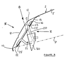
- a hood top (or bonnet) 1 for a motor vehicle is held shut by a releasable latch mechanism, part of which is illustrated in Figures 4 and 5, which engages with a striker 20 secured towards the front of the hood top.
- the latch mechanism When the latch mechanism is released, the hood top may be tilted about a hinge axis 3 ( Figure 1).
- the hood top 1 comprises an outer panel 2, which is symmetrical about a longitudinal vertical central plane, and has an upper surface 5 that extends forwardly from a transverse trailing edge 6, generally parallel to the common plane P of the hinge axis 3 and the point of engagement 4 of the striker and the latch mechanism 30.
- a front surface 8 of the outer panel 2 extends upwardly and rearwardly from a transverse lower leading edge 10 of the hood top 1 at an angle of about 45° to the plane P.
- the upper and front surfaces 5 and 8 meet at a transverse upper leading edge 12.
- An inner panel 13 is secured to the outer panel 2 by spot welds and clinches.
- the inner panel 13 carries mounting plates for hinges towards the transverse trailing edge 6 of the outer panel.
- part of the inner panel 13 in the central region of the hood top 1 immediately to the rear of the front surface 8 of the outer panel is disposed generally parallel to the front surface 8.
- This part of the inner panel 13 has a rectangular aperture 15 ( Figures 4 and 5) which is surrounded by a mounting plate 16 secured to the surface of the inner panel 13 that faces the outer panel 2 by eight spot welded joints 14 indicated by crosses in Figure 4.
- the striker 20 for the latch mechanism comprising a bar shaped to form an open loop 21 secured to the mounting plate 16 so that the loop 21 projects inwardly through the aperture 15 in the inner panel 13.
- the striker 20 terminates in legs 22, 23 which are secured to the inner panel by welded joints indicated by the shaded areas 25 in Figures 3 and 4.
- the legs 22, 23 lie in the same plane as the loop 21 and are secured so that they lie in a plane parallel to the central plane of the hood top 1.
- the welded joints 14 and 25 all lie in planes parallel to the part of the inner panel 13 shown in Figure 4.
- a latch mechanism part of which is illustrated at 30 in Figures 3 and 5 comprises a bracket 31 bolted to a cross-member (not shown) on the motor vehicle body.
- the bracket 31 defines a recess 33 for receiving the loop 21 of the striker 20.
- the recess 33 lies generally at right angles to the plane P.
- angle C is about 45°.
- the precise angle chosen in any particular case will depend on the space available for installation of the striker, which in turn depends on the shape of the outer panel 2 of the hood top 1.
- the angle C is preferably no more than 65° and desirably less than 50°.
Landscapes
- Superstructure Of Vehicle (AREA)
- Ventilation (AREA)
Claims (7)
Priority Applications (1)
| Application Number | Priority Date | Filing Date | Title |
|---|---|---|---|
| AT88303363T ATE60556T1 (de) | 1987-04-14 | 1988-04-14 | Motorhaube fuer ein motorfahrzeug. |
Applications Claiming Priority (2)
| Application Number | Priority Date | Filing Date | Title |
|---|---|---|---|
| GB08708919A GB2203389A (en) | 1987-04-14 | 1987-04-14 | Hood top or bonnet for a motor vehicle |
| GB8708919 | 1987-04-14 |
Publications (2)
| Publication Number | Publication Date |
|---|---|
| EP0288210A1 EP0288210A1 (de) | 1988-10-26 |
| EP0288210B1 true EP0288210B1 (de) | 1991-01-30 |
Family
ID=10615802
Family Applications (1)
| Application Number | Title | Priority Date | Filing Date |
|---|---|---|---|
| EP88303363A Expired - Lifetime EP0288210B1 (de) | 1987-04-14 | 1988-04-14 | Motorhaube für ein Motorfahrzeug |
Country Status (5)
| Country | Link |
|---|---|
| EP (1) | EP0288210B1 (de) |
| AT (1) | ATE60556T1 (de) |
| DE (1) | DE3861697D1 (de) |
| ES (1) | ES2020328B3 (de) |
| GB (1) | GB2203389A (de) |
Families Citing this family (1)
| Publication number | Priority date | Publication date | Assignee | Title |
|---|---|---|---|---|
| FR2930578B1 (fr) * | 2008-04-25 | 2010-04-23 | Coutier Moulage Gen Ind | Mecanisme de gache |
Family Cites Families (5)
| Publication number | Priority date | Publication date | Assignee | Title |
|---|---|---|---|---|
| GB733985A (en) * | 1952-11-07 | 1955-07-20 | Gen Motors Corp | Improvements in bonnet latch mechanisms for motor vehicles |
| GB998645A (en) * | 1963-04-02 | 1965-07-21 | Standard Pressed Steel Co | Improvements in and relating to vehicle bonnet mounting and fastener means |
| DE2031583A1 (de) * | 1970-06-26 | 1971-12-30 | Dr.-Ing. H.C. F. Porsche Kg, 7000 Stuttgart-Zuffenhausen | Haube für Kraftfahrzeuge |
| JPS5910682A (ja) * | 1982-07-09 | 1984-01-20 | 日産自動車株式会社 | 自動車用スライドドアのロツク装置 |
| DE3532095A1 (de) * | 1985-04-26 | 1986-11-06 | Webasto-Werk W. Baier GmbH & Co, 8035 Gauting | Schiebedach fuer fahrzeuge |
-
1987
- 1987-04-14 GB GB08708919A patent/GB2203389A/en not_active Withdrawn
-
1988
- 1988-04-14 EP EP88303363A patent/EP0288210B1/de not_active Expired - Lifetime
- 1988-04-14 AT AT88303363T patent/ATE60556T1/de not_active IP Right Cessation
- 1988-04-14 DE DE8888303363T patent/DE3861697D1/de not_active Expired - Lifetime
- 1988-04-14 ES ES88303363T patent/ES2020328B3/es not_active Expired - Lifetime
Also Published As
| Publication number | Publication date |
|---|---|
| DE3861697D1 (de) | 1991-03-07 |
| GB8708919D0 (en) | 1987-05-20 |
| GB2203389A (en) | 1988-10-19 |
| EP0288210A1 (de) | 1988-10-26 |
| ATE60556T1 (de) | 1991-02-15 |
| ES2020328B3 (es) | 1991-08-01 |
Similar Documents
| Publication | Publication Date | Title |
|---|---|---|
| US5115878A (en) | Hood structure for a vehicle | |
| US6814401B2 (en) | Vehicle part mounting structure | |
| JPH0325083A (ja) | バンパ取付部構造 | |
| US4930758A (en) | Support element with movement limiter, in particular for motor vehicle engines | |
| EP0288210B1 (de) | Motorhaube für ein Motorfahrzeug | |
| JP3800601B2 (ja) | 車両におけるフードロックストライカの取付構造 | |
| JP3646583B2 (ja) | フロントサイドメンバ構造 | |
| JPH0139393B2 (de) | ||
| JPH0627499Y2 (ja) | 車両用デッキクロスメンバ支持部構造 | |
| JPH0481322A (ja) | 自動車のドア | |
| JP2554130B2 (ja) | 自動車ボデー構造 | |
| JP2775894B2 (ja) | 自動車のフロントバンパーステイ取付構造 | |
| JPS6328707Y2 (de) | ||
| JPH0939847A (ja) | バックドアスポイラーの取付構造 | |
| JP2554439Y2 (ja) | ドアストライカーの取付構造 | |
| JPH0327907Y2 (de) | ||
| JP2997212B2 (ja) | 車両のドア構造 | |
| JPH0232497Y2 (de) | ||
| JPH0626468Y2 (ja) | 自動車のフロントボディ構造 | |
| JP2530543Y2 (ja) | トラクターのキャビンドア | |
| KR900008136Y1 (ko) | 모히칸형(Mohican type)의 루우프구조로 된 승용자동차의 센터필러구조 | |
| KR960009994Y1 (ko) | 자동차의 a필라 보강재 | |
| KR200148462Y1 (ko) | 테일 게이트 스트라이커 보강 장치 | |
| JP2795039B2 (ja) | 自動車のボデーマウント構造 | |
| JP2574189Y2 (ja) | 開閉板の緩衝機構 |
Legal Events
| Date | Code | Title | Description |
|---|---|---|---|
| PUAI | Public reference made under article 153(3) epc to a published international application that has entered the european phase |
Free format text: ORIGINAL CODE: 0009012 |
|
| AK | Designated contracting states |
Kind code of ref document: A1 Designated state(s): AT BE CH DE ES FR GB IT LI NL SE |
|
| 17P | Request for examination filed |
Effective date: 19890403 |
|
| 17Q | First examination report despatched |
Effective date: 19900116 |
|
| GRAA | (expected) grant |
Free format text: ORIGINAL CODE: 0009210 |
|
| AK | Designated contracting states |
Kind code of ref document: B1 Designated state(s): AT BE CH DE ES FR GB IT LI NL SE |
|
| REF | Corresponds to: |
Ref document number: 60556 Country of ref document: AT Date of ref document: 19910215 Kind code of ref document: T |
|
| ITF | It: translation for a ep patent filed | ||
| REF | Corresponds to: |
Ref document number: 3861697 Country of ref document: DE Date of ref document: 19910307 |
|
| ET | Fr: translation filed | ||
| PLBE | No opposition filed within time limit |
Free format text: ORIGINAL CODE: 0009261 |
|
| STAA | Information on the status of an ep patent application or granted ep patent |
Free format text: STATUS: NO OPPOSITION FILED WITHIN TIME LIMIT |
|
| 26N | No opposition filed | ||
| PGFP | Annual fee paid to national office [announced via postgrant information from national office to epo] |
Ref country code: AT Payment date: 19920409 Year of fee payment: 5 |
|
| PGFP | Annual fee paid to national office [announced via postgrant information from national office to epo] |
Ref country code: CH Payment date: 19920416 Year of fee payment: 5 |
|
| PGFP | Annual fee paid to national office [announced via postgrant information from national office to epo] |
Ref country code: NL Payment date: 19920430 Year of fee payment: 5 |
|
| REG | Reference to a national code |
Ref country code: FR Ref legal event code: DL |
|
| PG25 | Lapsed in a contracting state [announced via postgrant information from national office to epo] |
Ref country code: AT Effective date: 19930414 |
|
| PG25 | Lapsed in a contracting state [announced via postgrant information from national office to epo] |
Ref country code: CH Effective date: 19930430 Ref country code: LI Effective date: 19930430 |
|
| PG25 | Lapsed in a contracting state [announced via postgrant information from national office to epo] |
Ref country code: NL Effective date: 19931101 |
|
| NLV4 | Nl: lapsed or anulled due to non-payment of the annual fee | ||
| REG | Reference to a national code |
Ref country code: CH Ref legal event code: PL |
|
| EAL | Se: european patent in force in sweden |
Ref document number: 88303363.1 |
|
| PGFP | Annual fee paid to national office [announced via postgrant information from national office to epo] |
Ref country code: ES Payment date: 19950412 Year of fee payment: 8 |
|
| PG25 | Lapsed in a contracting state [announced via postgrant information from national office to epo] |
Ref country code: ES Free format text: LAPSE BECAUSE OF NON-PAYMENT OF DUE FEES Effective date: 19960415 |
|
| PGFP | Annual fee paid to national office [announced via postgrant information from national office to epo] |
Ref country code: SE Payment date: 19990325 Year of fee payment: 12 |
|
| PGFP | Annual fee paid to national office [announced via postgrant information from national office to epo] |
Ref country code: BE Payment date: 19990414 Year of fee payment: 12 Ref country code: FR Payment date: 19990414 Year of fee payment: 12 |
|
| REG | Reference to a national code |
Ref country code: ES Ref legal event code: FD2A Effective date: 19990405 |
|
| PG25 | Lapsed in a contracting state [announced via postgrant information from national office to epo] |
Ref country code: SE Free format text: LAPSE BECAUSE OF NON-PAYMENT OF DUE FEES Effective date: 20000415 |
|
| PG25 | Lapsed in a contracting state [announced via postgrant information from national office to epo] |
Ref country code: BE Free format text: LAPSE BECAUSE OF NON-PAYMENT OF DUE FEES Effective date: 20000430 |
|
| REG | Reference to a national code |
Ref country code: FR Ref legal event code: TP Ref country code: FR Ref legal event code: CD |
|
| BERE | Be: lapsed |
Owner name: FORD MOTOR CY LTD Effective date: 20000430 |
|
| EUG | Se: european patent has lapsed |
Ref document number: 88303363.1 |
|
| PG25 | Lapsed in a contracting state [announced via postgrant information from national office to epo] |
Ref country code: FR Free format text: LAPSE BECAUSE OF NON-PAYMENT OF DUE FEES Effective date: 20001229 |
|
| REG | Reference to a national code |
Ref country code: FR Ref legal event code: ST |
|
| REG | Reference to a national code |
Ref country code: GB Ref legal event code: IF02 |
|
| PGFP | Annual fee paid to national office [announced via postgrant information from national office to epo] |
Ref country code: GB Payment date: 20070313 Year of fee payment: 20 |
|
| REG | Reference to a national code |
Ref country code: GB Ref legal event code: 746 Effective date: 20070316 |
|
| PGFP | Annual fee paid to national office [announced via postgrant information from national office to epo] |
Ref country code: DE Payment date: 20070430 Year of fee payment: 20 |
|
| PGFP | Annual fee paid to national office [announced via postgrant information from national office to epo] |
Ref country code: IT Payment date: 20070616 Year of fee payment: 20 |
|
| REG | Reference to a national code |
Ref country code: GB Ref legal event code: PE20 Expiry date: 20080413 |
|
| PG25 | Lapsed in a contracting state [announced via postgrant information from national office to epo] |
Ref country code: GB Free format text: LAPSE BECAUSE OF EXPIRATION OF PROTECTION Effective date: 20080413 |