EP0287823A1 - Instrument chirurgical - Google Patents
Instrument chirurgical Download PDFInfo
- Publication number
- EP0287823A1 EP0287823A1 EP88104527A EP88104527A EP0287823A1 EP 0287823 A1 EP0287823 A1 EP 0287823A1 EP 88104527 A EP88104527 A EP 88104527A EP 88104527 A EP88104527 A EP 88104527A EP 0287823 A1 EP0287823 A1 EP 0287823A1
- Authority
- EP
- European Patent Office
- Prior art keywords
- instrument according
- gear
- handle
- shaft
- pawl
- Prior art date
- Legal status (The legal status is an assumption and is not a legal conclusion. Google has not performed a legal analysis and makes no representation as to the accuracy of the status listed.)
- Granted
Links
Images
Classifications
-
- A—HUMAN NECESSITIES
- A61—MEDICAL OR VETERINARY SCIENCE; HYGIENE
- A61B—DIAGNOSIS; SURGERY; IDENTIFICATION
- A61B17/00—Surgical instruments, devices or methods, e.g. tourniquets
- A61B17/56—Surgical instruments or methods for treatment of bones or joints; Devices specially adapted therefor
- A61B17/58—Surgical instruments or methods for treatment of bones or joints; Devices specially adapted therefor for osteosynthesis, e.g. bone plates, screws, setting implements or the like
- A61B17/88—Osteosynthesis instruments; Methods or means for implanting or extracting internal or external fixation devices
- A61B17/8875—Screwdrivers, spanners or wrenches
-
- B—PERFORMING OPERATIONS; TRANSPORTING
- B25—HAND TOOLS; PORTABLE POWER-DRIVEN TOOLS; MANIPULATORS
- B25B—TOOLS OR BENCH DEVICES NOT OTHERWISE PROVIDED FOR, FOR FASTENING, CONNECTING, DISENGAGING OR HOLDING
- B25B15/00—Screwdrivers
- B25B15/02—Screwdrivers operated by rotating the handle
- B25B15/04—Screwdrivers operated by rotating the handle with ratchet action
Definitions
- the invention relates to a surgical hand instrument, in particular for osteosynthesis with a handle to which a tool, such as a screwdriver blade, drilling tool, thread cutter, is attached.
- a tool such as a screwdriver blade, drilling tool, thread cutter
- the invention has improved the used in surgery Hand instruments made to the task that they allow a much faster work.
- the present invention is concerned with the design of the handle. Therefore, it is basically irrelevant which specific tool is or can be attached to it.
- a shaft is rotatably mounted coaxially in the handle, on the outer end of which the tool is attached.
- On this shaft there are two gears at a distance within the handle as well as a pawl that can be operated from the outside.
- the pawl engages in the ring gear of one gear and releases the other gear, whereas vice versa, i.e. is engaged in the ring gear of the other gear in the other end position.
- the ring gear of both gears has a sawtooth profile, i.e. a profile in which one flank runs essentially in the radial direction and the other at an acute angle thereto, the flanks of the same slope lying on opposite sides.
- the locking of the two gears is carried out in the opposite direction of rotation.
- the gear wheel is prevented from rotating in one direction; when moving in opposite direction direction, the pawl is pushed outwards and movement is therefore permitted.
- the rotation is blocked in one direction and released in the other opposite direction.
- the respective direction of rotation is determined by the position of the pawl, the actuation of which makes it possible to reverse the movement. This allows, for example, when screwing in screws through the corresponding position of the pawl, that the shaft is locked by the pawl at the one which is usually clockwise to insert the screws, so that the rotation of the handle is transmitted to the blade or screw.
- the invention considers it ideal to choose the step width relatively narrow when screwing in screws, so that sensitive screwing in and tightening is made possible by the small spacing of the individual teeth of the ring gear from one another.
- the small increment causes the formation of correspondingly narrow and slender teeth, the strength and maximum load capacity of which is then comparatively low.
- To screw in the screws relatively small forces have to be applied, but a sensitive and dosed screwing in is of considerable advantage.
- sol large moments can be applied when unscrewing the screws.
- one of the gearwheels used for turning in will be provided with a comparatively small step size, while the other one used for turning out will be provided with a relatively large increment.
- narrow increments are specifically achieved by installing two coaxial gear rollers instead of a gearwheel with toothed rings which are offset azimuthally from one another and to which a pawl is assigned for each direction of rotation.
- This allows an effective reduction and in particular halving of the step sizes while maintaining the shape of the toothed rings of the individual gear rollers. Due to the retention of the shape of the sprockets, the possible force for support and the maximum load capacity remain unchanged, although the step sizes decrease.
- This pair of gear rollers can take the place of one or both gears.
- the structural design of the pawl is basically arbitrary within the scope of the invention.
- it consists of platelets, each of which can be pivoted about an axis running in the grip like a chord, and which engage in a gearwheel.
- the number of platelets is determined by the total number of gears or gear rollers.
- a slide is movably arranged in the handle, the shape of which requires that a plate is pivoted out of the ring gear in the respective end position.
- the other plate is in engagement with the ring gear and causes a lock when moving in one direction of rotation and is lifted when rotating in the opposite direction, so that the gear and thus the shaft can be moved freely.
- the actuation is arranged in the front part of the handle. It is then possible to switch and reverse the direction of rotation without loosening and releasing the handle.
- the shaft is connected to a torque limiter.
- its task is to separate the connection between the handle and the shaft when a certain torque is exceeded and not to pass on the torque exerted on the handle to the blade.
- the invention proposes a torque limiter which consists of two clutch disks pressed against one another, one of which is connected to the shaft and the other to the handle. The connection is loosened and the shaft is separated from the handle by partially slight displacements of the clutch disks in the axial direction.
- the clutch disks can be provided with a tooth profile that points towards one another, which in the special case of the sawtooth profile responds only in one direction when twisted, the clutch disks being pressed against one another by springs.
- the direction of the sawtooth profile will be chosen so that the torque limiter responds only when screwing in, but is deactivated when it is unscrewed, i.e. in the opposite direction.
- spring-loaded balls engage in grooves or ring gears.
- a change in the triggering moment can be achieved if the pretension of the spring pressing the clutch discs against one another is adjusted, for example, by displacing the counter bearing of the spring relative to the clutch, so that the spring experiences a change in its length and, consequently, in its tension.
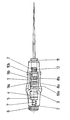
- the part which is decisive for the present invention is located approximately in the middle third of the handle 1. It consists of two spaced-apart gear wheels 8a, 8b fastened on the shaft 2. Both differ in their differently shaped ring gear, i.e. both have a sawtooth profile, which, however, is oriented towards one another, that is to say that the flanks of the same rise in both gearwheels 8a, 8b lie on opposite sides.
- Each gear wheel 8a, 8b is assigned in each case in platelets 9a, 9b, which engages in the associated gear ring in the axial direction of the shaft 2.
- Both plates can be pivoted about an axis 10 a, b extending in the manner of a segment to the shaft 2 or handle 1, which allows the respective plate 9 to be lifted out of the toothed ring of the gear wheel 8 and released for rotation.
- the rotation of the shaft 2 is only released in one direction of rotation depending on the sawtooth profile of the other gear, but fixed in the opposite direction. The result of this is that when the handle 1 is rotated in one direction, the shaft 2 is fixed in space, but when it is rotated in the opposite direction by engagement of the associated plate 9 in the associated gear 8.
- This direction of rotation can be reversed in that the other opposing plate 9 is brought into engagement position by a device not shown here, for example by a slide, and the previous opposing plate is released. It is crucial for the invention that in one end position one of the two gears 8a, b always engages one of the plates 9a, b, but the opposite one is released.
- the slide (not shown here) and the plates 9 form a pawl in their entirety from a functional point of view, from which one of the two plates 9a, 9b releases the associated gear 8a, 8b, but the other plate 9b, 9a into the associated gear 8b, 8a engages and thereby defines the direction of rotation, in which the handle 1 takes the shaft 2 with it.
- the advantage of the arrangement according to the invention is that the hand encloses the handle 1 and can set it in an oscillatory reciprocating motion, thereby the tool in one Direction moves without the need for repositioning. By switching the locking link, the shaft 2 can be moved in the opposite direction with the same handling.
- the device thus allows a quick and exact work while maintaining a precise alignment without having to reach around. This is particularly important for operational purposes such as that of osteosynthesis.
- a quick-change device 11 which can be moved in the axial direction of the shaft 2 and is supported on a spring 12.
- the task of the quick-change device is to establish a connection to the tool attached to the handle 1, which includes screwdriver blades, drills, taps and other tools. It serves to hold the tool and thereby to establish a connection to the shaft 2 mounted coaxially in the handle 1.
- the quick-change device is intended to enable the individual tools to be replaced quickly and is of conventional design.
Landscapes
- Health & Medical Sciences (AREA)
- Surgery (AREA)
- Engineering & Computer Science (AREA)
- Orthopedic Medicine & Surgery (AREA)
- Life Sciences & Earth Sciences (AREA)
- Heart & Thoracic Surgery (AREA)
- Nuclear Medicine, Radiotherapy & Molecular Imaging (AREA)
- Biomedical Technology (AREA)
- Mechanical Engineering (AREA)
- Medical Informatics (AREA)
- Molecular Biology (AREA)
- Animal Behavior & Ethology (AREA)
- General Health & Medical Sciences (AREA)
- Public Health (AREA)
- Veterinary Medicine (AREA)
- Surgical Instruments (AREA)
- Details Of Spanners, Wrenches, And Screw Drivers And Accessories (AREA)
Priority Applications (1)
| Application Number | Priority Date | Filing Date | Title |
|---|---|---|---|
| AT88104527T ATE91609T1 (de) | 1987-03-25 | 1988-03-22 | Chirurgisches handinstrument. |
Applications Claiming Priority (2)
| Application Number | Priority Date | Filing Date | Title |
|---|---|---|---|
| DE3709824 | 1987-03-25 | ||
| DE19873709824 DE3709824A1 (de) | 1987-03-25 | 1987-03-25 | Chirurgisches handinstrument |
Publications (2)
| Publication Number | Publication Date |
|---|---|
| EP0287823A1 true EP0287823A1 (fr) | 1988-10-26 |
| EP0287823B1 EP0287823B1 (fr) | 1993-07-21 |
Family
ID=6323957
Family Applications (1)
| Application Number | Title | Priority Date | Filing Date |
|---|---|---|---|
| EP88104527A Expired - Lifetime EP0287823B1 (fr) | 1987-03-25 | 1988-03-22 | Instrument chirurgical |
Country Status (3)
| Country | Link |
|---|---|
| EP (1) | EP0287823B1 (fr) |
| AT (1) | ATE91609T1 (fr) |
| DE (2) | DE3709824A1 (fr) |
Cited By (6)
| Publication number | Priority date | Publication date | Assignee | Title |
|---|---|---|---|---|
| EP0607688A1 (fr) * | 1992-12-21 | 1994-07-27 | Seth Lowell Dr. Neubardt | Procédure et système d'insertion d'une vis vertébrale pédiculaire |
| US5474558A (en) * | 1992-04-30 | 1995-12-12 | Neubardt; Seth L. | Procedure and system for spinal pedicle screw insertion |
| FR2795624A1 (fr) | 1999-07-01 | 2001-01-05 | Vanacker Gerard | Procede de forage du pedicule vertebral notamment pour la mise en place d'une vis pediculaire, instrument pour la mise en oeuvre d'un tel procede |
| EP1110512A1 (fr) * | 1999-12-20 | 2001-06-27 | Sulzer Orthopedics Ltd. | Porte-outil médical avec limitation de couple |
| CN105232124A (zh) * | 2015-10-13 | 2016-01-13 | 广州聚生生物科技有限公司 | 一种徒手置钉外固定系统 |
| EP2969395A4 (fr) * | 2013-03-12 | 2016-03-16 | Eca Medical Instr | Clé dynamométrique à cliquet |
Families Citing this family (3)
| Publication number | Priority date | Publication date | Assignee | Title |
|---|---|---|---|---|
| US20070006692A1 (en) * | 2005-07-11 | 2007-01-11 | Phan Christopher U | Torque limiting device |
| US8021366B2 (en) | 2005-07-11 | 2011-09-20 | Kyphon Sarl | Axial load limiting system and methods |
| CN104173093B (zh) * | 2013-05-22 | 2017-10-13 | 天津瑞奇外科器械股份有限公司 | 超声刀刀头和超声刀 |
Citations (4)
| Publication number | Priority date | Publication date | Assignee | Title |
|---|---|---|---|---|
| DE39923C (de) * | O. TANNENBERG in Dresden, Feld | Schraubenzieher mit Sperrwerk | ||
| GB196759A (en) * | 1922-03-01 | 1923-05-03 | John Henry Charlton | Improvements in or connected with screw drivers or like small tools |
| US2486043A (en) * | 1946-04-12 | 1949-10-25 | Carl W Lofgren | Reversible ratchet mechanism |
| US4517865A (en) * | 1984-01-06 | 1985-05-21 | Huang Yung Lung | Torque-adjustable screwdriver |
Family Cites Families (3)
| Publication number | Priority date | Publication date | Assignee | Title |
|---|---|---|---|---|
| GB1324164A (en) * | 1969-10-02 | 1973-07-18 | Brummelkamp R | Screw drivers |
| JPS54140296A (en) * | 1978-04-19 | 1979-10-31 | Post Melvin | Screw driver |
| DD238724A1 (de) * | 1985-06-28 | 1986-09-03 | Rohrkombinat Stahl & Walzwerk | Medizinischer schraubendreher |
-
1987
- 1987-03-25 DE DE19873709824 patent/DE3709824A1/de not_active Withdrawn
-
1988
- 1988-03-22 EP EP88104527A patent/EP0287823B1/fr not_active Expired - Lifetime
- 1988-03-22 AT AT88104527T patent/ATE91609T1/de not_active IP Right Cessation
- 1988-03-22 DE DE8888104527T patent/DE3882415D1/de not_active Expired - Fee Related
Patent Citations (4)
| Publication number | Priority date | Publication date | Assignee | Title |
|---|---|---|---|---|
| DE39923C (de) * | O. TANNENBERG in Dresden, Feld | Schraubenzieher mit Sperrwerk | ||
| GB196759A (en) * | 1922-03-01 | 1923-05-03 | John Henry Charlton | Improvements in or connected with screw drivers or like small tools |
| US2486043A (en) * | 1946-04-12 | 1949-10-25 | Carl W Lofgren | Reversible ratchet mechanism |
| US4517865A (en) * | 1984-01-06 | 1985-05-21 | Huang Yung Lung | Torque-adjustable screwdriver |
Cited By (9)
| Publication number | Priority date | Publication date | Assignee | Title |
|---|---|---|---|---|
| US5474558A (en) * | 1992-04-30 | 1995-12-12 | Neubardt; Seth L. | Procedure and system for spinal pedicle screw insertion |
| EP0607688A1 (fr) * | 1992-12-21 | 1994-07-27 | Seth Lowell Dr. Neubardt | Procédure et système d'insertion d'une vis vertébrale pédiculaire |
| FR2795624A1 (fr) | 1999-07-01 | 2001-01-05 | Vanacker Gerard | Procede de forage du pedicule vertebral notamment pour la mise en place d'une vis pediculaire, instrument pour la mise en oeuvre d'un tel procede |
| WO2001001875A1 (fr) | 1999-07-01 | 2001-01-11 | Spinevision S.A. | Procede de forage et instrument pour la mise en place d'une vis pediculaire |
| EP1110512A1 (fr) * | 1999-12-20 | 2001-06-27 | Sulzer Orthopedics Ltd. | Porte-outil médical avec limitation de couple |
| EP2969395A4 (fr) * | 2013-03-12 | 2016-03-16 | Eca Medical Instr | Clé dynamométrique à cliquet |
| US9446507B2 (en) | 2013-03-12 | 2016-09-20 | Eca Medical Instruments | Ratcheting torque wrench |
| US10195724B2 (en) | 2013-03-12 | 2019-02-05 | Eca Medical Instruments | Ratcheting torque wrench |
| CN105232124A (zh) * | 2015-10-13 | 2016-01-13 | 广州聚生生物科技有限公司 | 一种徒手置钉外固定系统 |
Also Published As
| Publication number | Publication date |
|---|---|
| ATE91609T1 (de) | 1993-08-15 |
| DE3882415D1 (de) | 1993-08-26 |
| DE3709824A1 (de) | 1988-10-06 |
| EP0287823B1 (fr) | 1993-07-21 |
Similar Documents
| Publication | Publication Date | Title |
|---|---|---|
| DE19705378C2 (de) | Kupplungsmechanismus zur Verwendung in einem energiebetriebenen Werkzeug | |
| EP0521259B1 (fr) | Machine-outil portative | |
| DE69930339T2 (de) | Umkehrbares Ratschenwerkzeug mit Zahnrad/Sperrklinken Eingriff | |
| EP0710520B1 (fr) | Mandrin porte-foret | |
| DE102007024373B4 (de) | Mittels einer geneigten Keilfläche gesperrtes Bohrfutter | |
| EP1737616B1 (fr) | Outil a main a commande de puissance, a dispositif de fixation pour un outil | |
| DE4238464C1 (de) | Selbstspannendes Bohrfutter | |
| DE10303235B4 (de) | Drehmomentübertragungsmechanismen und Motorwerkzeuge mit solchen Drehmomentübertragungsmechanismen | |
| DE10258372B4 (de) | Spannaufbau | |
| DE4211838A1 (de) | Werkzeug-Spannfutter | |
| DE10333124A1 (de) | Ratschenschlüssel mit Schnell-Anzieh/Löse-Funktion und Fein-Einstell-Funktion | |
| EP0401548A1 (fr) | Dispositif à outil de vissage | |
| EP0622143A1 (fr) | Mandrin de perceuse | |
| DE4129048A1 (de) | Bohrfutter | |
| EP1140400B1 (fr) | Outil a enlevement de copeaux pour usinage a vitesse elevee | |
| DE102006054190A1 (de) | Werkzeugratsche | |
| EP0287823B1 (fr) | Instrument chirurgical | |
| DE19725597A1 (de) | Zange zum Anbringen bzw. Entfernen von Sicherunsringen für eine Welle wie auch für Sicherungsringe für eine Bohrung | |
| DE2628984A1 (de) | Werkzeug, insbesondere rohrschneider | |
| EP0175065B1 (fr) | Mandrin réglable | |
| EP3641987B1 (fr) | Bride de fixation et procédé de fonctionnement d'une bride de fixation | |
| DE1947102A1 (de) | Elektrisch angetriebener Ratschen-Schraubschluessel | |
| DE3315661C2 (de) | Spannfutter für ein Werkzeug zum Schlagbohren | |
| DE3416946C1 (de) | Schlagbohreinrichtung | |
| DE102005046649B4 (de) | Ringschlüssel mit Schnelldrehvorrichtung |
Legal Events
| Date | Code | Title | Description |
|---|---|---|---|
| PUAI | Public reference made under article 153(3) epc to a published international application that has entered the european phase |
Free format text: ORIGINAL CODE: 0009012 |
|
| AK | Designated contracting states |
Kind code of ref document: A1 Designated state(s): AT CH DE ES FR GB IT LI NL SE |
|
| 17P | Request for examination filed |
Effective date: 19890202 |
|
| 17Q | First examination report despatched |
Effective date: 19910925 |
|
| GRAA | (expected) grant |
Free format text: ORIGINAL CODE: 0009210 |
|
| AK | Designated contracting states |
Kind code of ref document: B1 Designated state(s): AT CH DE ES FR GB IT LI NL SE |
|
| PG25 | Lapsed in a contracting state [announced via postgrant information from national office to epo] |
Ref country code: IT Free format text: LAPSE BECAUSE OF FAILURE TO SUBMIT A TRANSLATION OF THE DESCRIPTION OR TO PAY THE FEE WITHIN THE PRE;WARNING: LAPSES OF ITALIAN PATENTS WITH EFFECTIVE DATE BEFORE 2007 MAY HAVE OCCURRED AT ANY TIME BEFORE 2007. THE CORRECT EFFECTIVE DATE MAY BE DIFFERENT FROM THE ONE RECORDED.SCRIBED TIME-LIMIT Effective date: 19930721 Ref country code: GB Effective date: 19930721 Ref country code: NL Effective date: 19930721 Ref country code: ES Free format text: THE PATENT HAS BEEN ANNULLED BY A DECISION OF A NATIONAL AUTHORITY Effective date: 19930721 Ref country code: FR Effective date: 19930721 Ref country code: SE Effective date: 19930721 |
|
| REF | Corresponds to: |
Ref document number: 91609 Country of ref document: AT Date of ref document: 19930815 Kind code of ref document: T |
|
| REF | Corresponds to: |
Ref document number: 3882415 Country of ref document: DE Date of ref document: 19930826 |
|
| EN | Fr: translation not filed | ||
| NLV1 | Nl: lapsed or annulled due to failure to fulfill the requirements of art. 29p and 29m of the patents act | ||
| GBV | Gb: ep patent (uk) treated as always having been void in accordance with gb section 77(7)/1977 [no translation filed] |
Effective date: 19930721 |
|
| PG25 | Lapsed in a contracting state [announced via postgrant information from national office to epo] |
Ref country code: AT Effective date: 19940322 |
|
| PG25 | Lapsed in a contracting state [announced via postgrant information from national office to epo] |
Ref country code: LI Effective date: 19940331 Ref country code: CH Effective date: 19940331 |
|
| PLBE | No opposition filed within time limit |
Free format text: ORIGINAL CODE: 0009261 |
|
| STAA | Information on the status of an ep patent application or granted ep patent |
Free format text: STATUS: NO OPPOSITION FILED WITHIN TIME LIMIT |
|
| 26N | No opposition filed | ||
| REG | Reference to a national code |
Ref country code: CH Ref legal event code: PL |
|
| PGFP | Annual fee paid to national office [announced via postgrant information from national office to epo] |
Ref country code: DE Payment date: 20060330 Year of fee payment: 19 |
|
| PG25 | Lapsed in a contracting state [announced via postgrant information from national office to epo] |
Ref country code: DE Free format text: LAPSE BECAUSE OF NON-PAYMENT OF DUE FEES Effective date: 20071002 |