EP0287563B1 - Verfahren zum perforieren und drucktuch für rotationsdruckmaschine mit perforiereinrichtung, zum beispiel offsetpresse - Google Patents
Verfahren zum perforieren und drucktuch für rotationsdruckmaschine mit perforiereinrichtung, zum beispiel offsetpresse Download PDFInfo
- Publication number
- EP0287563B1 EP0287563B1 EP19870900174 EP87900174A EP0287563B1 EP 0287563 B1 EP0287563 B1 EP 0287563B1 EP 19870900174 EP19870900174 EP 19870900174 EP 87900174 A EP87900174 A EP 87900174A EP 0287563 B1 EP0287563 B1 EP 0287563B1
- Authority
- EP
- European Patent Office
- Prior art keywords
- blanket
- groove
- printing
- cylinder
- small bar
- Prior art date
- Legal status (The legal status is an assumption and is not a legal conclusion. Google has not performed a legal analysis and makes no representation as to the accuracy of the status listed.)
- Expired - Lifetime
Links
- 238000000034 method Methods 0.000 title claims abstract description 25
- 238000005520 cutting process Methods 0.000 claims abstract description 20
- 239000000463 material Substances 0.000 claims abstract description 7
- 239000000853 adhesive Substances 0.000 claims description 8
- 241000446313 Lamella Species 0.000 claims description 5
- 229910001369 Brass Inorganic materials 0.000 claims description 2
- 239000004972 Polyurethane varnish Substances 0.000 claims description 2
- 239000010951 brass Substances 0.000 claims description 2
- 239000011248 coating agent Substances 0.000 claims 1
- 238000000576 coating method Methods 0.000 claims 1
- 239000011888 foil Substances 0.000 claims 1
- 238000004080 punching Methods 0.000 description 8
- 230000001070 adhesive effect Effects 0.000 description 3
- 229920001971 elastomer Polymers 0.000 description 3
- 238000004519 manufacturing process Methods 0.000 description 2
- 239000002245 particle Substances 0.000 description 2
- 230000000149 penetrating effect Effects 0.000 description 2
- 230000035515 penetration Effects 0.000 description 2
- 239000007779 soft material Substances 0.000 description 2
- 229910000831 Steel Inorganic materials 0.000 description 1
- 238000009825 accumulation Methods 0.000 description 1
- 238000004026 adhesive bonding Methods 0.000 description 1
- 238000004140 cleaning Methods 0.000 description 1
- 239000003086 colorant Substances 0.000 description 1
- 230000007547 defect Effects 0.000 description 1
- 239000003599 detergent Substances 0.000 description 1
- 239000000806 elastomer Substances 0.000 description 1
- 230000001788 irregular Effects 0.000 description 1
- 230000001681 protective effect Effects 0.000 description 1
- 230000003014 reinforcing effect Effects 0.000 description 1
- 239000000565 sealant Substances 0.000 description 1
- 238000007493 shaping process Methods 0.000 description 1
- 239000010959 steel Substances 0.000 description 1
- 239000002699 waste material Substances 0.000 description 1
Images


Classifications
-
- B—PERFORMING OPERATIONS; TRANSPORTING
- B41—PRINTING; LINING MACHINES; TYPEWRITERS; STAMPS
- B41G—APPARATUS FOR BRONZE PRINTING, LINE PRINTING, OR FOR BORDERING OR EDGING SHEETS OR LIKE ARTICLES; AUXILIARY FOR PERFORATING IN CONJUNCTION WITH PRINTING
- B41G7/00—Auxiliary perforating apparatus associated with printing devices
Definitions
- the present invention relates to a blanket for a rotary printing machine, such as a sheetfed or continuous offset machine, equipped with a punching device.
- the most annoying drawback of this method of pre-cutting the sheets of paper lies in the fact that the teeth or cutting elements of the perforating nets penetrating into the soft material of the blanket, create blisters, at the level of the perforations, on the face of said sheets opposite to the penetrating face. After punching, the sheets of paper tend to bend slightly at the level of the punch line. In the case of the printing of sheets having a detachable useful surface and a narrow strip allowing their assembly, for example in the form of notebooks or bundles, the narrow strip of the sheets tends to lift slightly relative to the detachable useful surface of said leaves, instead of staying flat.
- the printed and perforated sheets are very poorly received and very poorly "jogged” or centered on the receiving plate, due to the lack of rigidity of said sheets which are slightly folded and of their blisters which hang on to each other, so that the stack of sheets stacked on said receiving tray is irregular and has one side higher than the other.
- the stacking height of the sheets is thereby reduced correspondingly, which leads to frequent changes of the receiving carriage and, consequently, to frequent machine stops.
- poorly stacked sheets can be easily damaged and made unusable, which results in significant loss of time when these sheets are numbered.
- the printed and perforated sheets are generally assembled in an automatic collator which must receive stacks of sheets perfectly “jogged” or centered and flat above, so that it is necessary to resume, by hand, “jogging "or centering improperly stacked sheets, which is another waste of time.
- the object of the invention is in particular to remedy the aforementioned drawbacks of the perforation process according to which the teeth or cutting elements of the perforating nets are carried by the printing cylinder and applied against the blanket.
- this object is achieved thanks to a blanket provided with at least one groove opening on its active external face or printing surface and in the bottom of which is housed a strip or strip made of a hard material. , this bar having an upper face against which the perforating or cutting elements of the perforating threads fixed on the printing cylinder of the machine are intended to come into pressure, during the printing process.
- the sharpness of the perforation means that, during the subsequent use of the bundles and, above all, the notebooks, it is very easy to detach several sheets at a time with a very nice appearance of the edge resulting from the pre-cutting of said sheets.
- rotary printing machines such as offset machines of all kinds mainly comprising ( Figure 1) a plate cylinder 1 with which are associated inking rollers 2 and dampening rollers 3, a blanket cylinder 4 and a printing cylinder 5 also called a pressure cylinder or margin cylinder, a feeding station 6 receiving the stacks of blank sheets 7 to be printed, and a receiving tray 8 on which are stacked the printed sheets, numbered and perforated 9, after their passage in the printing and punching assembly.
- a jogging device (not shown) ensures the correct stacking of the printed sheets, on the receiving tray.
- the blanket cylinder 4 is intended for the removable mounting of the flexible blanket 10 made of rubber or elastomer with a very fine grain and perfectly regular and on which the pattern deposited on the plate deposited on the plate cylinder 1 is deposited, during the printing process, this pattern then transfers to the sheets of paper.
- the blanket 10 is provided with at least one groove 11 opening on its printing face and in the bottom of which is housed a bar 12 made of a hard and non-compressible material.
- the position of the groove or grooves 11 provided with a non-compressible bar 12 is a function of the location of the perforations to be made on the printed sheets of paper.
- the groove 11 or each groove 11 is formed at a location intended to come into contact with the cutting elements of a perforating thread bonded to the printing cylinder, during the printing process, as is best seen from the which follows.
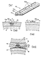
- a blanket 10 provided with a groove 11 with a reinforced bottom which is arranged parallel to the axis of the cylinders 1, 4, 5 when said blanket is installed on the blanket cylinder, while there is shown in Figure 3, a blanket 10 provided with two parallel grooves 11 with reinforced bottom which are arranged in the circumferential direction when said blanket is mounted on the blanket cylinder.
- the blanket can also be provided, at the same time, with one or more grooves with reinforced bottom oriented parallel to the axis of the cylinders, and with one or more grooves with reinforced bottom arranged in the circumferential direction, as shown in Figure 3.
- the groove or grooves with a reinforced bottom 11-12 can be formed in any part of the outer surface of the blanket, and in any orientation or pattern, as required. It suffices, prior to the execution of the groove (s), to wear the usual and necessary marks on the blanket and to dig the said groove (s) at the locations of these marks.
- the longitudinal walls 11a of the groove or of each groove 11 have a divergent orientation in the direction of the printing surface 10a of the blanket 10, as shown in particular in FIG. 6.
- the groove or each groove 11 can be executed during the manufacture of the blanket or later, as required, before use thereof.
- a layer 13 of a sealant such as a polyurethane varnish is applied to the bottom and the sides of the groove after it has been hollowed out. desired size and height, in order to ensure a permanent seal at this groove and thus to avoid detergents used for frequent cleaning of the blanket, being able to penetrate into the multi-layers of the latter.
- the non-compressible bar 12 constituting the reinforced bottom of the groove or of each groove 11, can be put in place during the manufacture of the blanket, or subsequently, as required, before use thereof.
- the bar 12 can be glued, in the bottom of the groove 11, in a removable manner, by means of an adhesive strip 14 provided with two opposite self-adhesive faces and having a width and a length identical to those of said bar.
- the double-sided adhesive strip 14 is fixed, by means of one of its self-adhesive faces, to the bottom of the groove, while the bar is glued to said adhesive strip by means of the second auto face. - sticky of the latter.
- the bar 12 forming the bottom of the groove 11 is formed by a strip of material that is not compressible or has a very low degree of malleability, but the hardness of which is however less than that of the teeth or cutting elements of the perforating nets intended to be glued to the printing cylinder 5 of the machine.
- the bar 12 can advantageously consist of a small blade or tinsel of brass.
- the upper face 12a of the non-compressible bar 12 housed in the groove 11 is set back relative to the active external surface or printing surface 10a of the blanket, so that a vacuum of height h is formed between said upper face 12a and the plane in which is located said printing surface 10a, so that the offset plate, installed on the plate cylinder 1, can unroll on said surface without encountering any relief.
- a perforating net 15 is removably fixed, for example by gluing, on the printing cylinder 5, at the desired location or locations, so that, during the rotation of the blanket cylinder 4 and of said printing cylinder, the teeth or cutting elements of said perforating net come to bear on the bar 12 reinforcing the bottom of the groove or grooves 11.
- an exemplary embodiment of a perforating net 15 may be used advantageously for the implementation of the method of the invention.
- This perforating net comprises a base 15a consisting of a steel strip, the lower face of which is provided with a self-adhesive strip or layer 15b, the lower face of the latter being covered, before use, by a detachable protective film 15c. On its upper face, the base 15a is provided with teeth or cutting elements 15d aligned in the longitudinal direction of said base.
- the distance h between the upper face 12a of the non-compressible bar 12 and the plane in which the active external face or printing surface 10a of the blanket 10 is included is barely less than or substantially equal to the height H of the perforating net 15 , so that sufficient pressure can be obtained from the end of the teeth or from the cutting edge of the cutting members 15d of said perforating thread on the upper face of said strip, making it possible to cut along the length of the teeth or a net perforation and perfect from the sheet of paper 16, without creating blisters or stain removal.
- FIG. 10 illustrates the implementation of the punching method of the invention.
- the sheet of paper 16 is pressed by the printing cylinder 5 provided with the perforating net 15, against the blanket 10 provided with a groove 11 equipped with a bar or non-compressible strip 12.
- the locations where said perforating net and said groove are placed come into tangential contact, the ends of the teeth or the cutting edges of the cutting elements of said perforating net are pressed against the upper face of the bar or lamella 12, which leads to sectioning. according to the length of the teeth or the clean and perfect perforation of the sheet of paper.
Landscapes
- Perforating, Stamping-Out Or Severing By Means Other Than Cutting (AREA)
- Printing Plates And Materials Therefor (AREA)
Claims (10)
Priority Applications (1)
| Application Number | Priority Date | Filing Date | Title |
|---|---|---|---|
| AT87900174T ATE57136T1 (de) | 1985-12-24 | 1986-12-23 | Verfahren zum perforieren und drucktuch fuer rotationsdruckmaschine mit perforiereinrichtung, zum beispiel offsetpresse. |
Applications Claiming Priority (2)
| Application Number | Priority Date | Filing Date | Title |
|---|---|---|---|
| FR8519367 | 1985-12-24 | ||
| FR8519367A FR2591943B1 (fr) | 1985-12-24 | 1985-12-24 | Procede de perforage et blanchet pour machine d'impression rotative equipee d'un dispositif ou d'un accessoire de perforage, par exemple pour machine offset |
Publications (2)
| Publication Number | Publication Date |
|---|---|
| EP0287563A1 EP0287563A1 (de) | 1988-10-26 |
| EP0287563B1 true EP0287563B1 (de) | 1990-10-03 |
Family
ID=9326277
Family Applications (1)
| Application Number | Title | Priority Date | Filing Date |
|---|---|---|---|
| EP19870900174 Expired - Lifetime EP0287563B1 (de) | 1985-12-24 | 1986-12-23 | Verfahren zum perforieren und drucktuch für rotationsdruckmaschine mit perforiereinrichtung, zum beispiel offsetpresse |
Country Status (5)
| Country | Link |
|---|---|
| EP (1) | EP0287563B1 (de) |
| AU (1) | AU6839087A (de) |
| DE (1) | DE3674807D1 (de) |
| FR (1) | FR2591943B1 (de) |
| WO (1) | WO1987003844A1 (de) |
Families Citing this family (3)
| Publication number | Priority date | Publication date | Assignee | Title |
|---|---|---|---|---|
| FR2710291B1 (fr) * | 1993-09-24 | 1995-11-17 | Walter Fruttiger | Procédé et dispositif pour la protection du blanchet d'une machine offset lors de l'utilisation de filets perforants, de filets coupeurs ou analogues. |
| GB0201471D0 (en) * | 2002-01-23 | 2002-03-13 | Post Press Products Ltd | Device for document preparation |
| DE102007047172A1 (de) | 2007-10-02 | 2009-04-09 | Manroland Ag | Gummisleeve |
Family Cites Families (1)
| Publication number | Priority date | Publication date | Assignee | Title |
|---|---|---|---|---|
| DE2234141B1 (de) * | 1972-07-12 | 1973-11-29 | Heidelberger Druckmaschinen Ag, 6900 Heidelberg |
-
1985
- 1985-12-24 FR FR8519367A patent/FR2591943B1/fr not_active Expired
-
1986
- 1986-12-23 EP EP19870900174 patent/EP0287563B1/de not_active Expired - Lifetime
- 1986-12-23 AU AU68390/87A patent/AU6839087A/en not_active Abandoned
- 1986-12-23 DE DE8787900174T patent/DE3674807D1/de not_active Expired - Lifetime
- 1986-12-23 WO PCT/FR1986/000445 patent/WO1987003844A1/fr active IP Right Grant
Also Published As
| Publication number | Publication date |
|---|---|
| FR2591943B1 (fr) | 1988-03-18 |
| EP0287563A1 (de) | 1988-10-26 |
| FR2591943A1 (fr) | 1987-06-26 |
| DE3674807D1 (de) | 1990-11-08 |
| AU6839087A (en) | 1987-07-15 |
| WO1987003844A1 (fr) | 1987-07-02 |
Similar Documents
| Publication | Publication Date | Title |
|---|---|---|
| EP1803673B1 (de) | Falzapparat | |
| FR2539665A1 (fr) | Dispositif rotatif de decoupage a l'emporte-piece pour produire des fenetres dans des enveloppes et des cartonnages | |
| EP0686503B1 (de) | Vorrichtung zur Befestigung von biegsamen Druckplatten auf einem Druckzylinder | |
| FR2472454A1 (fr) | Dispositif destine a ejecter des chutes de feuille en carton d'une coupeuse rotative | |
| FR2673398A1 (fr) | Imprime d'affaires comportant un papillon ou etiquette et son procede de fabrication. | |
| FR2550987A1 (fr) | Procede et dispositif pour decouper des etiquettes de formes variees | |
| EP0312422B1 (de) | Rotierende Schneidvorrichtung | |
| FR2552699A1 (fr) | Appareil de decoupe par matricage | |
| EP0287563B1 (de) | Verfahren zum perforieren und drucktuch für rotationsdruckmaschine mit perforiereinrichtung, zum beispiel offsetpresse | |
| FR2500408A1 (fr) | Bande d'etiquettes composite, procede de fabrication de cette bande, et procede de pose des etiquettes | |
| FR2661134A1 (fr) | Machine d'impression a reproduction. | |
| EP0820843B1 (de) | Perforiermesser für eine rotierende Schneidvorrichtung | |
| EP0197802A1 (de) | Offsetdruckmaschine für Metallfolien | |
| FR2479094A1 (fr) | Filet perforant ou analogue utilisable notamment sur les machines d'impression telles que machines offset, ainsi que son procede de mise en oeuvre sur lesdites machines | |
| EP3506243B1 (de) | Herstellungsverfahren eines mehrseitigen klebeetiketts, und entsprechendes mehrseitiges klebeetikett | |
| FR2559426A1 (fr) | Plaque flexographique | |
| WO1995008444A2 (fr) | Dispositif de perforation ou de coupe pour une machine d'impression offset | |
| EP0853005B1 (de) | Verfahren zur Herstellung von Formularen und nach diesem Verfahren hergestelltes Formular | |
| FR2523937A1 (fr) | Appareil a inserer des bandelettes d'arret dans les perforations de liasses de formules | |
| EP0665123B1 (de) | Herstellungskombination für eine Serie von Indivisualtaschen | |
| FR2767280A1 (fr) | Matrice et appareil rotatif de decoupage a l'emporte-piece, equipe de ladite matrice | |
| EP3507067A1 (de) | Mit einem komprimierbaren ausstosselement ausgestattetes kartonschneidewerkzeug und mit solch einem werkzeug ausgestattete schneidemaschine | |
| FR2785846A1 (fr) | Dispositif pour le faconnage de flans en carton et emballage ainsi realise | |
| FR2461597A1 (fr) | Procede et dispositif de preparation d'une couverture reliante | |
| EP1209002A1 (de) | Drucksatz |
Legal Events
| Date | Code | Title | Description |
|---|---|---|---|
| PUAI | Public reference made under article 153(3) epc to a published international application that has entered the european phase |
Free format text: ORIGINAL CODE: 0009012 |
|
| 17P | Request for examination filed |
Effective date: 19880620 |
|
| AK | Designated contracting states |
Kind code of ref document: A1 Designated state(s): AT BE CH DE FR GB IT LI LU NL SE |
|
| 17Q | First examination report despatched |
Effective date: 19891130 |
|
| GRAA | (expected) grant |
Free format text: ORIGINAL CODE: 0009210 |
|
| AK | Designated contracting states |
Kind code of ref document: B1 Designated state(s): AT BE CH DE FR GB IT LI LU NL SE |
|
| PG25 | Lapsed in a contracting state [announced via postgrant information from national office to epo] |
Ref country code: SE Effective date: 19901003 Ref country code: NL Effective date: 19901003 Ref country code: AT Effective date: 19901003 |
|
| REF | Corresponds to: |
Ref document number: 57136 Country of ref document: AT Date of ref document: 19901015 Kind code of ref document: T |
|
| REF | Corresponds to: |
Ref document number: 3674807 Country of ref document: DE Date of ref document: 19901108 |
|
| ITF | It: translation for a ep patent filed | ||
| GBT | Gb: translation of ep patent filed (gb section 77(6)(a)/1977) | ||
| NLV1 | Nl: lapsed or annulled due to failure to fulfill the requirements of art. 29p and 29m of the patents act | ||
| PLBE | No opposition filed within time limit |
Free format text: ORIGINAL CODE: 0009261 |
|
| STAA | Information on the status of an ep patent application or granted ep patent |
Free format text: STATUS: NO OPPOSITION FILED WITHIN TIME LIMIT |
|
| 26N | No opposition filed | ||
| PGFP | Annual fee paid to national office [announced via postgrant information from national office to epo] |
Ref country code: GB Payment date: 19911223 Year of fee payment: 6 |
|
| PGFP | Annual fee paid to national office [announced via postgrant information from national office to epo] |
Ref country code: LU Payment date: 19911227 Year of fee payment: 6 |
|
| PGFP | Annual fee paid to national office [announced via postgrant information from national office to epo] |
Ref country code: FR Payment date: 19911230 Year of fee payment: 6 Ref country code: DE Payment date: 19911230 Year of fee payment: 6 |
|
| ITTA | It: last paid annual fee | ||
| PGFP | Annual fee paid to national office [announced via postgrant information from national office to epo] |
Ref country code: CH Payment date: 19920113 Year of fee payment: 6 |
|
| PGFP | Annual fee paid to national office [announced via postgrant information from national office to epo] |
Ref country code: BE Payment date: 19920204 Year of fee payment: 6 |
|
| EPTA | Lu: last paid annual fee | ||
| PG25 | Lapsed in a contracting state [announced via postgrant information from national office to epo] |
Ref country code: LU Free format text: LAPSE BECAUSE OF NON-PAYMENT OF DUE FEES Effective date: 19921223 Ref country code: GB Effective date: 19921223 |
|
| PG25 | Lapsed in a contracting state [announced via postgrant information from national office to epo] |
Ref country code: LI Effective date: 19921231 Ref country code: CH Effective date: 19921231 Ref country code: BE Effective date: 19921231 |
|
| BERE | Be: lapsed |
Owner name: ORSI JEAN-CLAUDE Effective date: 19921231 Owner name: ORSI GILBERT Effective date: 19921231 |
|
| GBPC | Gb: european patent ceased through non-payment of renewal fee |
Effective date: 19921223 |
|
| PG25 | Lapsed in a contracting state [announced via postgrant information from national office to epo] |
Ref country code: FR Effective date: 19930831 |
|
| REG | Reference to a national code |
Ref country code: CH Ref legal event code: PL |
|
| PG25 | Lapsed in a contracting state [announced via postgrant information from national office to epo] |
Ref country code: DE Effective date: 19930901 |
|
| REG | Reference to a national code |
Ref country code: FR Ref legal event code: ST |
|
| PG25 | Lapsed in a contracting state [announced via postgrant information from national office to epo] |
Ref country code: IT Free format text: LAPSE BECAUSE OF NON-PAYMENT OF DUE FEES;WARNING: LAPSES OF ITALIAN PATENTS WITH EFFECTIVE DATE BEFORE 2007 MAY HAVE OCCURRED AT ANY TIME BEFORE 2007. THE CORRECT EFFECTIVE DATE MAY BE DIFFERENT FROM THE ONE RECORDED. Effective date: 20051223 |