EP0287466A1 - Armoured door - Google Patents
Armoured door Download PDFInfo
- Publication number
- EP0287466A1 EP0287466A1 EP88400897A EP88400897A EP0287466A1 EP 0287466 A1 EP0287466 A1 EP 0287466A1 EP 88400897 A EP88400897 A EP 88400897A EP 88400897 A EP88400897 A EP 88400897A EP 0287466 A1 EP0287466 A1 EP 0287466A1
- Authority
- EP
- European Patent Office
- Prior art keywords
- door
- bolts
- boxes
- shielding system
- box
- Prior art date
- Legal status (The legal status is an assumption and is not a legal conclusion. Google has not performed a legal analysis and makes no representation as to the accuracy of the status listed.)
- Withdrawn
Links
Images


Classifications
-
- E—FIXED CONSTRUCTIONS
- E05—LOCKS; KEYS; WINDOW OR DOOR FITTINGS; SAFES
- E05C—BOLTS OR FASTENING DEVICES FOR WINGS, SPECIALLY FOR DOORS OR WINDOWS
- E05C9/00—Arrangements of simultaneously actuated bolts or other securing devices at well-separated positions on the same wing
- E05C9/06—Arrangements of simultaneously actuated bolts or other securing devices at well-separated positions on the same wing with three or more sliding bars
-
- E—FIXED CONSTRUCTIONS
- E05—LOCKS; KEYS; WINDOW OR DOOR FITTINGS; SAFES
- E05C—BOLTS OR FASTENING DEVICES FOR WINGS, SPECIALLY FOR DOORS OR WINDOWS
- E05C9/00—Arrangements of simultaneously actuated bolts or other securing devices at well-separated positions on the same wing
- E05C9/10—Actuating mechanisms for bars
- E05C9/14—Actuating mechanisms for bars with pins engaging slots
Abstract
Description
La présente invention a pour objet un système de blindage de porte à plusieurs points d'ancrage par verrouillage qui est conçu notamment pour permettre son adaptation aisée sur une porte en bois traditionnelle et pour améliorer l'inviolabilité. On notera que le terme de porte utilisé ici s'étend à tout type d'huisserie.The present invention relates to a door shielding system with several locking anchor points which is designed in particular to allow its easy adaptation to a traditional wooden door and to improve the inviolability. Note that the term door used here extends to any type of frame.
Du document GB 1 333 456, on connaît déjà un système de blindage de porte qui peut être rendu invisible par une plaque de protection et qui comporte une pluralité de pênes rétractables de verrouillage de la porte par pénétration dans des gâches ménagées à cet effet dans un encadrement de porte, ainsi qu'un dispositif de commande simultané desdits pênes à partir d'une serrure à organe de commande extérieur par l'intermédiaire d'une tringlerie. Dans le système décrit, la tringlerie comporte des barres individuelles de déplacement des différents pênes qui sont actionnées à travers des boîtes de déviation permettant de déplacer dans deux sens opposés deux pênes situés sur la tranche de deux bords parallèles opposés de la porte en même temps éventuellement qu'un troisième pêne en direction perpendiculaire sur un troisième bord de la porte.From document GB 1 333 456, a door shielding system is already known which can be made invisible by a protective plate and which comprises a plurality of retractable bolts for locking the door by penetration into strikes made for this purpose in a door frame, as well as a device for simultaneously controlling said bolts from a lock with an external control member by means of a linkage. In the system described, the linkage comprises individual bars for moving the different bolts which are actuated through deflection boxes making it possible to move in two opposite directions two bolts located on the edge of two opposite parallel edges of the door possibly at the same time that a third bolt in a perpendicular direction on a third edge of the door.
La serrure et les boîtes de déviation, qui sont amplement décrites dans leur mécanisme et leur fonctionnement, sont toutes disposées dans la partie centrale de la porte.The lock and deflection boxes, which are fully described in their mechanism and operation, are all arranged in the central part of the door.
On a pu constater à l'usage qu'un tel système de blindage ne résiste pas suffisamment aux tentatives d'effraction. La présente invention permet d'éviter cet inconvénient et d'améliorer la sécurité. Elle conduit en outre à une grande facilité de montage du système de blindage sur des portes existantes, ce que ne permet pas le système de l'art antérieur. Elle y parvient grâce à une nouvelle disposition des boîtes de déviation et à une conception différentes de la tringlerie et de son mode d'intégration et de fixation dans la porte.It has been observed in use that such a shielding system does not withstand resistance to break-in attempts sufficiently. The present invention makes it possible to avoid this drawback and to improve security. It also leads to great ease of mounting the shielding system on existing doors, which does not allow the system of the prior art. It achieves this through a new arrangement of deflection boxes and a different conception of the linkage and its mode integration and fixing in the door.
Ainsi, l'invention a pour objet un système de blindage de porte à incorporer dans une porte plane limitée par deux montants opposés définissant des bords latéraux et deux traverses opposées définissant des bords transversaux sensiblement perpendiculaires auxdits montants, ledit système comportant une pluralité de pênes rétractables répartis autour de la porte qui sont solidaires de barres de liaison desdits pênes avec des boîtes de déviation comportant des moyens de renvoi de déplacement pour commander à partir d'une serrure l'éjection simultanée desdits pênes par la tranche de la porte dans une position de verrouillage où ils pénètrent dans un encadrement fixe de la porte, caractérisé en ce qu'il comporte deux boîtes de déviation disposées dans une partie médiane de la porte à proximité immédiate respectivement des deux montants, chacune présentant des pattes mobiles de fixation desdites barres de liaison vers au moins un pêne situé sur le bord latéral correspondant et vers deux pênes situés respectivement sur chacun desdits bords transversaux opposés et en ce que ladite serrure est intégrée dans une première desdites boîtes de déviation tandis qu'une seconde desdites boîtes comporte deux pattes de fixation dans le montant correspondant qui sont orientées sensiblement suivant les bissectrices desdites barres de liaison auxdits pênes commandés par l'intermédiaire de ladite seconde boîte, la première boîte étant reliée à la seconde par une tige de transmission de mouvement orientée transversalement à la porte dans ladite partie médiane.Thus, the subject of the invention is a door shielding system to be incorporated into a flat door limited by two opposite uprights defining lateral edges and two opposite cross-pieces defining transverse edges substantially perpendicular to said uprights, said system comprising a plurality of retractable bolts distributed around the door which are integral with connecting bars of said bolts with deflection boxes comprising displacement return means for controlling from a lock the simultaneous ejection of said bolts by the edge of the door in a position of locking where they enter a fixed frame of the door, characterized in that it comprises two deflection boxes arranged in a middle part of the door in the immediate vicinity respectively of the two uprights, each having movable lugs for fixing said connecting bars towards at least one bolt located on the corresponding lateral edge and towards two bolts situated respectively on each of said opposite transverse edges and in that said lock is integrated in a first of said deflection boxes while a second of said boxes has two fixing lugs in the corresponding upright which are oriented substantially along the bisectors of said connecting bars to said bolts controlled by means of said second box, the first box being connected to the second by a movement transmission rod oriented transversely to the door in said middle part.
De préférence, ladite première boîte, celle qui intègre la serrure, est fixée dans l'épaisseur de la porte par une ferrure vissée dans sa tranche.Preferably, said first box, that which integrates the lock, is fixed in the thickness of the door by a fitting screwed in its edge.
Les barres de liaison avec les pênes, qui sont de préférence formés directement par l'extrémité de chaque barre, sont avantageusement guidés d'une manière analogue en passant à travers des plaquettes fixées sur la tranche de la porte.The connecting bars with the bolts, which are preferably formed directly by the end of each bar, are advantageously guided in a similar manner by passing through plates fixed on the edge Door.
Dans un mode de réalisation préféré de l'invention, ladite porte est en bois et elle présente des défoncements sur une face pour recevoir dans son épaisseur lesdites boîtes et lesdites barres, et le système de blindage comporte une plaque de protection maintenue appliquée sur une face arrière de la porte par un cadre en cornière fixé sur la tranche de la porte.In a preferred embodiment of the invention, said door is made of wood and it has knockouts on one side to receive in its thickness said boxes and said bars, and the shielding system comprises a protective plate maintained applied on one side rear of the door by an angle frame fixed on the edge of the door.
Suivant d'autres caractéristiques secondaires de l'invention, le système de blindage comporte en outre des pênes rétractables situés sur les bords latéraux de la porte en regard respectivement de chacune desdites boîtes et commandés directement à partir de la boîte correspondante.According to other secondary characteristics of the invention, the shielding system furthermore comprises retractable bolts situated on the lateral edges of the door opposite each of said boxes respectively and controlled directly from the corresponding box.
On décrira maintenant plus en détail une forme de réalisation particulière de l'invention qui en fera mieux comprendre les caractéristiques essentielles et les avantages, étant entendu toutefois que cette forme de réalisation est choisie à titre d'exemple et qu'elle n'est nullement limitative. Sa description est illustrée par les dessins annexés, dans lesquels :
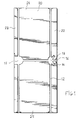
- - la figure 1 représente une porte en bois défoncée pour recevoir le système de blindage décrit ;
- - la figure 2 représente schématiquement ce système de blindage dans ses éléments essentiels ;
- - la figure 3 est une vue éclatée illustrant le montage du système de blindage dans la porte ;
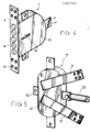
- - la figure 4 et 5 montrent respectivement les deux boîtes de déviation en vue extérieure ;
- - les figures 6,7,8 illustrent la constitution interne de la boîte incorporant une serrure ;
- - les figures 9 et 10 illustrent la constitution interne de l'autre boîte ;
- - et la figure 11 représente une pièce annexe du système.
- - Figure 1 shows a wooden door smashed to receive the armor system described;
- - Figure 2 shows schematically this shielding system in its essential elements;
- - Figure 3 is an exploded view illustrating the mounting of the shielding system in the door;
- - Figure 4 and 5 respectively show the two deflection boxes in external view;
- - Figures 6,7,8 illustrate the internal constitution of the box incorporating a lock;
- - Figures 9 and 10 illustrate the internal constitution of the other box;
- - and Figure 11 shows an annex of the system.
Le système de blindage de porte considéré dans ce mode de réalisation particulier de l'invention, tel qu'il est représenté notamment sur la figure 2, est utilisé pour équiper, sur place, une porte en bois 20 (fig. 1) de type traditionnel. On peut considérer que cette porte, qui est de forme plane rectangulaire, est limitée par deux montants 22 et 23, et par deux traverses 24 et 25, bien que ces quatre éléments puissent être réalisés comme il est représenté sur les figures, d'une seule pièce avec l'âme de la porte remplissant l'espace qu'ils délimitent entre eux. Les deux montants définissent les bords latéraux de la porte, qui sont orientés verticalement dans la position d'utilisation, le montant 22 étant celui qui porte les paumelles (non représentées) par lesquelles la porte est montée pivotante par rapport à un encadrement fixe. Les deux traverses 24 et 25 définissent deux bords transversaux qui sont perpendiculaires aux bords latéraux respectivement en haut et en bas de la porte.The door shielding system considered in this particular embodiment of the invention, as shown in particular in Figure 2, is used to equip, on site, a wooden door 20 (fig. 1) of the type traditional. It can be considered that this door, which is of rectangular planar shape, is limited by two
Comme le montre la figure 1, ainsi que la vue éclatée de la figure 3, la porte 20 présente des défoncements qui sont réalisés par la face arrière de la porte, sans atteindre la face avant, au moment de la mise en place du système de blindage sur une porte existante. Ces défoncements sont destinés à recevoir dans l'épaisseur de la porte les différents éléments qui constituent le système de blindage, avec en particulier des défoncements 15 et 16 pour des boîtes de déviation 1 et 7 et des défoncements tels que 12 pour des barres de liaison 11. Un exemple de dimension pour la profondeur de ces défoncements est de 32 mm dans une porte de 40 mm d'épaisseur.As shown in FIG. 1, as well as the exploded view of FIG. 3, the
Le système de blindage comporte des pênes rétractables tels que 26 qui se répartissent autour de la porte en se plaçant dans l'épaisseur de celle-ci, perpendiculairement à la tranche 27 (fig. 3) de la porte. Ces pênes sont représentés sur la figure 2 dans leur position rétractée, où ils s'effacent à l'intérieur du pourtour de la porte, tandis que sur la figure 3 ils sont représentés dans une position éjectée. Quand la porte est fermée, ils assurent alors son verrouillage en pénétrant dans des gâches qui sont ménagées à cet effet, dans des emplacements correspondants, dans un encadrement fixe entourant la porte qui n'a pas été représenté sur les figures. La commande des différents pênes, pour les rétracter et ouvrir la porte ou pour les éjecter en position de verrouillage de la porte fermée, s'effectue, de manière simultanée, à partir d'une serrure par l'intermédiaire des boîtes de déviation 1 et 7 et des barres de liaison 11.The shielding system comprises retractable bolts such as 26 which are distributed around the door by being placed in the thickness of the latter, perpendicular to the edge 27 (fig. 3) of the door. These bolts are shown in Figure 2 in their retracted position, where they disappear inside the periphery of the door, while in Figure 3 they are shown in an ejected position. When the door is closed, they then ensure its locking by entering strikes which are provided for this purpose, in corresponding locations, in a fixed frame surrounding the door which has not been shown in the figures. The control of the various bolts, to retract them and open the door or to eject them in the locked position of the closed door, is carried out, simultaneously, from a lock via the
Dans le système selon l'invention, la serrure est intégrée dans l'une des boîtes de déviation 1. Il s'agit d'une serrure à george qui apparaît en 28 sur la vue de la figure 4. Dans leurs mécanismes internes, les boîtes de déviation 1 et 7 sont constituées d'une manière qui est en elle-même classique et qui est représentée par les figures 6 et 12. L'essentiel de ces mécanismes réside dans le fait qu'ils constituent des moyens de renvoi de déplacement pour commander des pattes mobiles 6 dépassant à l'extérieur d'un carter 30 (fig. 4) ou 41 (fig. 5) qui enferme les mécanismes internes de chaque boîte. Ces pattes 6 sont chacune perforées d'un orifice 31 (fig. 4) permettant de fixer dessus par boulonnage une extrémité aplatie des barres de liaison, de manière rigide, comme on l'a représenté pour un pêne 32 sur la figure 5. On voit sur la figure 4 que la boîte de déviation 1 intégrant la serrure 28 comporte en outre une série de pênes 33 qui sont rétractables dans le carter 30 de cette boîte et qui sont directement commandés par la serrure, par des mécanismes internes de cette boîte.In the system according to the invention, the lock is integrated in one of the deflection boxes 1. It is a george lock which appears at 28 in the view of FIG. 4. In their internal mechanisms, the
En revenant maintenant sur les figures 2 et 3, on remarque que les deux boîtes de déviation 1 et 7 se placent en des positions opposées près des bords latéraux de la porte dans une partie médiane de celle-ci. Plus exactement la boîte 1 qui comporte la serrure se place dans le défoncement 15 à proximité immédiate du montant 23, du côté ouvrant de la porte, tandis que la boîte 7 se place à l'opposé à proximité immédiate du montant 22 portant les paumelles. Les deux boîtes 1 et 7 sont reliées entre elles par une barre de liaison spéciale qui constitue une tige de transmission de mouvement 34 dans la commande de l'ensemble des pênes. Cette tige 34 est orientée transversalement à la porte dans la partie médiane de celle-ci. Elle est fixée en une extrémité sur la patte mobile 6 de la boîte 1 et en son autre extrémité sur une patte mobile 35 (fig. 5) de la boîte 7. La patte 35 se trouve ainsi déplacée en translation en le même sens que la patte 6, ce qui implique que les mécanismes de renvoi interne de la boîte 7 inversent le mouvement pour que les autres pattes mobiles dépassant de la boîte 7 se déplacent par rapport au centre de la boîte dans le même sens que la patte 6 par rapport au centre de la boîte 1.Returning now to FIGS. 2 and 3, it is noted that the two
En plus de la tige de transmission 34, le système de blindage de l'invention comporte principalement quatre barres de liaison qui portent les références 11,37,38 et 39 sur la figure 2. Chacune est fixée à une extrémité sur une patte mobile de l'une des boîtes 1 et 7 pour servir à transmettre la commande de verrouillage ou déverrouillage à un pêne rétractable qui est en fait constitué par l'extrémité opposée de la barre correspondante. Deux de ces barres soit 11 et 37 sont alignées verticalement et logées dans des défoncements 12 de la porte (fig. 3) ménagés à cet effet parallèlement au montant 22. Elles sont reliées respectivement à deux pattes mobiles du boîtier 7 situées sur l'axe vertical. De la même manière les deux autres barres 38 et 39 se placent orientées verticalement près du montant 23 et elles sont fixées à des pattes mobiles de la boîte 1. On comprend donc que les différents pênes correspondant à ces quatre barres de liaison sont situés en des positions opposées sur les bords transversaux de la porte et qu'ils sont rétractables et éjectables par la tranche des traverses 20 et 25.In addition to the
Comme la boîte de déviation 7 comporte en outre un pêne 32 déjà mentionné, qui est orienté dans le sens transversal de la porte pour verrouiller celle-ci sur le montant vertical de l'encadrement d'huisserie, on comprend aussi que chacune des boîtes 1 et 7 comporte trois pattes mobiles orientées à angle droit les unes des autres.As the
Une fois mises en place dans leurs logements respectifs constitués par les défoncements 15 et 16, les boîtes de déviation 1 et 7 sont fixées sur la porte pour y être solidement maintenues. A cet effet la boîte 1 incorporant la serrure comporte une ferrure 2 traversée par les pênes 33 (fig. 4), ferrure qui s'intègre dans un défoncement peu profond (par exemple 2 mm) pratiqué à cet effet dans la tranche de la porte le long de son bord latéral. Des trous 40 de cette ferrure facilitent sa fixation par vissage sur la tranche de la porte.Once placed in their respective housings formed by the
La boîte de déviation 7 est fixée de manière différente en liaison avec le fait qu'elle n'affleure pas sur la tranche de la porte autrement que par le pêne 32. Son mode de fixation est conçu spécialement pour encaisser sans risque tous les efforts qui peuvent s'exercer sur la boîte. Il implique deux pattes fixes 9 et 10 qui sont soudées sur le dessus du carter 41 de cette boîte 7 et qui, au fait près qu'elles ne passent pas par le centre de la boîte, dépassent du carter 41 dans une orientation sensiblement suivant les bissectrices des angles que forment les trois pattes mobiles de commande des pênes. Dans la porte 20 ces deux pattes fixes 9 et 10 se placent dans des défoncements 13 et 14 peu profonds ménagés de manière correspondante comme il apparaît sur les figures 1 et 3.The
L'ensemble des éléments du système de blindage tels qu'ils viennent d'être décrits, quand ils sont en place dans les défoncements de la porte 20, sont rendus invisibles et inaccessibles par une plaque de protection 17, constituée par une plaque de tôle métallique, qui recouvre l'ensemble de la face arrière de la porte et qui est maintenue appliquée contre celle-ci par un cadre 18, réalisé en double cornières et fixé sur la tranche de la porte.All the elements of the shielding system as they have just been described, when they are in place in the knockouts of the
On explicitera maintenant d'autres particularités du système de blindage décrit qui facilitent sont adaptation sur toute porte existante, quelles que soient ses dimensions, ainsi que sa mise en oeuvre lors de son montage sur la porte.We will now explain other particularities of the shielding system described which facilitate its adaptation to any existing door, whatever its dimensions, as well as its implementation when it is mounted on the door.
Ainsi chacune des différentes barres de liaison 11,37,38 et 39 de même que la tige de transmission transversale 34 sont réalisées de manière télescopique afin de permettre leur réglage en longueur en fonction des dimensions de la porte. Chacune, telle que la barre 11 (fig. 2) comporte donc en fait deux tubes 2 et 4 qui coulissent l'un dans l'autre. Quand la longueur est réglée par leur déplacement relatif, ils sont fixés rigidement dans leur position relative par l'intermédiaire d'un anneau 5 formé à l'extrémité du tube le plus large 4 que l'on fixe par rivetage sur le tube plus étroit 3.Thus each of the different connecting
Par ailleurs, on remarque sur la figure 3, qu'il est prévu des plaquettes métalliques 45 destinées à renforcer le système une fois monté dans la porte 20. Leur rôle est analogue à celui de la ferrure 2 dans le guidage des déplacements de chacun des pênes autres que les pênes 33. Chaque plaquette 45 comporte donc un orifice central pour le passage du pêne correspondant et elle se fixe sur la tranche de la porte perpendiculairement à ce pêne. La fixation est assurée par vissage et des défoncements peu profonds 46 sont ménagés dans la porte 20 pour la recevoir.Furthermore, it can be seen in FIG. 3 that there are provided metal plates 45 intended to reinforce the system once mounted in the
Dans un mode de réalisation préféré de l'invention qui n'a pas été illustré sur les figures, on conserve sous sa forme plane celle de ces plaquettes, soit la plaquette 47, qui coopère avec le pêne 32 commandé directement par la boîte de déviation 7, alors que l'on remplace les quatre autres plaquettes 45, situées sur les traverses de la porte par des plaquettes en équerre, de forme appropriée pour recouvrir l'angle correspondant entre montant et traverse. On peut aussi consolider l'encadrement d'huisserie de manière similaire, au moyen d'autres plaquettes, perforées pour permettre la pénétration de chaque pêne.In a preferred embodiment of the invention which has not been illustrated in the figures, that of these plates, that is the plate 47, which cooperates with the
Lors du montage du système de blindage sur une porte, on commence par pratiquer les défoncements nécessaires au gabarit des boîtes de déviation et des différentes barres. On fixe ensuite les boîtes de déviation et les différents éléments qui viennent sur la tranche de la porte. Bien entendu on aura également pratiqué un perçage de la porte jusqu'à sa face avant pour permettre le passage d'une clé de commande de la serrure pénétrant à travers le carter 30 par une lumière 50 (fig. 4). On engage ensuite les barres de liaison à travers les orifices des plaquettes 45 pour les fixer sur les pattes mobiles qui leur sont affectées, après avoir réglé leur longueur. On remarquera ici qu'il reste toujours possible de démonter ultérieurement le système pour le replacer sur une autre porte, en cas de déménagement du propriétaire par exemple.When mounting the shielding system on a door, we start by making the necessary knockouts for the size of the deflection boxes and the various bars. The deflection boxes and the various elements that come on the edge of the door are then fixed. Of course, the door will also have been drilled up to its front face to allow the passage of a key for controlling the lock penetrating through the
Enfin il est avantageux d'associer au système de blindage décrit une pièce annexe 55 représentée sur la figure qui se pose de manière provisoire sur la tranche de la porte en correspondance avec chacun des pênes et qui comporte une pointe extérieure pour poinçonner l'endroit où devront être pratiquées les gâches dans l'encadrement d'huisserie. Cette pièce 55 est constituée par une barrette métallique conformée en deux parties droites décalées, dont l'une 56 porte, perpendiculairement à son plan, un pion 57 à pointe acérée 58. Pour l'utiliser on engage le pion 57 dans un trou central prévu à cet effet dans le pêne 26, la partie 56 de la pièce reposant sur la tranche de la porte 20, puis porte fermée, on actionne partiellement le système d'éjection des pênes, de sorte que l'on pousse ainsi la pointe 58 vers l'extérieur pour assurer le poinçonnage. L'autre partie 59 de la pièce 55 constitue un levier facilitant le retrait de cette pièce après le poinçonnage.Finally, it is advantageous to associate with the shielding system described an
Jusqu'ici, il n'a pas semblé utile de décrire les mécanismes internes des deux boîtes de déviation, qui sont en eux-mêmes classiques. On pourra cependant se référer aux figures 6 à 10 pour comprendre leur fonctionnement.So far, it has not seemed useful to describe the internal mechanisms of the two deflection boxes, which are in themselves classic. We can however refer to Figures 6 to 10 to understand their operation.
On y voit en particulier qu'en plus de quatre pênes rétractables 33, la boîte 1 comporte un pêne 51 (fig. 6) actionné par une targette 52 par un premier demi-tour de clé dans la serrure. La même clé commande ensuite les pênes 33, solidaires d'une pièce d'entraînement 53 (fig. 7). Les trois pattes mobiles 61,62,63 sont solidaires de trois pièces 64,65,66 (fig. 8) qui s'entraînent mutuellement en même temps que la pièce 53 grâce à des pions tels que 67, coulissant dans des lumières 68.We see in particular that in addition to four
Dans la boîte 7 (fig. 9 et 10) les pattes mobiles 69,70 commandant les pênes de l'axe vertical sont formées dans des pièces en angle 72 et 73 qui par un jeu de pions 74 et lumière 75 sont entraînées par la translation d'une pièce horizontale 76 portant en ligne la troisième patte 71 sur laquelle se fixe le pêne 33 et la patte 35 sur laquelle se fixe la tige de transmission liée à la boîte 1.In the box 7 (fig. 9 and 10) the movable legs 69.70 controlling the bolts of the vertical axis are formed in
D'autre part, dans une variante de réalisation de l'invention qui sera souvent préférée en pratique, le système de blindage tel qu'il a été décrit est tout autant adapté à un montage sur une porte à alvéoles dans laquelle seuls les montants et traverses sont en bois plein. Dans ce cas, il n'est pas nécessaire de pratiquer en totalité les défoncements décrits ci-dessus. Les boîtes de déviation et les barres de liaison peuvent être introduites dans la porte à travers des ouvertures ménagées dans le montant 22 et dans les traverses après avoir dégagé une place suffisante à l'intérieur de la porte par tassement de la matière constituant les alvéoles. A part des défoncements pratiqués sur la tranche de la porte, les défoncements réalisés par la face arrière se limitent à ceux qui reçoivent les pattes fixes 13 et 14 et à des trous d'accès aux différents points de fixation des barres de liaison sur les pattes mobiles des deux boîtes de déviation.On the other hand, in an alternative embodiment of the invention which will often be preferred in practice, the shielding system as it has been described is just as suitable for mounting on a cell door in which only the uprights and sleepers are solid wood. In this case, it is not necessary to fully practice the rams described above. The deflection boxes and the connecting bars can be introduced into the door through openings made in the
Naturellement, l'invention n'est en rien limitée par les particularités qui ont été spécifiées dans ce qui précède ou par les détails du mode de réalisation particulier choisi pour illustrer l'invention. Toutes sortes de variantes peuvent être apportées à la réalisation particulière qui a été décrite à titre d'exemple et à ses éléments constitutifs sans sortir pour autant du cadre de l'invention. Cette dernière englobe ainsi tous les moyens constituant des équivalents techniques des moyens décrits ainsi que leurs combinaisons.Naturally, the invention is in no way limited by the features which have been specified in the foregoing or by the details of the particular embodiment chosen to illustrate the invention. All kinds of variants can be made to the particular embodiment which has been described by way of example and to its constituent elements without departing from the scope of the invention. The latter thus includes all the means constituting technical equivalents of the means described as well as their combinations.
Claims (8)
Applications Claiming Priority (2)
| Application Number | Priority Date | Filing Date | Title |
|---|---|---|---|
| FR8705249 | 1987-04-14 | ||
| FR8705249A FR2614062B1 (en) | 1987-04-14 | 1987-04-14 | DEVICE AND METHOD FOR MOUNTING A SECURITY DOOR HAVING MANY ANCHOR POINTS |
Publications (1)
| Publication Number | Publication Date |
|---|---|
| EP0287466A1 true EP0287466A1 (en) | 1988-10-19 |
Family
ID=9350081
Family Applications (1)
| Application Number | Title | Priority Date | Filing Date |
|---|---|---|---|
| EP88400897A Withdrawn EP0287466A1 (en) | 1987-04-14 | 1988-04-14 | Armoured door |
Country Status (2)
| Country | Link |
|---|---|
| EP (1) | EP0287466A1 (en) |
| FR (1) | FR2614062B1 (en) |
Cited By (6)
| Publication number | Priority date | Publication date | Assignee | Title |
|---|---|---|---|---|
| DE8900484U1 (en) * | 1989-01-18 | 1989-03-02 | Werning, Hans-Robert, 4800 Bielefeld, De | |
| FR2639991A1 (en) * | 1988-12-06 | 1990-06-08 | Valente Massimo | DOOR SHIELDING SYSTEM AND RELATED SECURITY LOCK DEVICE |
| DE4128213A1 (en) * | 1991-08-26 | 1993-03-04 | Jeche Regine | SECURITY DOOR AND SECURITY DEVICE FOR INSTALLATION IN A DOOR |
| WO1996027725A1 (en) * | 1995-03-07 | 1996-09-12 | Rittal-Werk Rudolf Loh Gmbh & Co. Kg | Door locking device with several closing rods |
| FR2862691A1 (en) * | 2003-11-25 | 2005-05-27 | Tallec Jean Michel Le | Multiple-opening e.g. door, securing system for use in building, has bolts and strikes that are adapted so that bolts penetrate into strikes situated at immediate proximity to rotation axes with respect to frame |
| FR2961247A1 (en) * | 2010-06-11 | 2011-12-16 | Henri Eymar | Shielded door for use in dwelling, has metal frames fixed on sides of leaf, where strike plates are arranged in frames, side bolts inserted inside strike plates during locking, and shielding plate fixed on inner face of leaf |
Citations (6)
| Publication number | Priority date | Publication date | Assignee | Title |
|---|---|---|---|---|
| FR357179A (en) * | 1905-08-22 | 1905-12-20 | Joseph Girod | Safety locking device for doors |
| FR993509A (en) * | 1949-06-22 | 1951-11-02 | Moreau Freres Ets | Double-leaf door locking device |
| FR2355981A1 (en) * | 1976-06-21 | 1978-01-20 | Bahry Abraham | CLOSING DEVICE FOR DOORS AND SIMILAR |
| FR2376279A1 (en) * | 1976-12-30 | 1978-07-28 | Herrenbrandt Michel | Security lock with hinge reinforcements - has three sliding bolts each securing different door edge and converging on plate rotated by cam |
| FR2428724A1 (en) * | 1978-06-16 | 1980-01-11 | Ferco Int Usine Ferrures | Locking guide plate for door or window opening - has right angle section and star-shaped biting studs to prevent slip |
| GB2133456A (en) * | 1983-01-19 | 1984-07-25 | Jgr Enterprises Inc | Security door |
-
1987
- 1987-04-14 FR FR8705249A patent/FR2614062B1/en not_active Expired - Fee Related
-
1988
- 1988-04-14 EP EP88400897A patent/EP0287466A1/en not_active Withdrawn
Patent Citations (6)
| Publication number | Priority date | Publication date | Assignee | Title |
|---|---|---|---|---|
| FR357179A (en) * | 1905-08-22 | 1905-12-20 | Joseph Girod | Safety locking device for doors |
| FR993509A (en) * | 1949-06-22 | 1951-11-02 | Moreau Freres Ets | Double-leaf door locking device |
| FR2355981A1 (en) * | 1976-06-21 | 1978-01-20 | Bahry Abraham | CLOSING DEVICE FOR DOORS AND SIMILAR |
| FR2376279A1 (en) * | 1976-12-30 | 1978-07-28 | Herrenbrandt Michel | Security lock with hinge reinforcements - has three sliding bolts each securing different door edge and converging on plate rotated by cam |
| FR2428724A1 (en) * | 1978-06-16 | 1980-01-11 | Ferco Int Usine Ferrures | Locking guide plate for door or window opening - has right angle section and star-shaped biting studs to prevent slip |
| GB2133456A (en) * | 1983-01-19 | 1984-07-25 | Jgr Enterprises Inc | Security door |
Cited By (8)
| Publication number | Priority date | Publication date | Assignee | Title |
|---|---|---|---|---|
| FR2639991A1 (en) * | 1988-12-06 | 1990-06-08 | Valente Massimo | DOOR SHIELDING SYSTEM AND RELATED SECURITY LOCK DEVICE |
| EP0373068A1 (en) * | 1988-12-06 | 1990-06-13 | Massimo Valente | Door armouring system |
| DE8900484U1 (en) * | 1989-01-18 | 1989-03-02 | Werning, Hans-Robert, 4800 Bielefeld, De | |
| DE4128213A1 (en) * | 1991-08-26 | 1993-03-04 | Jeche Regine | SECURITY DOOR AND SECURITY DEVICE FOR INSTALLATION IN A DOOR |
| WO1996027725A1 (en) * | 1995-03-07 | 1996-09-12 | Rittal-Werk Rudolf Loh Gmbh & Co. Kg | Door locking device with several closing rods |
| US6035674A (en) * | 1995-03-07 | 2000-03-14 | Rittal-Werk Rudolf Loh Gmbh | Door locking device with several closing rods |
| FR2862691A1 (en) * | 2003-11-25 | 2005-05-27 | Tallec Jean Michel Le | Multiple-opening e.g. door, securing system for use in building, has bolts and strikes that are adapted so that bolts penetrate into strikes situated at immediate proximity to rotation axes with respect to frame |
| FR2961247A1 (en) * | 2010-06-11 | 2011-12-16 | Henri Eymar | Shielded door for use in dwelling, has metal frames fixed on sides of leaf, where strike plates are arranged in frames, side bolts inserted inside strike plates during locking, and shielding plate fixed on inner face of leaf |
Also Published As
| Publication number | Publication date |
|---|---|
| FR2614062A1 (en) | 1988-10-21 |
| FR2614062B1 (en) | 1995-06-23 |
Similar Documents
| Publication | Publication Date | Title |
|---|---|---|
| EP1796510B1 (en) | Modular storage assembly | |
| EP0182731B1 (en) | Suspended-storage device with individual rocking juxtaposed boxes | |
| EP0287466A1 (en) | Armoured door | |
| EP1748525B1 (en) | Corner post for electrical cabinet and cabinet equipped therewith | |
| CH633605A5 (en) | LOCKING DEVICE FOR A DOOR. | |
| FR2814721A1 (en) | Palletized crate has uprights and mesh walls which fold down on to base, each upright having locking pin attached to slide inside it which cooperates with locking plate attached to base which is released by latch mounted on wall | |
| EP1580356B1 (en) | Device for the protection of a door cylinder lock | |
| WO2010076398A1 (en) | Improved device for locking and unlocking a door | |
| EP0385875A1 (en) | Set of letter boxes, with means for complete opening | |
| FR2639991A1 (en) | DOOR SHIELDING SYSTEM AND RELATED SECURITY LOCK DEVICE | |
| FR2861125A1 (en) | SECURITY PORTILLON | |
| FR2697813A1 (en) | Letter box battery - comprises individual pigeonholes, each with its door, enclosed by collective door | |
| EP0557183B1 (en) | Multipoint lock with secondary bolts being operable independently from the main bolt | |
| FR2681369A1 (en) | Security device for doors, windows and the like | |
| FR2587134A1 (en) | Cash compartment in particular for coin-operated apparatuses such as public telephones | |
| FR3080881A1 (en) | LOCKING SYSTEM WITH MECHANICAL LOCKING | |
| EP0898916A1 (en) | Central locking device for multi-unit letter-boxes | |
| FR2639992A2 (en) | Tilt and swing window with three methods of opening and two leaves | |
| EP0438946B1 (en) | Security deposit apparatus comprising an access box connected to a safe | |
| EP1160401B1 (en) | Visible lock for a wing | |
| FR2788547A3 (en) | Lock and bolt assembly for electrical junction box assemblies, comprises an automatically latching system affected when the door is shut | |
| FR2558877A1 (en) | Improvements to sheetings for pouring concurrent walls as one unit | |
| FR2702795A1 (en) | Mechanism for closing the door of a safe | |
| EP3530851A1 (en) | Locking system for a sectional door with lateral movement | |
| CA1283687C (en) | Aerial stowage device having individual side-by-side tilting bins |
Legal Events
| Date | Code | Title | Description |
|---|---|---|---|
| PUAI | Public reference made under article 153(3) epc to a published international application that has entered the european phase |
Free format text: ORIGINAL CODE: 0009012 |
|
| AK | Designated contracting states |
Kind code of ref document: A1 Designated state(s): AT BE CH DE ES FR GB GR IT LI LU NL SE |
|
| 17P | Request for examination filed |
Effective date: 19881210 |
|
| 17Q | First examination report despatched |
Effective date: 19891107 |
|
| STAA | Information on the status of an ep patent application or granted ep patent |
Free format text: STATUS: THE APPLICATION IS DEEMED TO BE WITHDRAWN |
|
| 18D | Application deemed to be withdrawn |
Effective date: 19900518 |