EP0287466A1 - Türpanzerung - Google Patents
Türpanzerung Download PDFInfo
- Publication number
- EP0287466A1 EP0287466A1 EP88400897A EP88400897A EP0287466A1 EP 0287466 A1 EP0287466 A1 EP 0287466A1 EP 88400897 A EP88400897 A EP 88400897A EP 88400897 A EP88400897 A EP 88400897A EP 0287466 A1 EP0287466 A1 EP 0287466A1
- Authority
- EP
- European Patent Office
- Prior art keywords
- door
- bolts
- boxes
- shielding system
- box
- Prior art date
- Legal status (The legal status is an assumption and is not a legal conclusion. Google has not performed a legal analysis and makes no representation as to the accuracy of the status listed.)
- Withdrawn
Links
Images


Classifications
-
- E—FIXED CONSTRUCTIONS
- E05—LOCKS; KEYS; WINDOW OR DOOR FITTINGS; SAFES
- E05C—BOLTS OR FASTENING DEVICES FOR WINGS, SPECIALLY FOR DOORS OR WINDOWS
- E05C9/00—Arrangements of simultaneously actuated bolts or other securing devices at well-separated positions on the same wing
- E05C9/06—Arrangements of simultaneously actuated bolts or other securing devices at well-separated positions on the same wing with three or more sliding bars
-
- E—FIXED CONSTRUCTIONS
- E05—LOCKS; KEYS; WINDOW OR DOOR FITTINGS; SAFES
- E05C—BOLTS OR FASTENING DEVICES FOR WINGS, SPECIALLY FOR DOORS OR WINDOWS
- E05C9/00—Arrangements of simultaneously actuated bolts or other securing devices at well-separated positions on the same wing
- E05C9/10—Actuating mechanisms for bars
- E05C9/14—Actuating mechanisms for bars with pins engaging slots
Definitions
- the present invention relates to a door shielding system with several locking anchor points which is designed in particular to allow its easy adaptation to a traditional wooden door and to improve the inviolability.
- door used here extends to any type of frame.
- a door shielding system which can be made invisible by a protective plate and which comprises a plurality of retractable bolts for locking the door by penetration into strikes made for this purpose in a door frame, as well as a device for simultaneously controlling said bolts from a lock with an external control member by means of a linkage.
- the linkage comprises individual bars for moving the different bolts which are actuated through deflection boxes making it possible to move in two opposite directions two bolts located on the edge of two opposite parallel edges of the door possibly at the same time that a third bolt in a perpendicular direction on a third edge of the door.
- the lock and deflection boxes which are fully described in their mechanism and operation, are all arranged in the central part of the door.
- the subject of the invention is a door shielding system to be incorporated into a flat door limited by two opposite uprights defining lateral edges and two opposite cross-pieces defining transverse edges substantially perpendicular to said uprights, said system comprising a plurality of retractable bolts distributed around the door which are integral with connecting bars of said bolts with deflection boxes comprising displacement return means for controlling from a lock the simultaneous ejection of said bolts by the edge of the door in a position of locking where they enter a fixed frame of the door, characterized in that it comprises two deflection boxes arranged in a middle part of the door in the immediate vicinity respectively of the two uprights, each having movable lugs for fixing said connecting bars towards at least one bolt located on the corresponding lateral edge and towards two bolts situated respectively on each of said opposite transverse edges and in that said lock is integrated in a first of said deflection boxes while a second of said boxes has two fixing lugs in the corresponding upright which are oriented substantially along the bisectors of said connecting bars to
- said first box that which integrates the lock, is fixed in the thickness of the door by a fitting screwed in its edge.
- the connecting bars with the bolts which are preferably formed directly by the end of each bar, are advantageously guided in a similar manner by passing through plates fixed on the edge Door.
- said door is made of wood and it has knockouts on one side to receive in its thickness said boxes and said bars, and the shielding system comprises a protective plate maintained applied on one side rear of the door by an angle frame fixed on the edge of the door.
- the shielding system furthermore comprises retractable bolts situated on the lateral edges of the door opposite each of said boxes respectively and controlled directly from the corresponding box.
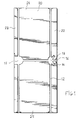
- the door shielding system considered in this particular embodiment of the invention is used to equip, on site, a wooden door 20 (fig. 1) of the type traditional. It can be considered that this door, which is of rectangular planar shape, is limited by two uprights 22 and 23, and by two crosspieces 24 and 25, although these four elements can be produced as shown in the figures, of a single piece with the soul of the door filling the space they delimit between them.
- the two uprights define the side edges of the door, which are oriented vertically in the position of use, the upright 22 being that which carries the hinges (not shown) by which the door is pivotally mounted relative to a fixed frame.
- the two crosspieces 24 and 25 define two transverse edges which are perpendicular to the lateral edges respectively at the top and at the bottom of the door.
- the door 20 has knockouts which are produced by the rear face of the door, without reaching the front face, when the installation system is in place. shielding on an existing door. These knockouts are intended to receive in the thickness of the door the various elements which constitute the shielding system, with in particular knockouts 15 and 16 for deflection boxes 1 and 7 and knockouts such as 12 for connecting bars 11.
- knockouts 15 and 16 for deflection boxes 1 and 7 and knockouts such as 12 for connecting bars 11.
- An example of a dimension for the depth of these knockouts is 32 mm in a door 40 mm thick.
- the shielding system comprises retractable bolts such as 26 which are distributed around the door by being placed in the thickness of the latter, perpendicular to the edge 27 (fig. 3) of the door. These bolts are shown in Figure 2 in their retracted position, where they disappear inside the periphery of the door, while in Figure 3 they are shown in an ejected position. When the door is closed, they then ensure its locking by entering strikes which are provided for this purpose, in corresponding locations, in a fixed frame surrounding the door which has not been shown in the figures.
- the control of the various bolts, to retract them and open the door or to eject them in the locked position of the closed door is carried out, simultaneously, from a lock via the deflection boxes 1 and 7 and connecting bars 11.
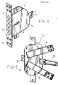
- the lock is integrated in one of the deflection boxes 1. It is a george lock which appears at 28 in the view of FIG. 4.
- the deflection boxes 1 and 7 are constituted in a manner which is in itself conventional and which is represented by FIGS. 6 and 12.
- the essential of these mechanisms resides in the fact that they constitute displacement return means to control movable legs 6 projecting outside a casing 30 (fig. 4) or 41 (fig. 5) which encloses the internal mechanisms of each box.
- These tabs 6 are each perforated with an orifice 31 (FIG. 4) allowing it to be fixed by bolting a flattened end of the connection bars, rigidly, as has been shown for a bolt 32 in FIG. see in Figure 4 that the deflection box 1 incorporating the lock 28 further comprises a series of bolts 33 which are retractable in the housing 30 of this box and which are directly controlled by the lock, by internal mechanisms of this box.
- the two deflection boxes 1 and 7 are placed in opposite positions near the lateral edges of the door in a middle part of the latter. More exactly the box 1 which comprises the lock is placed in the knockout 15 in the immediate vicinity of the upright 23, on the opening side of the door, while the box 7 is placed in the immediate vicinity of the upright 22 carrying the hinges.
- the two boxes 1 and 7 are interconnected by a special connecting bar which constitutes a movement transmission rod 34 in the control of the set of bolts.
- This rod 34 is oriented transversely to the door in the middle part of the latter. It is fixed at one end to the movable tab 6 of the box 1 and at its other end to a movable tab 35 (fig. 5) of the box 7.
- the tab 35 is thus moved in translation in the same direction as the leg 6, which implies that the internal return mechanisms of the box 7 reverse the movement so that the other movable legs protruding from the box 7 move relative to the center of the box in the same direction as the leg 6 relative to the center of box 1.
- the shielding system of the invention mainly comprises four connecting bars which bear the references 11,37,38 and 39 in FIG. 2. Each is fixed at one end to a movable leg of one of the boxes 1 and 7 to serve to transmit the locking or unlocking command to a retractable bolt which is in fact constituted by the opposite end of the corresponding bar.
- Two of these bars, ie 11 and 37, are aligned vertically and housed in knockouts 12 of the door (fig. 3) formed for this purpose parallel to the upright 22. They are connected respectively to two movable legs of the housing 7 located on the axis vertical.
- the other two bars 38 and 39 are placed vertically oriented near the upright 23 and they are fixed to movable legs of the box 1. It is therefore understood that the different bolts corresponding to these four connecting bars are located in opposite positions on the transverse edges of the door and they are retractable and ejectable by the slice of sleepers 20 and 25.
- each of the boxes 1 and 7 has three movable legs oriented at right angles to each other.
- the deflection boxes 1 and 7 are fixed on the door to be securely held there.
- the box 1 incorporating the lock comprises a fitting 2 crossed by the bolts 33 (fig. 4), fitting which is integrated in a shallow knockout (for example 2 mm) made for this purpose in the edge of the door along its side edge. Holes 40 of this fitting facilitate its fixing by screwing on the edge of the door.
- the deflection box 7 is fixed differently in connection with the fact that it does not surface on the edge of the door other than by the bolt 32. Its method of fixing is specially designed to safely absorb all the efforts which can be exercised on the box. It involves two fixed tabs 9 and 10 which are welded to the top of the casing 41 of this box 7 and which, apart from the fact that they do not pass through the center of the box, protrude from the casing 41 in an orientation substantially according to the bisectors of the angles formed by the three movable lugs for controlling the bolts. In the door 20, these two fixed legs 9 and 10 are placed in shallow recesses 13 and 14 formed in a corresponding manner as it appears in FIGS. 1 and 3.
- a protective plate 17 consisting of a metal sheet plate, which covers the whole of the rear face of the door and which is held pressed against the latter by a frame 18, produced in double angles and fixed on the edge of the door.
- each of the different connecting bars 11, 37, 38 and 39 as well as the transverse transmission rod 34 are made telescopically so as to allow their length adjustment as a function of the dimensions of the door.
- Each, such as the bar 11 therefore in fact comprises two tubes 2 and 4 which slide one inside the other. When the length is adjusted by their relative displacement, they are rigidly fixed in their relative position by means of a ring 5 formed at the end of the widest tube 4 which is fixed by riveting to the narrower tube 3.
- metal plates 45 intended to reinforce the system once mounted in the door 20. Their role is similar to that of the fitting 2 in guiding the movements of each of the bolts other than the bolts 33.
- Each plate 45 therefore has a central orifice for the passage of the corresponding bolt and it is fixed on the edge of the door perpendicular to this bolt. The fixing is ensured by screwing and shallow knockouts 46 are provided in the door 20 to receive it.
- an additional part 55 shown in the figure which is provisionally placed on the edge of the door in correspondence with each of the bolts and which has an external point for punching the place where the strikes must be made in the frame frame.
- This part 55 is constituted by a metal bar shaped into two offset offset parts, one of which 56 carries, perpendicular to its plane, a pin 57 with sharp point 58. To use it, the pin 57 is engaged in a central hole provided for this purpose in the bolt 26, the part 56 of the part resting on the edge of the door 20, then the door closed, the bolt ejection system is partially actuated, so that the point 58 is thus pushed towards the outside to ensure punching.
- the other part 59 of part 55 constitutes a lever facilitating the removal of this part after punching.
- the box 1 includes a bolt 51 (fig. 6) actuated by a bolt 52 by a first turn of the key in the lock. The same key then controls the bolts 33, integral with a drive part 53 (fig. 7).
- the three movable legs 61,62,63 are integral with three parts 64,65,66 (fig. 8) which drive each other at the same time as the part 53 thanks to pins such as 67, sliding in slots 68.
- the movable legs 69.70 controlling the bolts of the vertical axis are formed in angled parts 72 and 73 which by a set of pins 74 and light 75 are driven by the translation a horizontal piece 76 carrying in line the third tab 71 on which the bolt 33 is fixed and the tab 35 on which the transmission rod linked to the box 1 is fixed.
- the shielding system as it has been described is just as suitable for mounting on a cell door in which only the uprights and sleepers are solid wood.
- the deflection boxes and the connecting bars can be introduced into the door through openings made in the upright 22 and in the crosspieces after having cleared a sufficient space inside the door by packing the material constituting the cells.
- the knockouts made by the rear face are limited to those which receive the fixed tabs 13 and 14 and to access holes at the different fixing points of the connecting bars on the movable legs of the two deflection boxes.
Landscapes
- Engineering & Computer Science (AREA)
- Mechanical Engineering (AREA)
- Specific Sealing Or Ventilating Devices For Doors And Windows (AREA)
- Special Wing (AREA)
Applications Claiming Priority (2)
| Application Number | Priority Date | Filing Date | Title |
|---|---|---|---|
| FR8705249A FR2614062B1 (fr) | 1987-04-14 | 1987-04-14 | Dispositif et procede de montage d'une porte de securite ayant de nombreux points d'ancrages |
| FR8705249 | 1987-04-14 |
Publications (1)
| Publication Number | Publication Date |
|---|---|
| EP0287466A1 true EP0287466A1 (de) | 1988-10-19 |
Family
ID=9350081
Family Applications (1)
| Application Number | Title | Priority Date | Filing Date |
|---|---|---|---|
| EP88400897A Withdrawn EP0287466A1 (de) | 1987-04-14 | 1988-04-14 | Türpanzerung |
Country Status (2)
| Country | Link |
|---|---|
| EP (1) | EP0287466A1 (de) |
| FR (1) | FR2614062B1 (de) |
Cited By (6)
| Publication number | Priority date | Publication date | Assignee | Title |
|---|---|---|---|---|
| DE8900484U1 (de) * | 1989-01-18 | 1989-03-02 | Werning, Hans-Robert, 4800 Bielefeld, De | |
| FR2639991A1 (fr) * | 1988-12-06 | 1990-06-08 | Valente Massimo | Systeme de blindage de porte et dispositif de serrure de securite s'y rapportant |
| DE4128213A1 (de) * | 1991-08-26 | 1993-03-04 | Jeche Regine | Sicherheitstuer und sicherheitsvorrichtung zum einbau in eine tuer |
| WO1996027725A1 (de) * | 1995-03-07 | 1996-09-12 | Rittal-Werk Rudolf Loh Gmbh & Co. Kg | Türverschluss mit mehreren schliessstangen |
| FR2862691A1 (fr) * | 2003-11-25 | 2005-05-27 | Tallec Jean Michel Le | Systeme de fermeture et procede de securisation d'ouvrant(s) |
| FR2961247A1 (fr) * | 2010-06-11 | 2011-12-16 | Henri Eymar | Porte blindee |
Citations (6)
| Publication number | Priority date | Publication date | Assignee | Title |
|---|---|---|---|---|
| FR357179A (fr) * | 1905-08-22 | 1905-12-20 | Joseph Girod | Dispositif de fermeture de sureté pour portes |
| FR993509A (fr) * | 1949-06-22 | 1951-11-02 | Moreau Freres Ets | Dispositif de verrouillage des portes à double battant |
| FR2355981A1 (fr) * | 1976-06-21 | 1978-01-20 | Bahry Abraham | Dispositif de fermeture pour portes et analogues |
| FR2376279A1 (fr) * | 1976-12-30 | 1978-07-28 | Herrenbrandt Michel | Mecanisme de securite |
| FR2428724A1 (fr) * | 1978-06-16 | 1980-01-11 | Ferco Int Usine Ferrures | Dispositif de fixation et de guidage pour extremite de cremone |
| GB2133456A (en) * | 1983-01-19 | 1984-07-25 | Jgr Enterprises Inc | Security door |
-
1987
- 1987-04-14 FR FR8705249A patent/FR2614062B1/fr not_active Expired - Fee Related
-
1988
- 1988-04-14 EP EP88400897A patent/EP0287466A1/de not_active Withdrawn
Patent Citations (6)
| Publication number | Priority date | Publication date | Assignee | Title |
|---|---|---|---|---|
| FR357179A (fr) * | 1905-08-22 | 1905-12-20 | Joseph Girod | Dispositif de fermeture de sureté pour portes |
| FR993509A (fr) * | 1949-06-22 | 1951-11-02 | Moreau Freres Ets | Dispositif de verrouillage des portes à double battant |
| FR2355981A1 (fr) * | 1976-06-21 | 1978-01-20 | Bahry Abraham | Dispositif de fermeture pour portes et analogues |
| FR2376279A1 (fr) * | 1976-12-30 | 1978-07-28 | Herrenbrandt Michel | Mecanisme de securite |
| FR2428724A1 (fr) * | 1978-06-16 | 1980-01-11 | Ferco Int Usine Ferrures | Dispositif de fixation et de guidage pour extremite de cremone |
| GB2133456A (en) * | 1983-01-19 | 1984-07-25 | Jgr Enterprises Inc | Security door |
Cited By (8)
| Publication number | Priority date | Publication date | Assignee | Title |
|---|---|---|---|---|
| FR2639991A1 (fr) * | 1988-12-06 | 1990-06-08 | Valente Massimo | Systeme de blindage de porte et dispositif de serrure de securite s'y rapportant |
| EP0373068A1 (de) * | 1988-12-06 | 1990-06-13 | Massimo Valente | Türpanzerungssystem |
| DE8900484U1 (de) * | 1989-01-18 | 1989-03-02 | Werning, Hans-Robert, 4800 Bielefeld, De | |
| DE4128213A1 (de) * | 1991-08-26 | 1993-03-04 | Jeche Regine | Sicherheitstuer und sicherheitsvorrichtung zum einbau in eine tuer |
| WO1996027725A1 (de) * | 1995-03-07 | 1996-09-12 | Rittal-Werk Rudolf Loh Gmbh & Co. Kg | Türverschluss mit mehreren schliessstangen |
| US6035674A (en) * | 1995-03-07 | 2000-03-14 | Rittal-Werk Rudolf Loh Gmbh | Door locking device with several closing rods |
| FR2862691A1 (fr) * | 2003-11-25 | 2005-05-27 | Tallec Jean Michel Le | Systeme de fermeture et procede de securisation d'ouvrant(s) |
| FR2961247A1 (fr) * | 2010-06-11 | 2011-12-16 | Henri Eymar | Porte blindee |
Also Published As
| Publication number | Publication date |
|---|---|
| FR2614062A1 (fr) | 1988-10-21 |
| FR2614062B1 (fr) | 1995-06-23 |
Similar Documents
| Publication | Publication Date | Title |
|---|---|---|
| EP1796510B1 (de) | Modulare lageranordnung | |
| EP0182731B1 (de) | Hängevorrichtung zur Anordnung von individuellen kippbaren und nebeneinanderangeordneten Behältern | |
| EP0287466A1 (de) | Türpanzerung | |
| EP1748525B1 (de) | Eckpfosten für Schaltschrank und damit ausgerüsteter Schaltschrank | |
| CH633605A5 (fr) | Dispositif de serrure pour porte. | |
| FR2814721A1 (fr) | Conteneur a embase en forme de palette et a parois repliables | |
| EP1580356B1 (de) | Vorrichtung zum Schutz eines Türschliesszylinders | |
| WO2010076398A1 (fr) | Dispositif amélioré de verrouillage et de déverrouillage d'une porte | |
| EP0385875A1 (de) | Briefkastenanlage mit Gesamtöffnung | |
| FR2639991A1 (fr) | Systeme de blindage de porte et dispositif de serrure de securite s'y rapportant | |
| FR3080881A1 (fr) | Systeme de fermeture a verrouillage mecanique | |
| FR2861125A1 (fr) | Portillon de securite | |
| FR2697813A1 (fr) | Batterie de boîtes aux lettres. | |
| FR2681369A1 (fr) | Dispositif de surete pour portes, fenetres et analogues. | |
| EP0557183B1 (de) | Mehrpunktschloss mit Sekundärriegeln, die unabhängig vom Hauptriegel verriegelbar sind | |
| EP3530851B1 (de) | Verriegelungssystem für eine brandschutztür mit seitlicher verschiebung | |
| FR2587134A1 (fr) | Compartiment caisse en particulier pour appareils a monnaie tels que les publiphones | |
| EP0898916A1 (de) | Zentralverschluss für eine Briefkastenanlage | |
| EP0438946B1 (de) | Tresoranlage umfassend eine Eingabevorrichtung verbunden an einen Wertschrank | |
| EP1160401B1 (de) | Sichtbares Schloss für einen Flügel | |
| FR2788547A3 (fr) | Serrure pour coffret hors sol et coffret hors sol de protection d'un dispositif de raccordement equipe d'une telle serrure | |
| FR2558877A1 (fr) | Perfectionnements aux banches de coulee en un seul ensemble des murs concourants | |
| FR2702795A1 (fr) | Mécanisme de fermeture de la porte d'un coffre-fort. | |
| FR2675129A1 (fr) | Batterie de boites aux lettres a ouverture totale. | |
| CA1283687C (fr) | Dispositif de rangement suspendu a caissons individuels basculants juxtaposes |
Legal Events
| Date | Code | Title | Description |
|---|---|---|---|
| PUAI | Public reference made under article 153(3) epc to a published international application that has entered the european phase |
Free format text: ORIGINAL CODE: 0009012 |
|
| AK | Designated contracting states |
Kind code of ref document: A1 Designated state(s): AT BE CH DE ES FR GB GR IT LI LU NL SE |
|
| 17P | Request for examination filed |
Effective date: 19881210 |
|
| 17Q | First examination report despatched |
Effective date: 19891107 |
|
| STAA | Information on the status of an ep patent application or granted ep patent |
Free format text: STATUS: THE APPLICATION IS DEEMED TO BE WITHDRAWN |
|
| 18D | Application deemed to be withdrawn |
Effective date: 19900518 |