EP0286694A1 - Fadenliefervorrichtung - Google Patents
Fadenliefervorrichtung Download PDFInfo
- Publication number
- EP0286694A1 EP0286694A1 EP87105387A EP87105387A EP0286694A1 EP 0286694 A1 EP0286694 A1 EP 0286694A1 EP 87105387 A EP87105387 A EP 87105387A EP 87105387 A EP87105387 A EP 87105387A EP 0286694 A1 EP0286694 A1 EP 0286694A1
- Authority
- EP
- European Patent Office
- Prior art keywords
- thread
- fingers
- delivery device
- storage body
- ring
- Prior art date
- Legal status (The legal status is an assumption and is not a legal conclusion. Google has not performed a legal analysis and makes no representation as to the accuracy of the status listed.)
- Granted
Links
- 239000000725 suspension Substances 0.000 claims description 3
- 230000004888 barrier function Effects 0.000 description 1
- 230000015572 biosynthetic process Effects 0.000 description 1
- 238000011161 development Methods 0.000 description 1
- 230000018109 developmental process Effects 0.000 description 1
- 238000006073 displacement reaction Methods 0.000 description 1
- 238000005516 engineering process Methods 0.000 description 1
- 210000001061 forehead Anatomy 0.000 description 1
- 238000004519 manufacturing process Methods 0.000 description 1
- 239000000463 material Substances 0.000 description 1
- 238000004804 winding Methods 0.000 description 1
Images
Classifications
-
- B—PERFORMING OPERATIONS; TRANSPORTING
- B65—CONVEYING; PACKING; STORING; HANDLING THIN OR FILAMENTARY MATERIAL
- B65H—HANDLING THIN OR FILAMENTARY MATERIAL, e.g. SHEETS, WEBS, CABLES
- B65H49/00—Unwinding or paying-out filamentary material; Supporting, storing or transporting packages from which filamentary material is to be withdrawn or paid-out
-
- D—TEXTILES; PAPER
- D03—WEAVING
- D03D—WOVEN FABRICS; METHODS OF WEAVING; LOOMS
- D03D47/00—Looms in which bulk supply of weft does not pass through shed, e.g. shuttleless looms, gripper shuttle looms, dummy shuttle looms
- D03D47/34—Handling the weft between bulk storage and weft-inserting means
- D03D47/36—Measuring and cutting the weft
- D03D47/361—Drum-type weft feeding devices
- D03D47/364—Yarn braking means acting on the drum
Definitions
- the invention relates to a thread delivery device according to the preamble of the main claim.
- Ring plus fingers form a relatively sensitive plastic part.
- the secure position on the outer surface of the drum cannot always be guaranteed.
- the rings must be exchanged to vary the predetermined pull-off tensions emanating from the fingers. This is not possible without an interruption in the thread, since this has to be pulled through the ring again.
- the object of the invention is to design a generic device so that ring and thread appear as separate components in a simplified and reliable design.
- the elastic fingers are elements of the storage body and no longer of the ring.
- the ring is carried independently of the fingers in the concentric position to the storage body. Both the ring and the fingers are absolutely reliable in that they cannot be brought out of their position of use by the thread being pulled off. It is also possible to apply higher elastic forces from the fingers, which results in a higher take-up tension and thus a relatively more uniform take-up tension of the thread. If the fingers extend in the axial extension of the storage area, then the lateral surface formed by them may even be available as a storage area for a short time.
- the displaceability of the ring in the axial direction of the storage body permits the determination of the effective lever length of the fingers and thus the determination and variation of the pressing force of the fingers against the ring, which enables the thread pull tension to be varied.
- the ring collar is provided in order to make the force which counteracts an evasive movement of the springs as large as possible, but on the other hand to limit the contact force between the finger and the ring.
- the formation of the ring collar from the U-shaped bent edge of a pot also limits the possibility of inward suspension of the fingers, which can result in damage, e.g. B. in transport or the like, brings; this also creates a structurally simple possibility of possibly also making a variation here using different pot elements.
- the one-piece design of the fingers on the storage body is particularly advantageous in terms of production technology and stability.
- the withdrawal ratios for the thread are optimized regardless of the position of the ring when the ring wrench forms a spherical thread sliding surface on the outside. Regardless of where the ring is, the surface always remains in the same position.
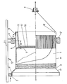
- the storage body 1 which is circular in cross section, has a conical frustoconical running surface 1 ⁇ on its rear cylindrical surface 1.
- the thread guide eyelet 2 moves in front of this.
- the thread F runs in the region of the frustoconical surface 1 ⁇ by relative rotation of the thread guide eyelet 2 to the storage body 1. It squeezes into the angular groove 3 and thereby pushes the previously wound thread layers close together in the direction of the head end 4 of the storage body.
- the individual fingers 5 extend above the head end 4 from the storage body 1. These are resilient. They lay under spring tension, directed in the direction of arrow x against ring 6.
- the ring 6 is crowned at its bottom 6 Unterseite.
- the thread F is withdrawn overhead from the storage body through the interior of the ring 6, preferably through a fixed eyelet 7.
- annular collar 8 This is formed by the one leg of the U-shaped cranked edge 9 of a pot 10. The latter is placed against the forehead surface 4 ⁇ of the head end 4 of the storage body 1 and fastened there in a suitable manner.
- the ring 6 sits on a carrier 11 in the axial direction x-x of the storage body 1 in a longitudinally displaceable manner.
- the effective free lever arm H of the fingers can be varied and thus also the contact force in the direction of the arrow x and thus also the braking of the thread when the trigger is pulled off.
- the thread is first stored in a winding movement, that is to say by a tangential feed, on the storage body 1 until a predetermined number of thread turns is present.
- the transmitter of a light barrier 12 scans, for example, the lateral surface 1 ⁇ . If the area of the preferably reflecting outer surface opposite to it is covered by thread layers, the further thread feed is blocked. If a pull-off now takes place, this area becomes free again and a corresponding switching device controls the new thread feed.
- the optimal thread take-off conditions can be set by displacing the ring 6, in this case even taking into account the properties of the thread material.
Landscapes
- Textile Engineering (AREA)
- Engineering & Computer Science (AREA)
- Forwarding And Storing Of Filamentary Material (AREA)
- Looms (AREA)
- Unwinding Of Filamentary Materials (AREA)
- Formation And Processing Of Food Products (AREA)
- Seeds, Soups, And Other Foods (AREA)
- Feeding, Discharge, Calcimining, Fusing, And Gas-Generation Devices (AREA)
- Spinning Or Twisting Of Yarns (AREA)
- Storage Of Web-Like Or Filamentary Materials (AREA)
- Electrical Discharge Machining, Electrochemical Machining, And Combined Machining (AREA)
- Yarns And Mechanical Finishing Of Yarns Or Ropes (AREA)
- Feeding And Watering For Cattle Raising And Animal Husbandry (AREA)
- Advancing Webs (AREA)
- Refuse Collection And Transfer (AREA)
- Knitting Machines (AREA)
- Extrusion Moulding Of Plastics Or The Like (AREA)
Abstract
Description
- Die Erfindung betrifft eine Fadenliefervorrichtung gemäß Gattungsbegriff des Hauptanspruches.
- Bei den bekannten Lösungen dieser Art (DE-AS 19 00 619) sitzen die elastischen Finger an dem Ring. Sie erstrecken sich geneigt zur Achse der Speichertrommel auf die Mantelfläche zu und liegen dort auf. Der Faden läuft durch den Ring und rutscht dabei unter den Fingern durch. Dies soll insbesondere die Fadenabzugsspannung vergleichmäßigen.
- Die Bauform ist nachteilig. Ring plus Finger bilden ein relativ empfindliches Kunststoffteil. Die sichere Lage auf der Mantelfläche der Trommel ist nicht immer zu gewährleisten. Zur Variation der von den Fingern ausgehenden vorgegebenen Abzugsspannungen müssen die Ringe ausgetauscht werden. Dies ist nicht möglich ohne Unterbrechungsstelle des Fadens, da dieser wieder durch den Ring gezogen werden muß.
- Aufgabe der Erfindung ist es, eine gattungsgemäße Vorrichtung so auszugestalten, daß bei vereinfachter und funktionssicherer Bauform Ring und Faden als voneinander getrennte Bauteile auftreten.
- Dies ist erreicht durch die im Hauptanspruch angegebenen Lösungsmerkmale. Die Unteransprüche stellen vorteilhafte Weiterbildungen dar.
- Zufolge dieser Ausgestaltung ist eine gattungsgemäße Fadenliefervorrichtung geschaffen, welche bei einfacher Bauform eine höhere Funkti onssicherheit und eine verbesserte Einsatzmöglichkeit schafft. Die elastischen Finger sind Elemente des Speicherkörpers und nicht mehr des Ringes. Der Ring ist unabhängig von den Fingern in der konzentrischen Lage zum Speicherkörper getragen. Sowohl der Ring als auch die Finger sind dadurch, daß sie vom abgezogenen Faden nicht aus ihrer Gebrauchsposition gebracht werden können, absolut funktionssicher. Es lassen sich auch höhere elastische Kräfte von den Fingern aufbringen, was eine höhere Abzugsspannung und damit auch eine relativ vergleichmäßigtere Abzugsspannung des Fadens bringt. Erstrecken sich die Finger in axialer Verlängerung der Speicherfläche, so kann die von ihnen gebildete Mantelfläche ggf. sogar kurzzeitig auch noch als Speicherfläche zur Verfügung stehen. Die Verschieblichkeit des Ringes in Achsrichtung des Speicherkörpers gestattet die Bestimmung der wirksamen Hebellänge der Finger und damit die Bestimmung und Variation der Andrückkraft der Finger gegen den Ring, was eine Variation der Fadenabzugsspannung ermöglicht. Um die Kraft, welche einer Ausweichbewegung der Federn entgegenwirkt, möglichst groß zu machen, andererseits aber die Anlagekraft zwischen Finger und Ring zu begrenzen, ist der Ringkragen vorgesehen. Die Bildung des Ringkragens vom U-förmig umgebogenen Rand eines Topfes begrenzt auch die Einwärtsfederungsmöglichkeit der Finger, was eine Beschädingungsgefahr, z. B. beim Transport oder dergleichen, bringt; dies schafft auch eine konstruktiv einfache Möglichkeit, evtl. durch unterschiedliche Topfelemente auch hier noch eine Variation vorzunehmen. Die Einstückigkeit der Finger am Speicherkörper ist insbesondere herstellungstechnisch und für die Stabilität von erheblichem Vorteil. Die Abzugsverhältnisse für den Faden sind ungeachtet der Stellung des Ringes dann optimiert, wenn der Ringkra gen außenseitig eine ballige Fadengleitfläche bildet. Ungeachtet, wo der Ring steht, bleibt die Fläche stets an gleicher Position.
- Der Gegenstand der Erfindung ist auf der beiliegenden Zeichnung in einem Ausführungsbeispiel dargestellt:
- Der im Querschnitt kreisförmig gestaltete Speicherkörper 1 besitzt rückwärtig anschließend an seine zylindrische Mantelfläche 1 eine kegelstumpfförmige Auflauffläche 1ʺ. Vor dieser bewegt sich die Fadenführungsöse 2. Durch Relativdrehbewegung der Fadenführungsöse 2 zum Speicherkörper 1 läuft der Faden F im Berich der kegelstumpfförmigen Fläche 1ʺ zu. Er zwängt sich in die Winkelkehle 3 ein und schiebt dadurch die jeweils vorher aufgewickelten Fadenlagen dicht an dicht liegend in Richtung des Kopfendes 4 des Speicherkörpers.
- Über das Kopfende 4 vorstehend erstrecken sich vom Speicherkörper 1 ausgehend die einzelnen Finger 5. Diese sind elastisch federnd ausgebildet. Sie legen sich unter federnder Vorspannung, gerichtet in Richtung des Pfeiles x gegen den Ring 6 an. Der Ring 6 ist an seiner Unterseite 6ʹ ballig gestaltet. Der Faden F wird durch das Innere des Ringes 6 über Kopf vom Speicherkörper abgezogen, vorzugsweise durch eine Festöse 7.
- Die Auswärtsfederung der Finger 5 ist begrenzt durch einen Ringkragen 8. Dieser wird von dem einen Schenkel des U-förmig abgekröpften Randes 9 eines Topfes 10 gebildet. Letzterer ist gesetzt gegen die Stirn fläche 4ʹ des Kopfendes 4 des Speicherkörpers 1 und dort in geeigneter Weise befestigt.
- Der Ring 6 sitzt auf einem Träger 11 in Achsrichtung x-x des Speicherkörpers 1 längsverschieblich. Durch diese Längsverschiebungs-Einstellung kann der wirksame freie Hebelarm H der Finger variiert werden und damit auch die Anlagekraft in Richtung des Pfeiles x und somit darüber auch die Bremsung des Fadens beim Abzug.
- Bei diesem Abzug gleitet der Faden über die Fadengleitfläche 8ʹ des Ringkragens 8. Diese ist möglichst glatt und in Abzugsrichtung gerundet gestaltet.
- Bei der Arbeitsweise der Vorrichtung wird der Faden zunächst in Wikkelbewegung, also durch tangentialen Zulauf auf dem Speicherkörper 1 gespeichert, bis eine vorgesehene Anzahl von Fadenwindungen vorliegt. Der Sender einer Lichtschranke 12 tastet dabei beispielsweise die Mantelfläche 1ʹ ab. Wird der ihm gegenüberliegende Bereich der vorzugsweise spiegelnden Mantelfläche von Fadenlagen überdeckt, so wird die weitere Fadenzufuhr gesperrt. Erfolgt nun ein Abziehen, so wird diese Fläche wieder frei und eine entsprechende Schalteinrichtung steuert den erneuten Fadenzulauf. Während des Betriebs kann man durch Verschieben des Ringes 6 die optimalen Fadenabzugsbedingungen einstellen, dabei also sogar die Eigenschaften des Fadenmaterials berücksichtigen.
- Alle in der Beschreibung erwähnten und in der Zeichnung dargestellten neuen Merkmale sind erfindungswesentlich, auch soweit sie in den Ansprüchen nicht ausdrücklich beansprucht sind.
Claims (8)
Priority Applications (20)
| Application Number | Priority Date | Filing Date | Title |
|---|---|---|---|
| EP87105387A EP0286694B1 (de) | 1987-04-11 | 1987-04-11 | Fadenliefervorrichtung |
| AT87105387T ATE45331T1 (de) | 1987-04-11 | 1987-04-11 | Fadenliefervorrichtung. |
| ES87105387T ES2009817B3 (es) | 1987-04-11 | 1987-04-11 | Dispositivo suministrador de hil |
| DE8787105387T DE3760411D1 (en) | 1987-04-11 | 1987-04-11 | Thread delivery device |
| US07/145,346 US4828192A (en) | 1987-04-11 | 1988-01-19 | Thread feeder |
| IN153/MAS/88A IN171141B (de) | 1987-04-11 | 1988-03-09 | |
| EP88104231A EP0286860B1 (de) | 1987-04-11 | 1988-03-17 | Fadenliefervorrichtung |
| AT88104231T ATE57161T1 (de) | 1987-04-11 | 1988-03-17 | Fadenliefervorrichtung. |
| DE8888104231T DE3860723D1 (de) | 1987-04-11 | 1988-03-17 | Fadenliefervorrichtung. |
| ES88104231T ES2018059B3 (es) | 1987-04-11 | 1988-03-17 | Dispositivo de suministro de hilo |
| KR1019880003940A KR940000055B1 (ko) | 1987-04-11 | 1988-04-07 | 실 공급장치 |
| SU884355500A SU1570652A3 (ru) | 1987-04-11 | 1988-04-07 | Нитенакопитель |
| CA000563604A CA1302068C (en) | 1987-04-11 | 1988-04-08 | Thread feeder |
| BR8801693A BR8801693A (pt) | 1987-04-11 | 1988-04-08 | Dispositivo fornecedor de fio |
| CN88102126A CN1011876B (zh) | 1987-04-11 | 1988-04-09 | 喂纱装置 |
| JP63088893A JPS63262376A (ja) | 1987-04-11 | 1988-04-11 | 給糸装置 |
| PT87212A PT87212B (pt) | 1987-04-11 | 1988-04-11 | Dispositivo alimentador de fio |
| CS882469A CZ246988A3 (en) | 1987-04-11 | 1988-04-11 | Thread feeding device |
| GR89400130T GR3000124T3 (en) | 1987-04-11 | 1989-08-10 | Thread delivery device |
| GR90400765T GR3000932T3 (en) | 1987-04-11 | 1990-10-12 | Thread delivery device |
Applications Claiming Priority (1)
| Application Number | Priority Date | Filing Date | Title |
|---|---|---|---|
| EP87105387A EP0286694B1 (de) | 1987-04-11 | 1987-04-11 | Fadenliefervorrichtung |
Publications (2)
| Publication Number | Publication Date |
|---|---|
| EP0286694A1 true EP0286694A1 (de) | 1988-10-19 |
| EP0286694B1 EP0286694B1 (de) | 1989-08-09 |
Family
ID=8196912
Family Applications (2)
| Application Number | Title | Priority Date | Filing Date |
|---|---|---|---|
| EP87105387A Expired EP0286694B1 (de) | 1987-04-11 | 1987-04-11 | Fadenliefervorrichtung |
| EP88104231A Expired - Lifetime EP0286860B1 (de) | 1987-04-11 | 1988-03-17 | Fadenliefervorrichtung |
Family Applications After (1)
| Application Number | Title | Priority Date | Filing Date |
|---|---|---|---|
| EP88104231A Expired - Lifetime EP0286860B1 (de) | 1987-04-11 | 1988-03-17 | Fadenliefervorrichtung |
Country Status (15)
| Country | Link |
|---|---|
| US (1) | US4828192A (de) |
| EP (2) | EP0286694B1 (de) |
| JP (1) | JPS63262376A (de) |
| KR (1) | KR940000055B1 (de) |
| CN (1) | CN1011876B (de) |
| AT (2) | ATE45331T1 (de) |
| BR (1) | BR8801693A (de) |
| CA (1) | CA1302068C (de) |
| CZ (1) | CZ246988A3 (de) |
| DE (2) | DE3760411D1 (de) |
| ES (2) | ES2009817B3 (de) |
| GR (2) | GR3000124T3 (de) |
| IN (1) | IN171141B (de) |
| PT (1) | PT87212B (de) |
| SU (1) | SU1570652A3 (de) |
Families Citing this family (11)
| Publication number | Priority date | Publication date | Assignee | Title |
|---|---|---|---|---|
| IT1258241B (it) * | 1992-11-05 | 1996-02-22 | Alimentatore di trama | |
| IT1263623B (it) * | 1993-02-23 | 1996-08-27 | Roj Electrotex Nuova Srl | Alimentatore di filo |
| US7988765B2 (en) | 2008-02-20 | 2011-08-02 | Gtlpetrol Llc | Systems and processes for processing hydrogen and carbon monoxide |
| IT1402405B1 (it) | 2010-10-22 | 2013-09-04 | Btsr Int Spa | Dispositivo di alimentazione-separazione filo. |
| JP5804306B2 (ja) | 2011-02-07 | 2015-11-04 | 村田機械株式会社 | 糸貯留装置及び糸巻取機 |
| JP2016055985A (ja) * | 2014-09-10 | 2016-04-21 | 村田機械株式会社 | 糸巻取装置 |
| ITUB20152769A1 (it) * | 2015-08-03 | 2017-02-03 | Btsr Int Spa | Alimentatore di filo ad accumulo con organo frenante e elementi intercambiabili |
| JP2017077949A (ja) * | 2015-10-21 | 2017-04-27 | 村田機械株式会社 | 糸巻取装置 |
| CN106012283B (zh) * | 2016-08-02 | 2017-10-10 | 徐州恒辉编织机械有限公司 | 一种编织机的大行程无摩擦锭子 |
| CN106868655B (zh) * | 2017-04-13 | 2023-09-26 | 江西省山星纺机实业有限公司 | 一种环锭纺细纱机叶子板式的假捻装置 |
| CN111362067B (zh) * | 2020-03-24 | 2021-06-22 | 海宁市万路针织有限公司 | 针织品纱线卷绕装置 |
Citations (1)
| Publication number | Priority date | Publication date | Assignee | Title |
|---|---|---|---|---|
| EP0177797A1 (de) * | 1984-10-11 | 1986-04-16 | Gustav Memminger | Fadenspeicher und -liefervorrichtung, insbesondere für Textilmaschinen |
Family Cites Families (5)
| Publication number | Priority date | Publication date | Assignee | Title |
|---|---|---|---|---|
| CH394899A (it) * | 1961-10-31 | 1965-06-30 | Sobrevin Soc De Brevets Ind Et | Apparecchio per la regolazione della tensione all'uscita di un filo nel passaggio dal suo svolgimento al suo avvolgimento |
| ES374971A1 (es) * | 1969-01-07 | 1972-01-16 | Joel Rosen | Almacenador suministrador para hilos. |
| CH550730A (de) * | 1972-04-28 | 1974-06-28 | Sulzer Ag | Verfahren fuer den gebremsten abzug fadenfoermigen materials von einem wickelkoerper einer speichereinrichtung fuer textilmaschinen und einrichtung zur durchfuehrung des verfahrens. |
| IT1087411B (it) * | 1977-09-29 | 1985-06-04 | Savio & C Spa | Dispositivo per il controllo della tensione di filo svolgentesi da un corpo di supporto di filo |
| DE3212186C2 (de) * | 1982-04-01 | 1984-07-19 | Čeboksarskij maŠinostroitel'nyj zavod, Čeboksary | Einrichtung zur Speicherung eines Fadens bei seiner Zuführung zum Webfach einer Webmaschine |
-
1987
- 1987-04-11 ES ES87105387T patent/ES2009817B3/es not_active Expired
- 1987-04-11 AT AT87105387T patent/ATE45331T1/de not_active IP Right Cessation
- 1987-04-11 EP EP87105387A patent/EP0286694B1/de not_active Expired
- 1987-04-11 DE DE8787105387T patent/DE3760411D1/de not_active Expired
-
1988
- 1988-01-19 US US07/145,346 patent/US4828192A/en not_active Expired - Fee Related
- 1988-03-09 IN IN153/MAS/88A patent/IN171141B/en unknown
- 1988-03-17 DE DE8888104231T patent/DE3860723D1/de not_active Expired - Fee Related
- 1988-03-17 ES ES88104231T patent/ES2018059B3/es not_active Expired - Lifetime
- 1988-03-17 EP EP88104231A patent/EP0286860B1/de not_active Expired - Lifetime
- 1988-03-17 AT AT88104231T patent/ATE57161T1/de not_active IP Right Cessation
- 1988-04-07 SU SU884355500A patent/SU1570652A3/ru active
- 1988-04-07 KR KR1019880003940A patent/KR940000055B1/ko not_active IP Right Cessation
- 1988-04-08 CA CA000563604A patent/CA1302068C/en not_active Expired - Fee Related
- 1988-04-08 BR BR8801693A patent/BR8801693A/pt not_active Application Discontinuation
- 1988-04-09 CN CN88102126A patent/CN1011876B/zh not_active Expired
- 1988-04-11 CZ CS882469A patent/CZ246988A3/cs unknown
- 1988-04-11 JP JP63088893A patent/JPS63262376A/ja active Pending
- 1988-04-11 PT PT87212A patent/PT87212B/pt not_active IP Right Cessation
-
1989
- 1989-08-10 GR GR89400130T patent/GR3000124T3/el unknown
-
1990
- 1990-10-12 GR GR90400765T patent/GR3000932T3/el unknown
Patent Citations (1)
| Publication number | Priority date | Publication date | Assignee | Title |
|---|---|---|---|---|
| EP0177797A1 (de) * | 1984-10-11 | 1986-04-16 | Gustav Memminger | Fadenspeicher und -liefervorrichtung, insbesondere für Textilmaschinen |
Also Published As
| Publication number | Publication date |
|---|---|
| PT87212A (pt) | 1989-05-12 |
| EP0286694B1 (de) | 1989-08-09 |
| US4828192A (en) | 1989-05-09 |
| JPS63262376A (ja) | 1988-10-28 |
| EP0286860A1 (de) | 1988-10-19 |
| KR880012468A (ko) | 1988-11-26 |
| GR3000932T3 (en) | 1991-12-10 |
| EP0286860B1 (de) | 1990-10-03 |
| KR940000055B1 (ko) | 1994-01-05 |
| DE3760411D1 (en) | 1989-09-14 |
| SU1570652A3 (ru) | 1990-06-07 |
| DE3860723D1 (de) | 1990-11-08 |
| GR3000124T3 (en) | 1990-11-29 |
| CN88102126A (zh) | 1988-10-26 |
| CZ246988A3 (en) | 1994-03-16 |
| CN1011876B (zh) | 1991-03-06 |
| IN171141B (de) | 1992-08-01 |
| ATE45331T1 (de) | 1989-08-15 |
| PT87212B (pt) | 1993-11-30 |
| ATE57161T1 (de) | 1990-10-15 |
| ES2009817B3 (es) | 1989-10-16 |
| ES2018059B3 (es) | 1991-03-16 |
| BR8801693A (pt) | 1988-11-16 |
| CA1302068C (en) | 1992-06-02 |
Similar Documents
| Publication | Publication Date | Title |
|---|---|---|
| DE2548770C3 (de) | Fadenspeicher- und Liefervorrichtung | |
| DE708732C (de) | Spulvorrichtung fuer kuenstliche endlose Faeden u. dgl. insbesondere solche aus Glas | |
| EP0286694A1 (de) | Fadenliefervorrichtung | |
| DE2841926A1 (de) | Vorrichtung zur steuerung der abzugsspannung des von einem tragkoerper ablaufenden garns oder fadens | |
| EP0170798B1 (de) | Fadenspeicher- und Liefervorrichtung | |
| EP0201794A2 (de) | Aus zwei Hülsenteilen bestehender Wickelträger | |
| DE2406597B2 (de) | Fadenbremse für den ablaufenden Faden einer Fadenspeicher- und Faden-Liefervorrichtung | |
| DE3124482C2 (de) | Bremsvorrichtung an einer Doppeldraht-Zwirnspindel | |
| DE3130615C2 (de) | Fadenführungsvorrichtung | |
| DE2343776A1 (de) | Vorrichtung zum uebertragen von garndrehungen bei ringspinnmaschinen | |
| EP0448949B1 (de) | Spindel zum Herstellen eines Fadens | |
| DE2736344A1 (de) | Vorrichtung zum steuern des abwickelns von draht u.dgl. von einer spule | |
| DE19904793C1 (de) | Vorrichtung zum Klemmen von Unterwindefäden an einer Spinnspindel | |
| DE2456440B2 (de) | Fadenspeichervorrichtung | |
| DE3310438A1 (de) | In ihrer geometrischen form veraenderbare ablaufhilfe fuer den ueberkopf-abzug eines fadens von einer vorlagespule | |
| DE2348908C2 (de) | Spinn- oder Zwirnspindel mit einem durch einen Wirtel antreibbaren Spindelschaft | |
| DE3044315A1 (de) | Huelsenspannvorrichtung fuer mehrfach-spulentraeger | |
| DE2755915B1 (de) | Garnhuelse aus Kunststoff | |
| DE7330642U (de) | Halterung für Hülsen oder Spulen auf Spinn- und Zwirnspindeln | |
| DE253206C (de) | ||
| DE4103110A1 (de) | Garnspulenhalter | |
| DE1131568B (de) | Spindel mit abgeflachter Spindelspitze fuer ballonloses Spinnen und Zwirnen | |
| DE1710155C3 (de) | Fadenbremse für von Garnspulen in Spulengattern ablaufende Fäden | |
| DE2355065B2 (de) | Laeuferbremse fuer ringzwirn- oder ringspinnmaschinen | |
| CH521282A (de) | Spulenhülse |
Legal Events
| Date | Code | Title | Description |
|---|---|---|---|
| PUAI | Public reference made under article 153(3) epc to a published international application that has entered the european phase |
Free format text: ORIGINAL CODE: 0009012 |
|
| 17P | Request for examination filed |
Effective date: 19880310 |
|
| AK | Designated contracting states |
Kind code of ref document: A1 Designated state(s): AT BE CH DE ES FR GB GR IT LI LU NL SE |
|
| 17Q | First examination report despatched |
Effective date: 19890123 |
|
| ITF | It: translation for a ep patent filed | ||
| GRAA | (expected) grant |
Free format text: ORIGINAL CODE: 0009210 |
|
| AK | Designated contracting states |
Kind code of ref document: B1 Designated state(s): AT BE CH DE ES FR GB GR IT LI LU NL SE |
|
| REF | Corresponds to: |
Ref document number: 45331 Country of ref document: AT Date of ref document: 19890815 Kind code of ref document: T |
|
| ET | Fr: translation filed | ||
| REF | Corresponds to: |
Ref document number: 3760411 Country of ref document: DE Date of ref document: 19890914 |
|
| GBT | Gb: translation of ep patent filed (gb section 77(6)(a)/1977) | ||
| REG | Reference to a national code |
Ref country code: GR Ref legal event code: FG4A Free format text: 3000124 |
|
| PLBE | No opposition filed within time limit |
Free format text: ORIGINAL CODE: 0009261 |
|
| STAA | Information on the status of an ep patent application or granted ep patent |
Free format text: STATUS: NO OPPOSITION FILED WITHIN TIME LIMIT |
|
| 26N | No opposition filed | ||
| PGFP | Annual fee paid to national office [announced via postgrant information from national office to epo] |
Ref country code: SE Payment date: 19920319 Year of fee payment: 6 |
|
| PGFP | Annual fee paid to national office [announced via postgrant information from national office to epo] |
Ref country code: FR Payment date: 19920320 Year of fee payment: 6 |
|
| PGFP | Annual fee paid to national office [announced via postgrant information from national office to epo] |
Ref country code: BE Payment date: 19920324 Year of fee payment: 6 |
|
| PGFP | Annual fee paid to national office [announced via postgrant information from national office to epo] |
Ref country code: GR Payment date: 19920326 Year of fee payment: 6 |
|
| PGFP | Annual fee paid to national office [announced via postgrant information from national office to epo] |
Ref country code: LU Payment date: 19920330 Year of fee payment: 6 Ref country code: AT Payment date: 19920330 Year of fee payment: 6 |
|
| PGFP | Annual fee paid to national office [announced via postgrant information from national office to epo] |
Ref country code: GB Payment date: 19920402 Year of fee payment: 6 Ref country code: DE Payment date: 19920402 Year of fee payment: 6 |
|
| PGFP | Annual fee paid to national office [announced via postgrant information from national office to epo] |
Ref country code: ES Payment date: 19920413 Year of fee payment: 6 |
|
| ITTA | It: last paid annual fee | ||
| PGFP | Annual fee paid to national office [announced via postgrant information from national office to epo] |
Ref country code: NL Payment date: 19920430 Year of fee payment: 6 |
|
| PGFP | Annual fee paid to national office [announced via postgrant information from national office to epo] |
Ref country code: CH Payment date: 19920722 Year of fee payment: 6 |
|
| EPTA | Lu: last paid annual fee | ||
| PG25 | Lapsed in a contracting state [announced via postgrant information from national office to epo] |
Ref country code: LU Free format text: LAPSE BECAUSE OF NON-PAYMENT OF DUE FEES Effective date: 19930411 Ref country code: GB Effective date: 19930411 Ref country code: AT Effective date: 19930411 |
|
| PG25 | Lapsed in a contracting state [announced via postgrant information from national office to epo] |
Ref country code: SE Effective date: 19930412 Ref country code: ES Free format text: LAPSE BECAUSE OF NON-PAYMENT OF DUE FEES Effective date: 19930412 |
|
| PG25 | Lapsed in a contracting state [announced via postgrant information from national office to epo] |
Ref country code: LI Effective date: 19930430 Ref country code: CH Effective date: 19930430 Ref country code: BE Effective date: 19930430 |
|
| BERE | Be: lapsed |
Owner name: SOC DE BREVETS INDUSTRIELS-ETABLISSEMENT SOBREVIN Effective date: 19930430 |
|
| PG25 | Lapsed in a contracting state [announced via postgrant information from national office to epo] |
Ref country code: GR Free format text: THE PATENT HAS BEEN ANNULLED BY A DECISION OF A NATIONAL AUTHORITY Effective date: 19931031 |
|
| PG25 | Lapsed in a contracting state [announced via postgrant information from national office to epo] |
Ref country code: NL Effective date: 19931101 |
|
| GBPC | Gb: european patent ceased through non-payment of renewal fee |
Effective date: 19930411 |
|
| NLV4 | Nl: lapsed or anulled due to non-payment of the annual fee | ||
| PG25 | Lapsed in a contracting state [announced via postgrant information from national office to epo] |
Ref country code: FR Effective date: 19931229 |
|
| REG | Reference to a national code |
Ref country code: CH Ref legal event code: PL |
|
| PG25 | Lapsed in a contracting state [announced via postgrant information from national office to epo] |
Ref country code: DE Effective date: 19940101 |
|
| REG | Reference to a national code |
Ref country code: FR Ref legal event code: ST |
|
| REG | Reference to a national code |
Ref country code: GR Ref legal event code: MM2A Free format text: 3000124 |
|
| EUG | Se: european patent has lapsed |
Ref document number: 87105387.2 Effective date: 19931110 |
|
| REG | Reference to a national code |
Ref country code: GB Ref legal event code: 746 Effective date: 19970205 |
|
| REG | Reference to a national code |
Ref country code: ES Ref legal event code: FD2A Effective date: 19990301 |
|
| PG25 | Lapsed in a contracting state [announced via postgrant information from national office to epo] |
Ref country code: IT Free format text: LAPSE BECAUSE OF NON-PAYMENT OF DUE FEES;WARNING: LAPSES OF ITALIAN PATENTS WITH EFFECTIVE DATE BEFORE 2007 MAY HAVE OCCURRED AT ANY TIME BEFORE 2007. THE CORRECT EFFECTIVE DATE MAY BE DIFFERENT FROM THE ONE RECORDED. Effective date: 20050411 |